| 2 4 0 T U R B O . C O M D A V E ' S V O L V O P A G E
| ||||||||||||||||||||||||||||||||||||||||||||||||||
| 2 4 0 T U R B O . C O M D A V E ' S V O L V O P A G E
| ||||||||||||||||||||||||||||||||||||||||||||||||||
| Go to 240 Headlight Page | Go to Headlight RELAY Page |
|
| Navigate this Page |
||
| 240 TAILLIGHT DIAGRAMS |
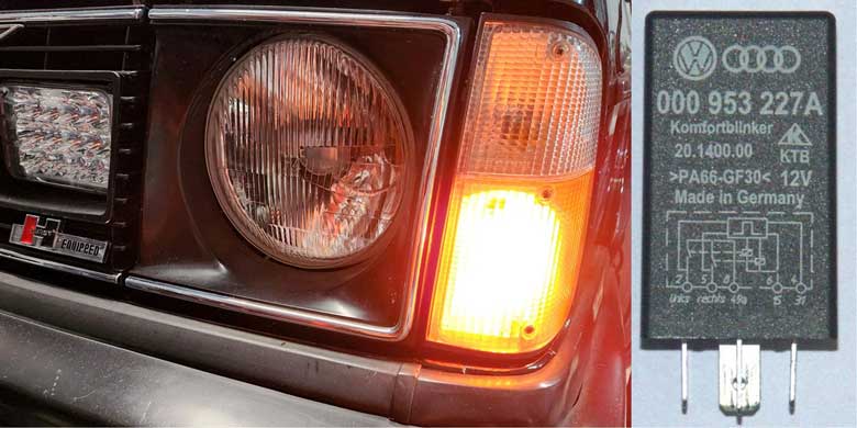
240 "Komfort" Blinker Mod |
|
| Dealing with the Bulb Failure Sensor (Part 1) |
||
| By-Passing the Bulb Failure Sensor (Part 2) | ||
| By-Passing a Bulb Failure Sensor (Part 3) | ||
| 240 REAR BULBS |
Painting 240 Taillights |
|
| HARDWIRING Your 240 Taillights |
||
| Quick Fix using FOIL |
||
|
||
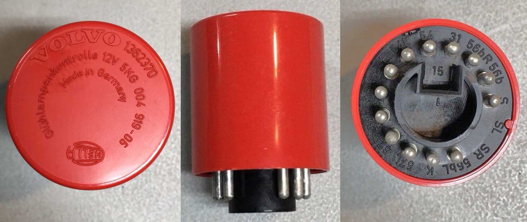
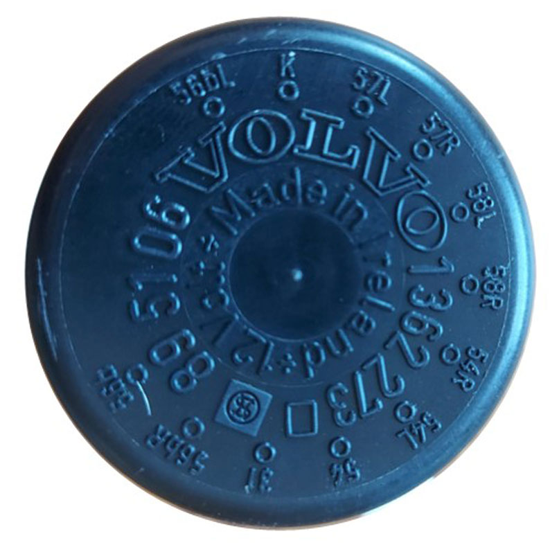
This switch is a metal case design with a 5-pole plastic plug. In most cases this plug only uses 3 poles, so only 3 wires will exist. In some non-USA countries this switch will use 5 poles. More on this is found in my 240 HEADLIGHT PAGE: https://www.240turbo.com/headlight.html. 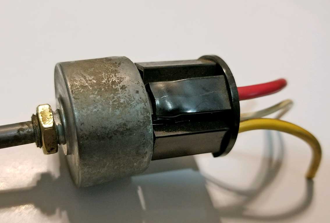 
|
  |
 |
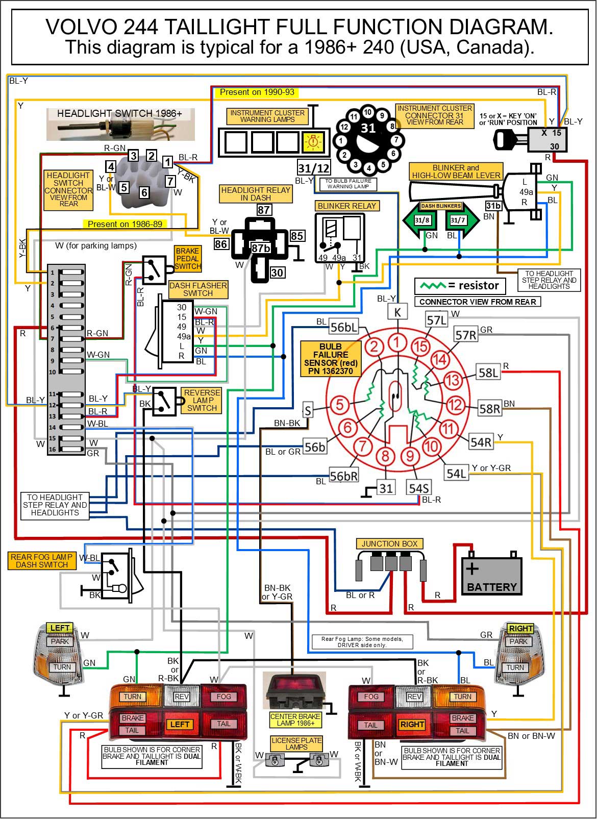
More info and DIAGRAMS concerning the HEADLIGHT circuits can be found in my Headlight Relay Page.
|
|||||||||||||||||||||||
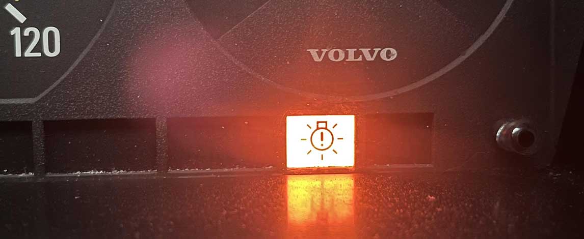
FAILURE SYMPTOMS: The symptoms of failure can be headlights or tail lights (or sometimes just one whole side) that will not work even after verifying the fuses, switches, headlight relays and wiring are all in good order. This DIY bypass plug below was featured in the following discussion forum: turbobricks.com/index.php/deleting-bulb-failure-circuits.240085/ 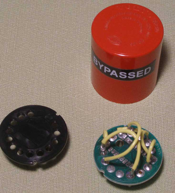 |
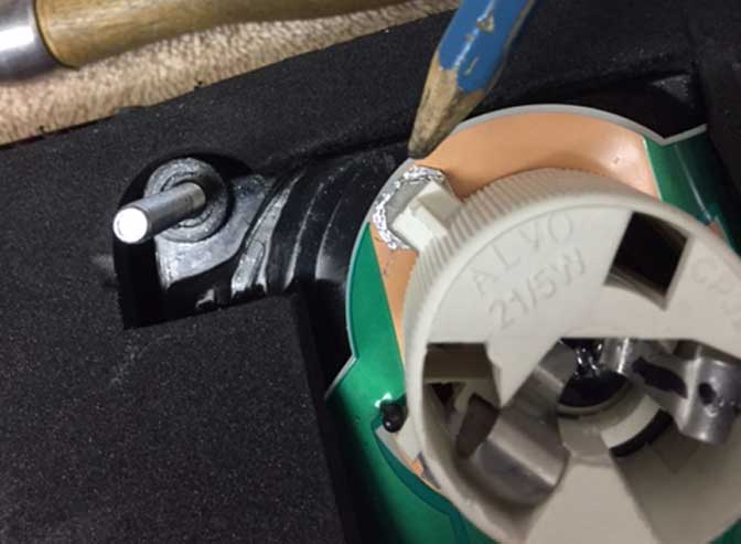
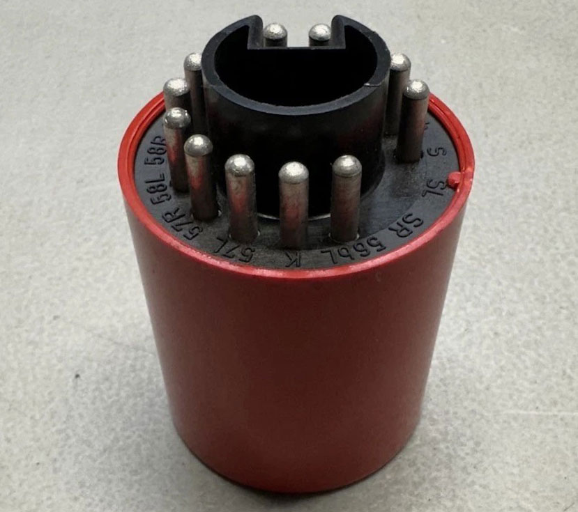
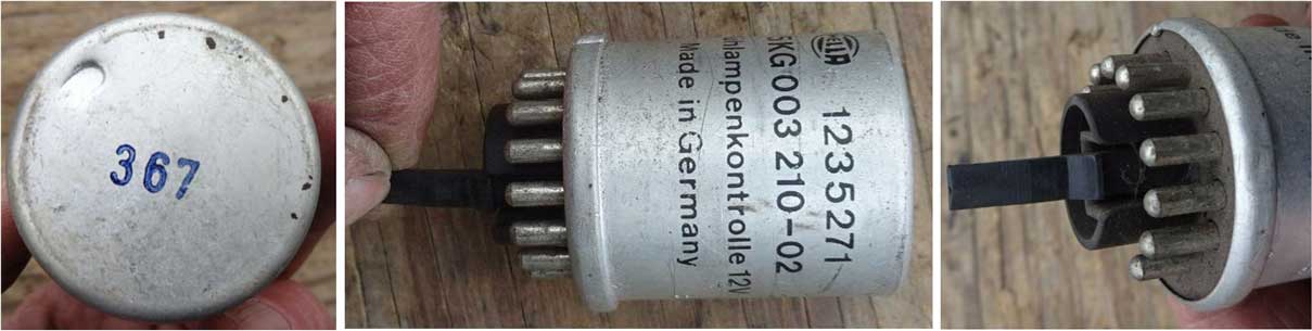
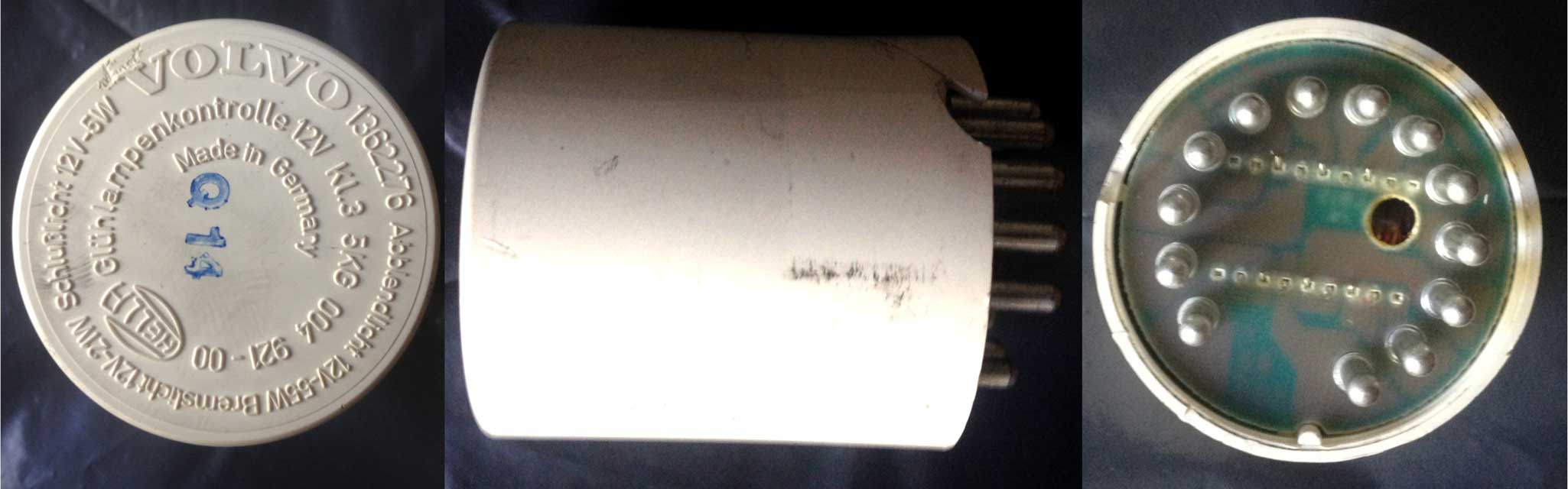
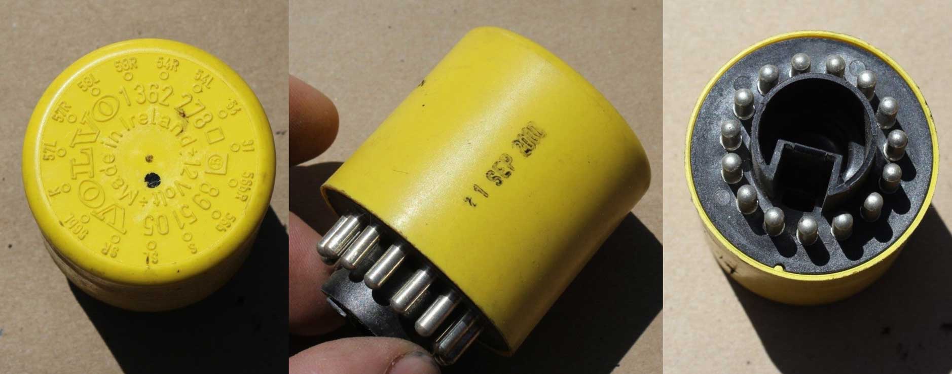
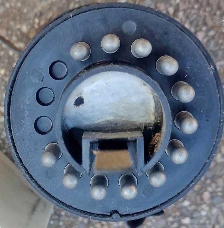
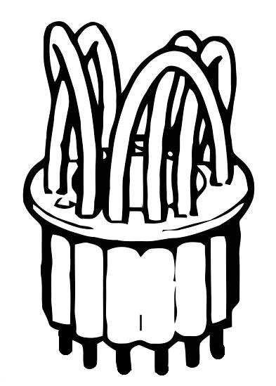
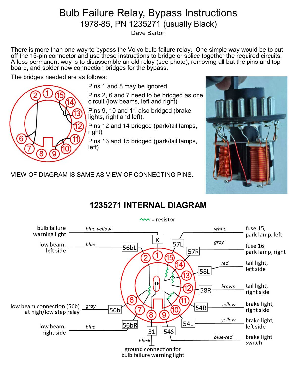
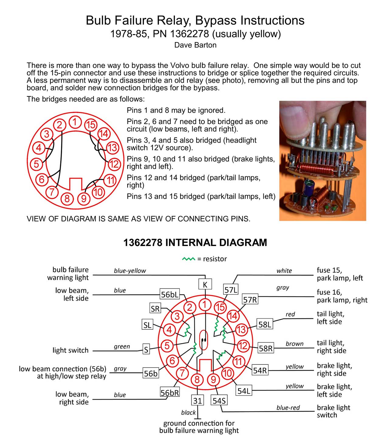
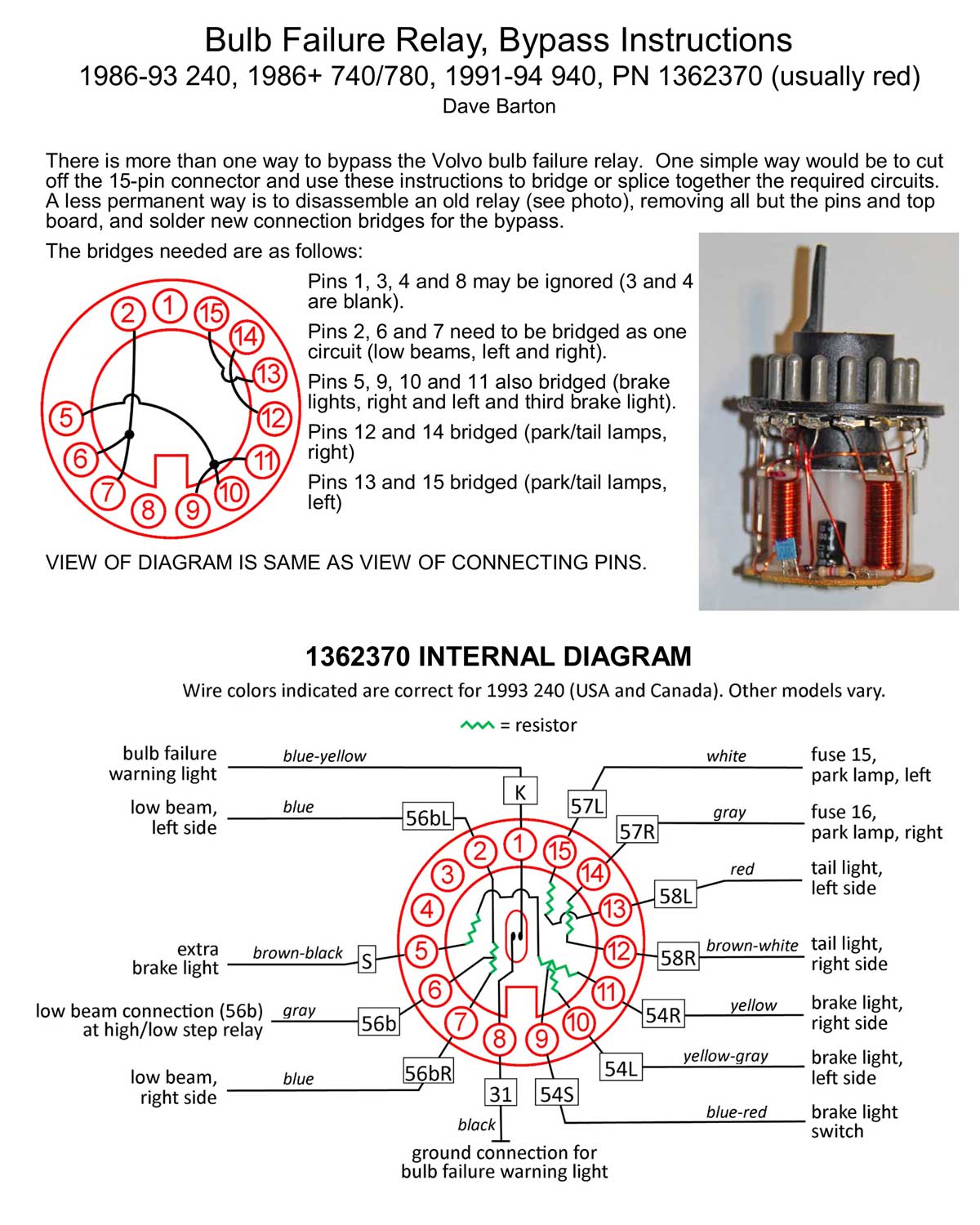
If you don't feel like going to the trouble of modifying a Bulb Failure Sensor internally, there is a MUCH SIMPLER way to bypass these circuits without using a sensor. And I don't mean to suggest cutting off the 15-pin plug and splicing wires together (which of course you can do if you like). A better method, with no barbaric butchery, is to assemble some simple crimp terminals with a few short pieces of wire. Then unplug your sensor and insert the new leads into the female 15-pin connector, respective of the bypass diagrams shown below As it turns out, this connector uses fairly common 3.5 mm bullet terminals. So all you need are some male bullet terminals and some wire and some heat-shrink tubing for insulation. Coincidentally, these 3.5 mm male terminals are available cheap on-line or also in my Harness Parts Page HERE. Diagram view is facing the rear of the key switch PLUG. 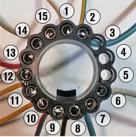 In the photos below, you can see how these bypass bullet terminals and wires will look. The configuration is different for different sensors, so pay attention to the diagrams. If your car uses a sensor not shown above, it will be a simple thing to open it up to see what pins are bridged. 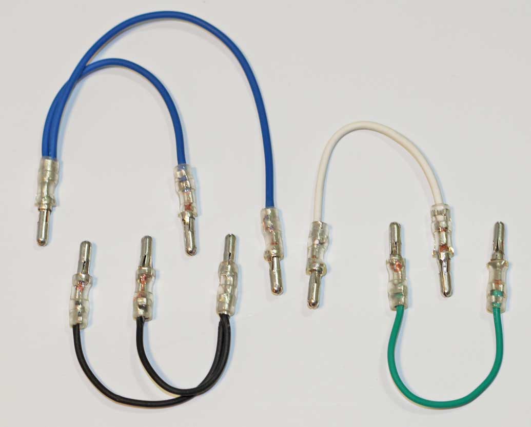 Diagram view is facing the rear of the key switch PLUG. 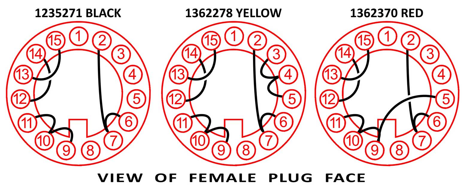 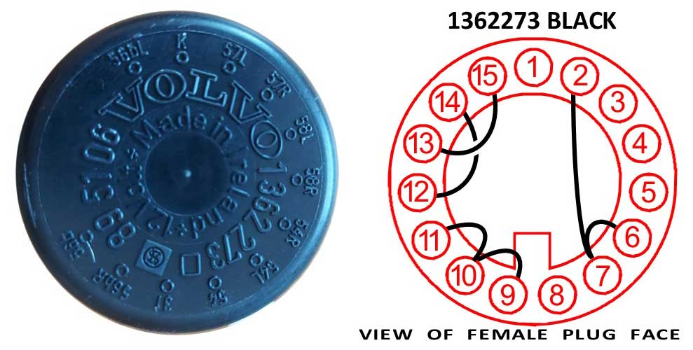 Tamara from Albuquerque sent the below photos of her bypass project: "I just accomplished the bypass on the failed bulb relay on my 240. Worked like a charm! Thank you so much for all of your pains-taking work in putting together all of the detailed and supremely helpful information on your website. It is so appreciated. I found it easier to deal with by removing the instrument cluster. That way I could get both hands on the relay and sit upright to put the bypass pieces in. I also had to lever the relay and connector apart with a screwdriver. I had fought with it for awhile to no avail then I realized some leverage was called for. It made a little click and came apart easily. That's when I discovered it had a barb holding it together. It's great to have brake lights again!" 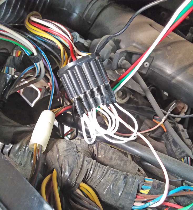
 |
The below image came from Matthews Volvo Site Volvo Bulb Guide.
I'm adding this here because I get have received a fair number of emails from 240 owners who have melting taillights or bulb holders or general questions about rear bulbs. If you have melting taillight lenses or bulb holders, then I'm suggesting you probably have the wrong bulbs installed in your car. For example, many 240 taillights (not brake lights) require a small 5 or 10 watt bulb, typically an Osram 5007 or 5008 or Sylvania 5007 or 5008. This is the proper bulb for the rear running lights (this is the bulb shown below, top row, far right, BA15s or 5007 (5 watts), or 5008 (10 watts). The TROUBLE begins when a 240 owners goes to the local auto parts store and buys what fits, often getting a common 1156 bulb, because it has the same base and it fits the same. The problem is that a standard 1156 bulb will typically be rated at about 26 watts. That's too much current and it adds a LOT of extra heat. That will be the reason why your taillights or your bulb holders are melting. 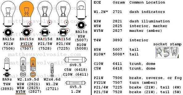 This first image below is a common 1156 bulb, which some people incorrectly use as a substitute for an Osram 5007 or 5008 or Sylvania 5007 or 5008. The Sylvania 5007 (5 watts) or 5008 (10 watts) at the below-right should be used instead. THIS bulb below-right is the correct bulb to use for a 240 taillight (but not for brake lights). 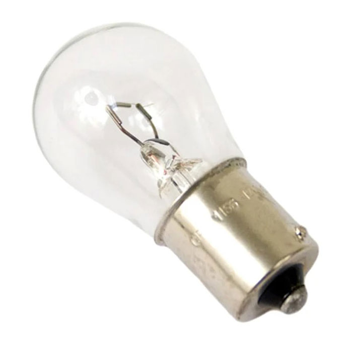 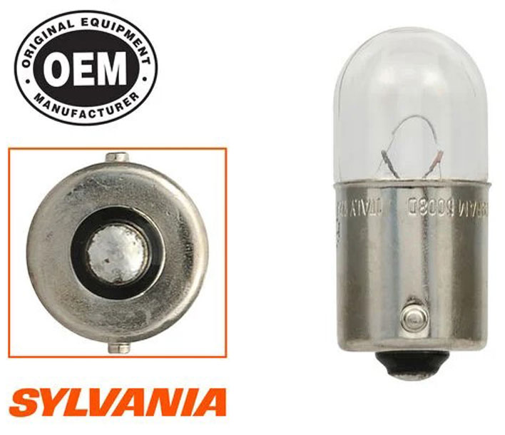 The below image is typical '85-93 240 taillight configuration with proper bulb part numbers. 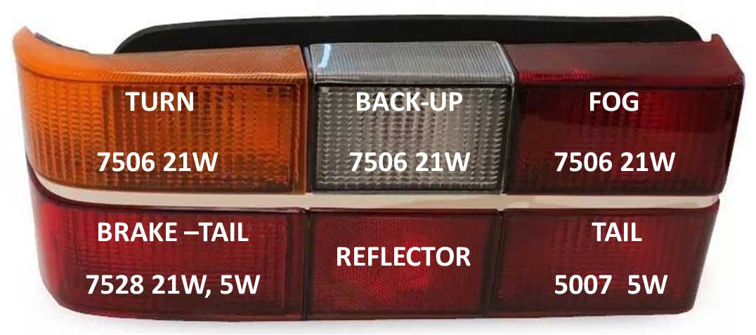 |
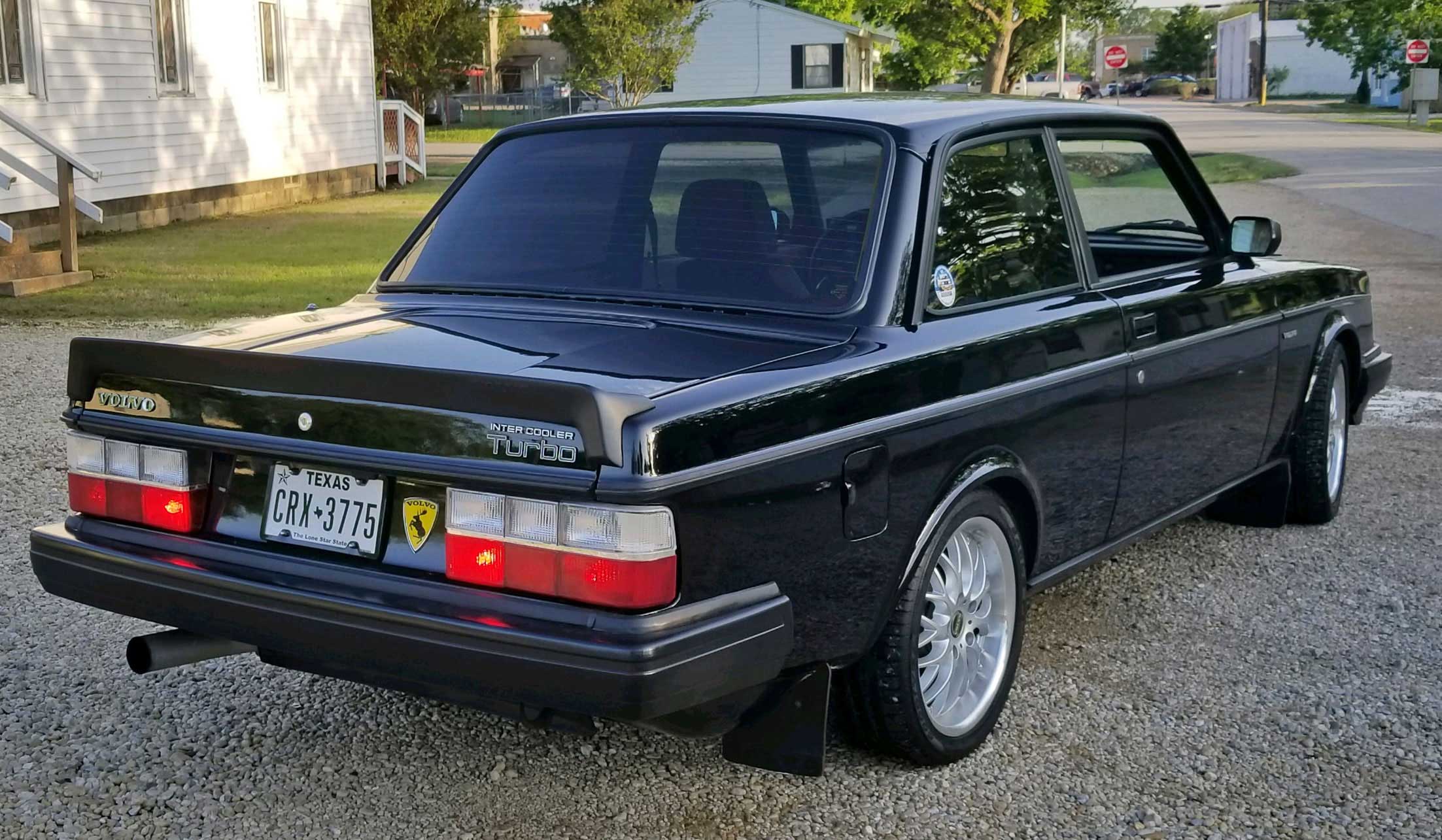
I did this hard-wiring modification to my 242 more than 15 years ago and I have never had a rear bulb problem since.  Volvo first began using these 6-panel taillights with PRINTED CIRCUIT BOARDS in 1979 for upscale 6-cylinder models. Lesser trim level sedans received the smaller 5-panel lights back then. After 1979 the 6-panel lights were used in more upscale 4-cylinder models, such as the GL, GLT and Turbo. Then in 1984 all 240 sedan models began receiving these 6-panel taillights. This rear bulb info below is from the 1984 240 Owner's Manual. 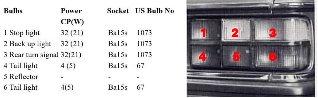 In 1985 the 240 sedan models received revised 6-panel lights, which included a DUAL FILAMENT brake/tail light bulb. The brake/tail light was moved to the lower outside corner. And a new rear fog lamp was added for some models. These tail lights remained in use until 1993. 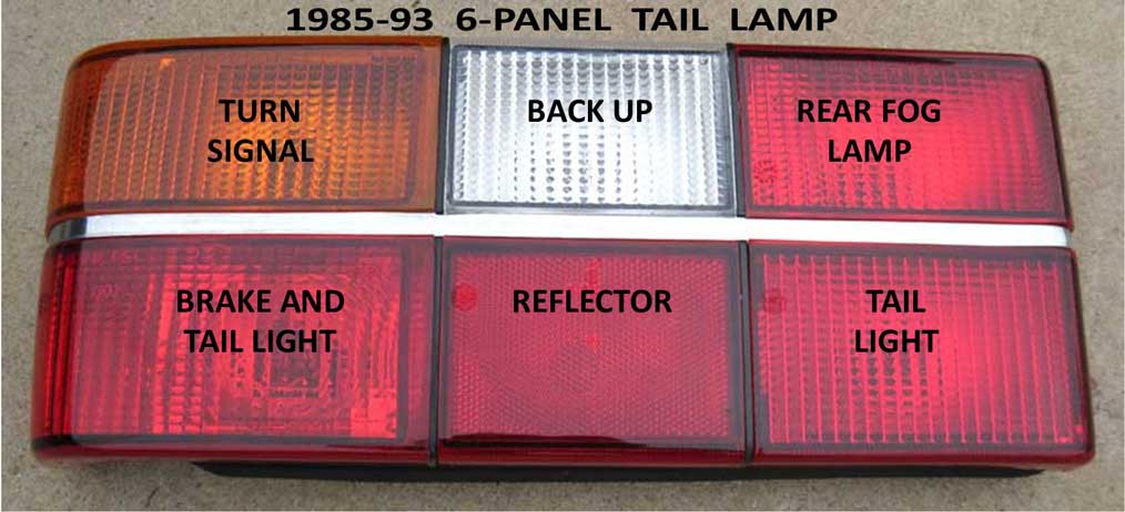 This rear bulb info below is from a 1989 240 Owner's Manual. 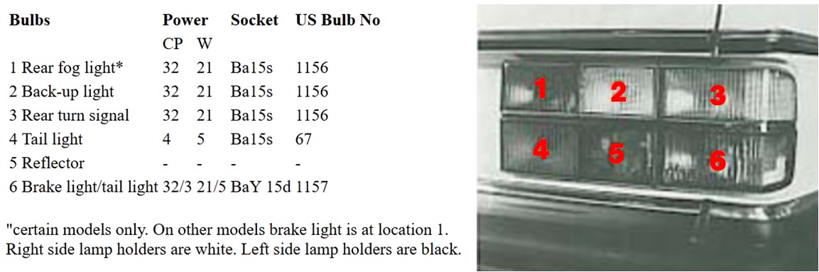 Most people with these tail lamps know what it's like to have bulbs that stop working due to connection issues between the plastic bulb holder and the printed circuit board conductor (PCB). It can be frustrating. Hard-wiring them sounds like a big deal, but it's not hard at all. It means you will be tossing out your old circuit boards and then attaching wires directly to the contacts on your bulb holders. The wires can be soldered or crimp connectors can be used. I prefer crimp connectors.
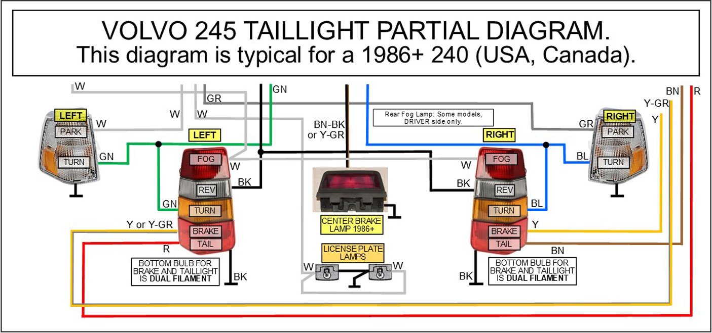
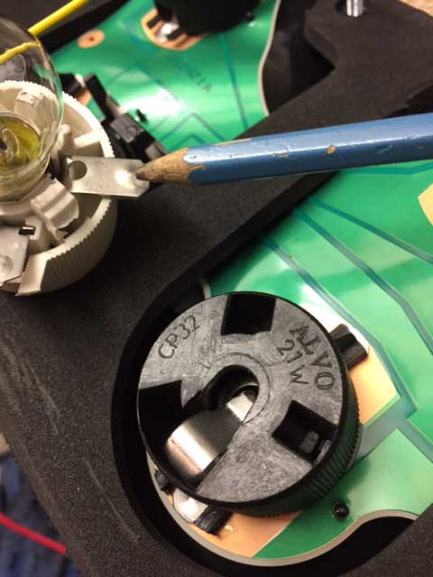
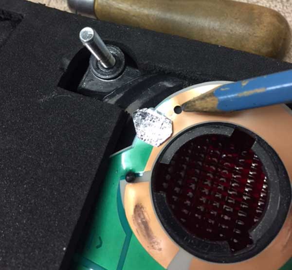
HARDWIRING GUIDE These two 8-pin connectors will be cut off and discarded during this procedure. Note that these wire colors may not be all the same as what you see, so check that. Volvo wasn't fully consistent about that and sometimes a wire color can fade and look different. 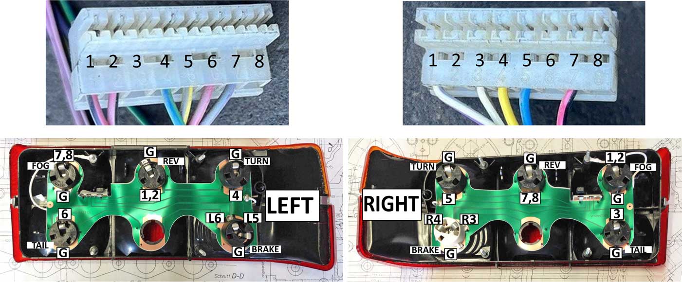 Left and right taillights are shown above. I have added numbered contacts for each bulb, which correspond to the pin numbers on the 8-pole connectors. If you see "L5" or "R5" the "L" or "R" refers to LEFT or RIGHT. This guide requires that you remove and discard the existing green printed circuit boards (PCBs). And as mentioned above, you will need to cut off the white plastic 8-pole wire connectors above. Then new wires will be spliced to the existing wires in your car coming from the body wire harness. Your new wires will then go directly to your existing bulb holders. So the old PBCs will no longer be used. Here's a general wire color guide below showing typical wire colors for early and later taillights. Sometimes you'll find different wire colors or maybe faded colors that look different. The listed wire colors in this image below are ONLY the 12V+ wires. Yes, sometimes Volvo used BLACK wires for POWER as shown below, so pay attention. These taillights also use some BLACK GROUND wires which are NOT SHOWN in this image. So since each bulb needs to have a ground, the GROUND locations (and positions for each bulb holder) will be noted in other images as GROUND or “G.” It bears repeating since people don't always read thoroughly: GROUND wires are NOT listed in this image below. 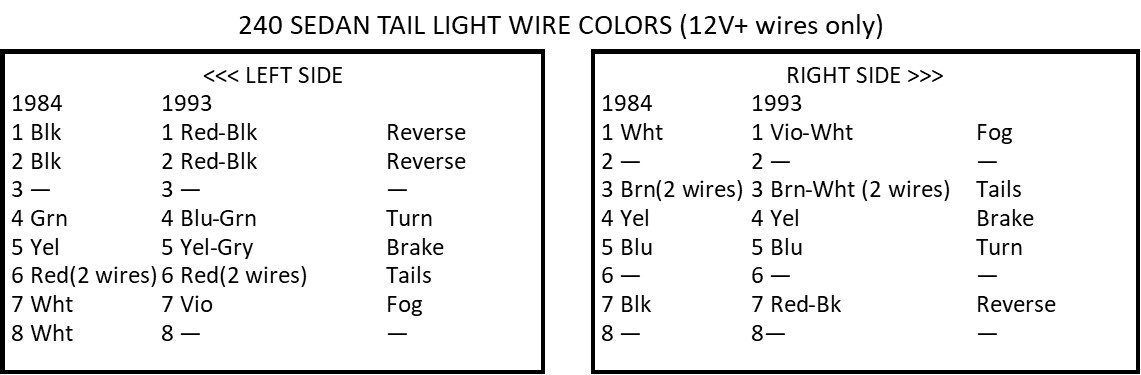 This guide applies to all 240s with 6-panel taillights. Keep in mind that there are some small wire color differences depending on the year up to 1984 and from 1985 to 1993. This guide will show how to wire the lights to work like these images. If your bulb designations are different from anything shown here, you can deviate from these instructions if needed and wire your bulbs differently if you like. If you're not sure, using the pin numbers shown in the above images is what I recommend. 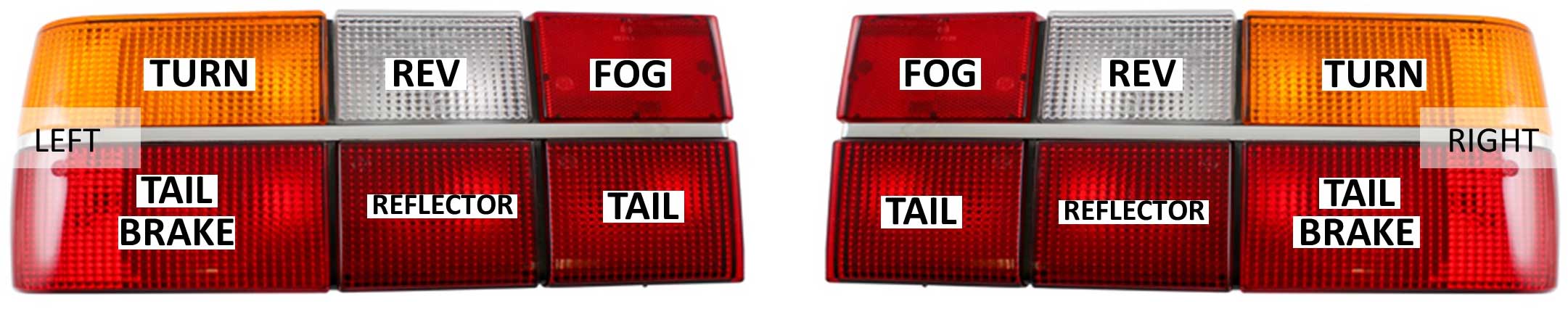 Your taillights will have these plastic bulb sockets (or bulb holders) shown below. There are two distinct types for different bulbs bases. Some bulb holders are black and some are white. This first one below is a TWO-contact bulb socket. The bulb base type base is often similar to universal type 1156, but the correct bulb will be a smaller 5 or 10 watt bulb (Osram or Sylvania 5007 or 5008). 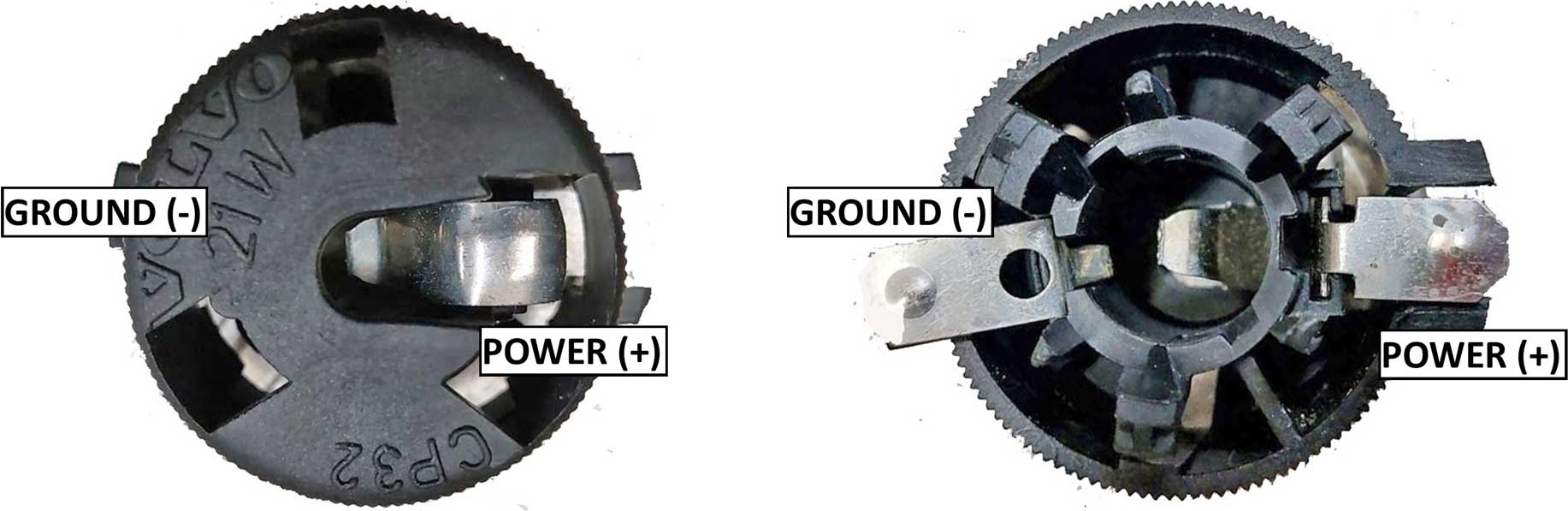 And this one is a THREE-contact bulb socket, made for dual filament bulbs. This bulb base type is for Osram 7225 or 7528 or a universal type 1157 bulb can be used here. 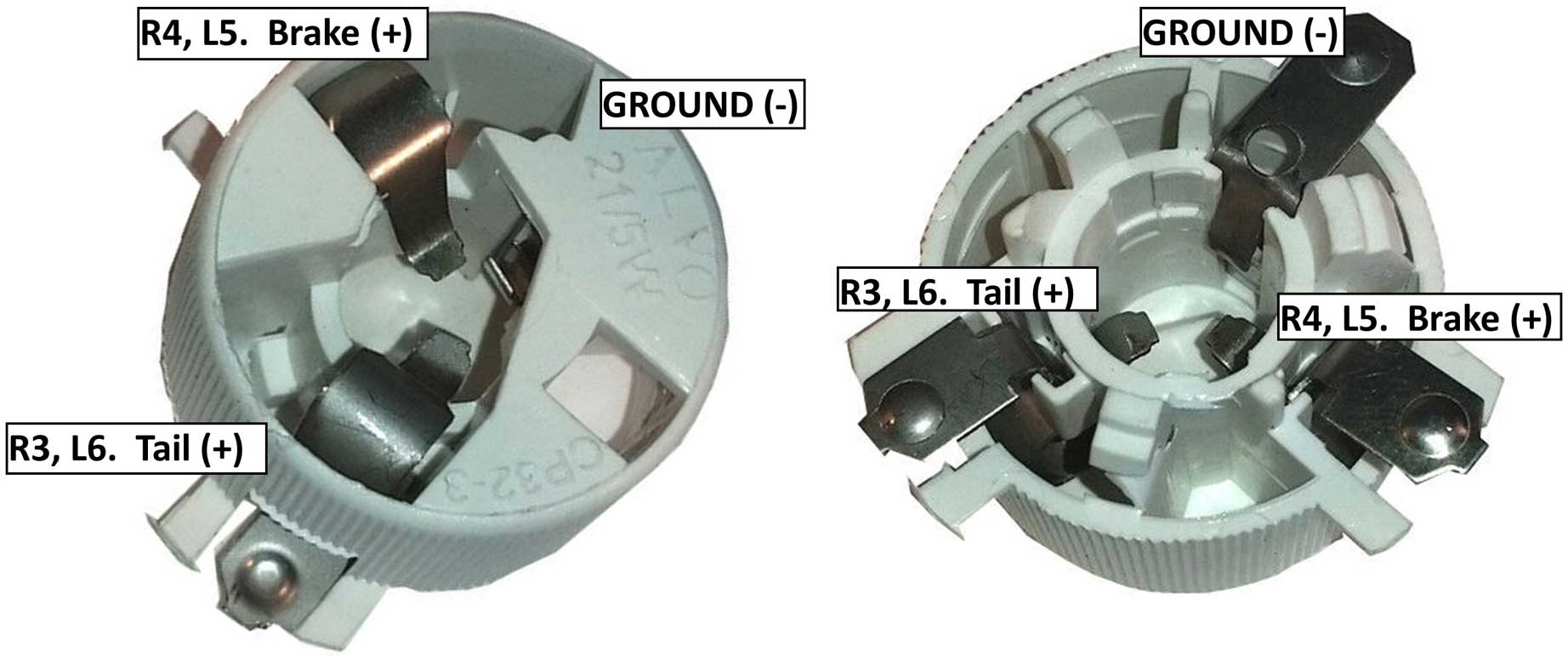 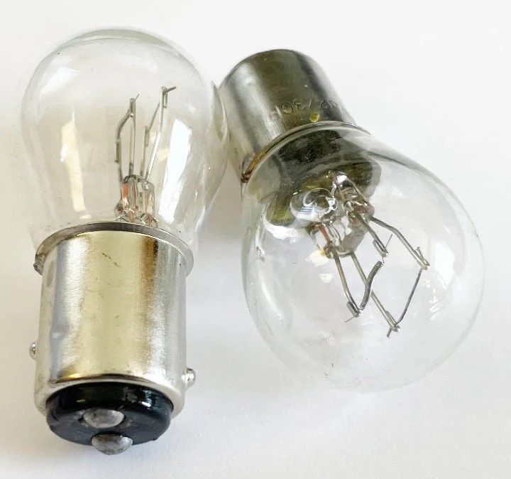 I want to point out there are multiple options when attaching wires directly to bulb socket contact tabs. 1. SOLDERING. NOT what I prefer. Solder is fragile and will break eventually. 2. Using CRIMP push-on terminals. Attaching a CRIMP TERMINAL to the bulb socket is my personal preference because it makes it less likely that connections will break off when changing bulbs. If you're using common .250 inch (6.3 mm) FEMALE crimp terminals, you'll need to TRIM the METAL TAB CONTACTS on the bulb sockets, because those contacts will be too wide to fit into the .250 inch female terminals. Trimming the contacts down can be done with sheet metal snips. I don't have a photo of that, but you can use your imagination. 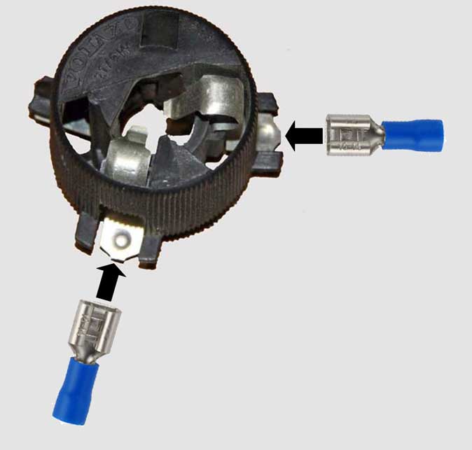 MY PREFERENCE: CORRECTLY SIZED .312 inch (7.9 mm) FEMALE TERMINALS are available, which will fit directly and slide onto each tab. These .312 inch (7.9 mm) terminals can be found in my page HERE. 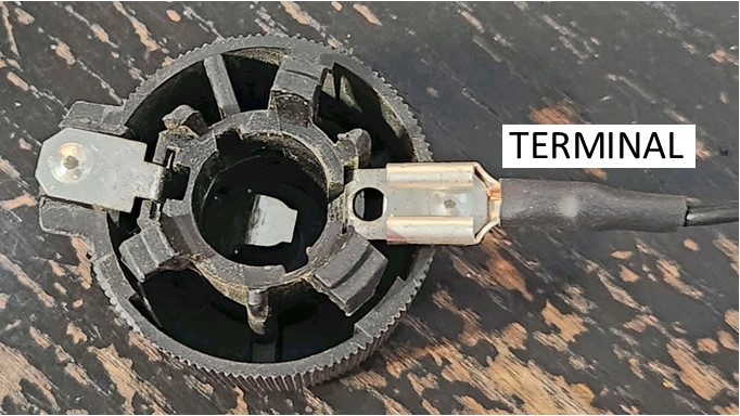 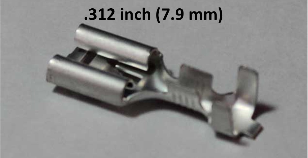 MORE RECOMMENDATIONS: You’ll discover that a little extra room is needed under the bulb sockets when you mount them into your tail lights after connecting the new terminals. So the metal tabs on the bulb sockets should be carefully bent away from the tail light to increase room slightly between the bulb socket and the taillight. 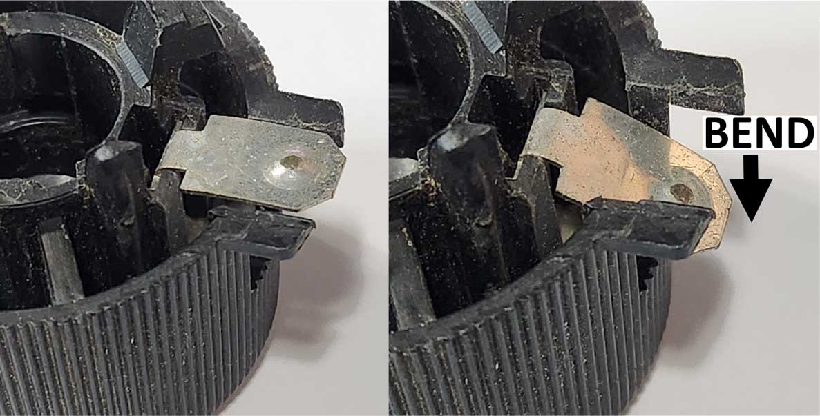 Keep in mind that the above photo is showing an exaggerated bend. You should start by bending just a little at first. You’ll know if it needs more bending when you try inserting and twisting the bulb socket into the taillight hole. If it’s too tight, it will need some extra room and the tab can be bent a little more. If it’s too loose, then bend it less. The bulb socket should be just snug enough to stay in place when you insert and twist it. You’ll also need to create some extra room on SOME bulb sockets. This will be near the tab as shown below. The extra room is needed in order to be able to bend the tab. Making room is done by trimming some of the plastic as shown below. Usually some small tin snips or wire cutters can do this. Or you can disassemble the bulb socket and grind or file the plastic. 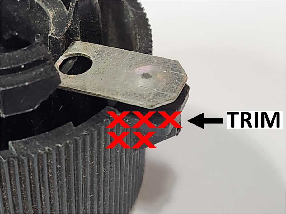 NOTE ABOUT REAR FOG LAMPS  Not all 240s were equipped with rear fog lamps. A rear fog lamp is a lamp that is activated with a switch on the dash. If your car DOES NOT have this, you may have the option of ignoring those wires or you may use bulbs in these positions for another purpose (such as another tail lamp). If you use this to add a rear fog lamp, note that in all U.S. 240's I've seen, the original setup used only ONE side (DRIVER SIDE), not both sides. A rear fog lamp is not very special. It’s just another bright bulb meant as a safety measure in heavy fog. It’s brightness is the same as a brake lamp bulb. Simply follow the wire connection guide for each wire color. And remember one black ground wire also goes to each bulb. After the wires are connected, install the bulb sockets into the respective holes in the taillights. A random example photo below. This installer used all one wire color for the power. Don't do this. I would try to find colors closer to what your original wire colors are. 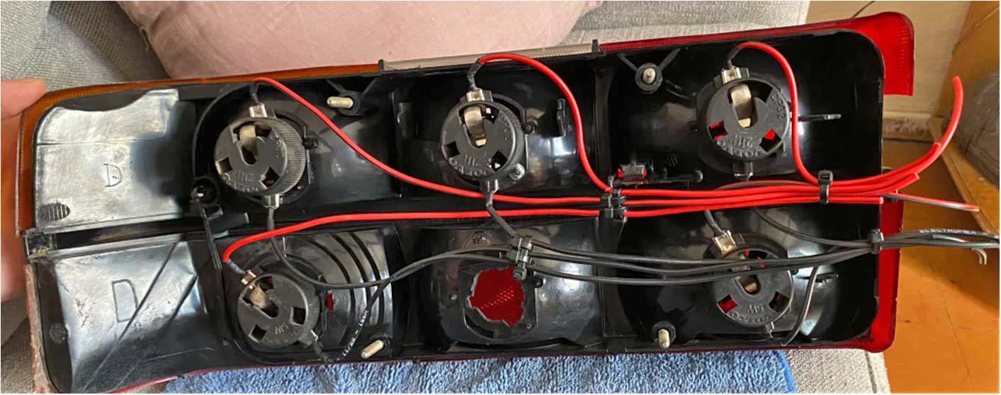 The hardest part about this project is figuring out what wires go to which terminal on which bulb socket. Before cutting any wires, It'll help a LOT to get a pencil and paper and start drawing diagrams of YOUR OWN wire colors and where they go. On your car you can use a test light or multi-meter set to continuity to trace all those colors to each bulb socket and each terminal on those bulb sockets. Then figure out and document which tab on each bulb socket should receive each wire color. Remember that some bulbs may be DUAL FILAMENT BULBS and those sockets have THREE contacts, two hots and a ground. SOME MORE 240 WIRING DIAGRAM EXAMPLES BELOW 0.75 mm wire is close to AWG 18-20. COLORS: BL = Blue; BN = Brown; GN = Green; GR = Gray; R = Red; SB = Black; W = White; Y = Yellow. Typical wire colors for 1979-84 240 
Typical wire colors for 1985-93 240 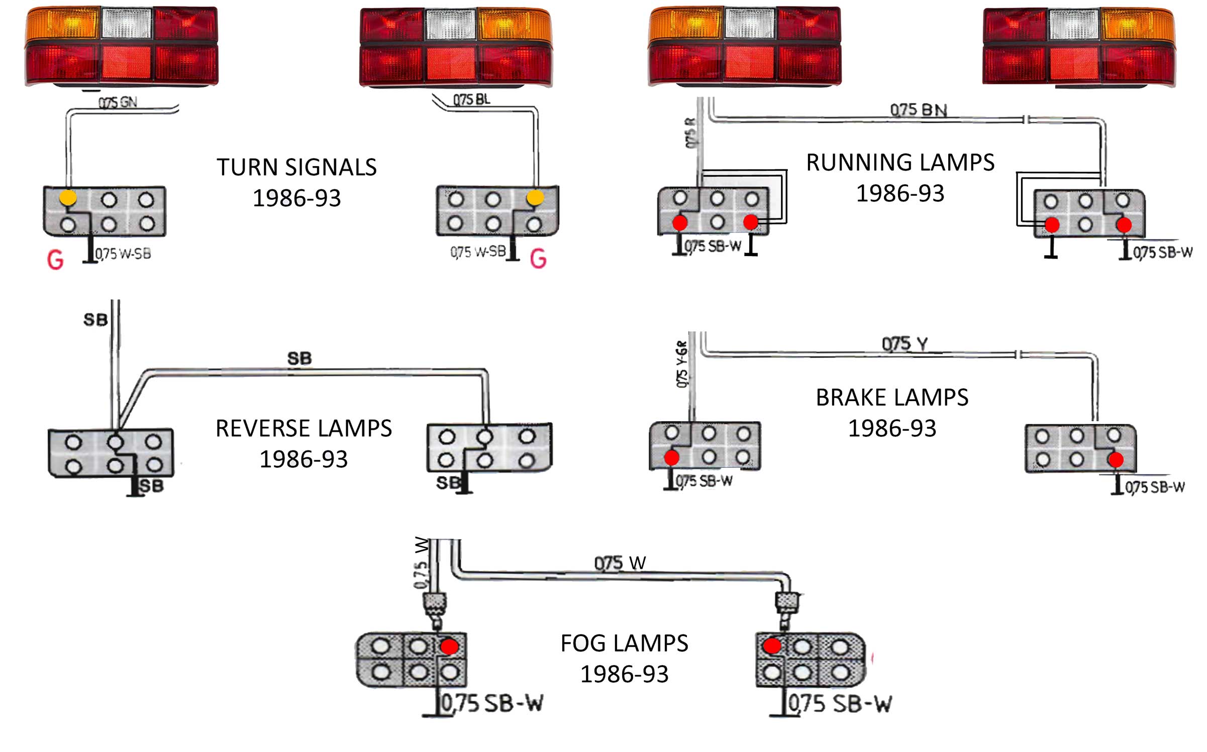 HELPFUL ARTICLES:
cleanflametrap.com/tony/tail_light_color_code_v0.htm
youtube.com/watch?v=LFouOkHW8ho brickwalla.wordpress.com/2011/11/16/hard-wiring-my-tails turbobricks.com/hard-wiring-240t-tail-lights.63287 Here's a hard-wiring video that will also help give you the general idea. https://www.youtube.com/watch?v=pQRtz5mD8Aw |
   |
 If you need to tint AMBER, I have not tried any transparent amber paints yet, but I have heard of good results from the below Tamiya TS-73 Clear Orange for Plastics. I have also read that you can get good results from a transparent STAINED GLASS paint. Krylon also makes such transparent paints in aerosol in ORANGE and RED. I have not used those yet. |

|


 alternators are known for poor voltage.")


