|
2 4 0 T U R B O . C O M D A V E ' S V O L V O P A G E
|
||||||||||||||||||||||||||||||||||||||||||||||||||
|
2 4 0 T U R B O . C O M D A V E ' S V O L V O P A G E
|
||||||||||||||||||||||||||||||||||||||||||||||||||
| This is the Headlight RELAY Page |
| f
you have any comments or if you can improve this
information, please feel free to email. CONTACT |
More about this early relay can be found in Ron Kwas' page: www.sw-em.com/Bistable_Control_Relay 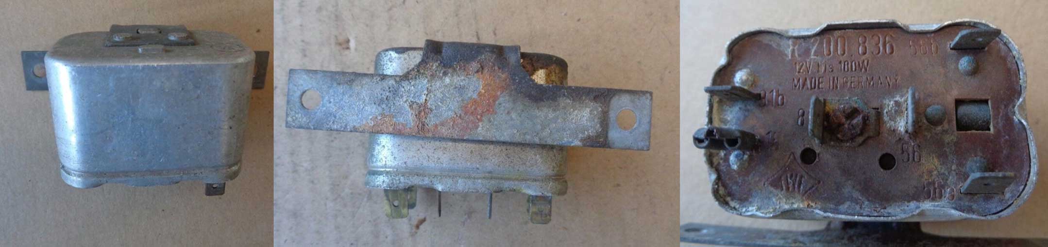 |
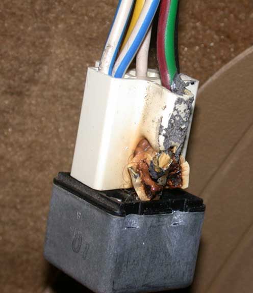
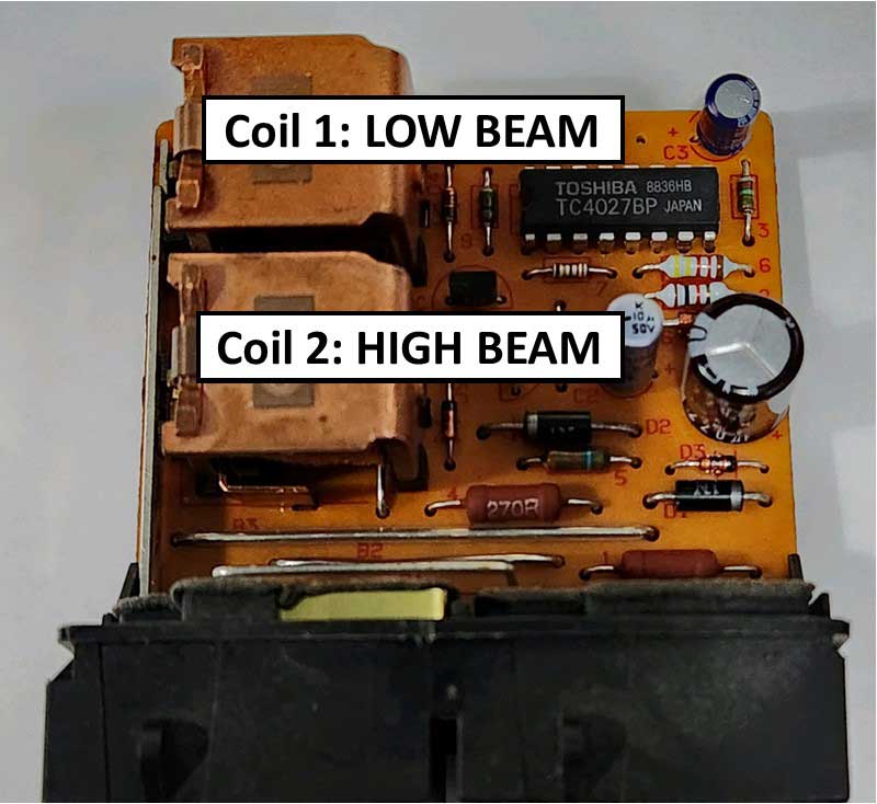
The internal function of this relay is COVERED IN DETAIL HERE. Volvo PN 1307991 Headlight Step Relay. 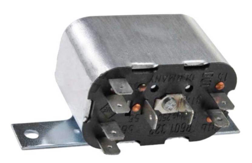 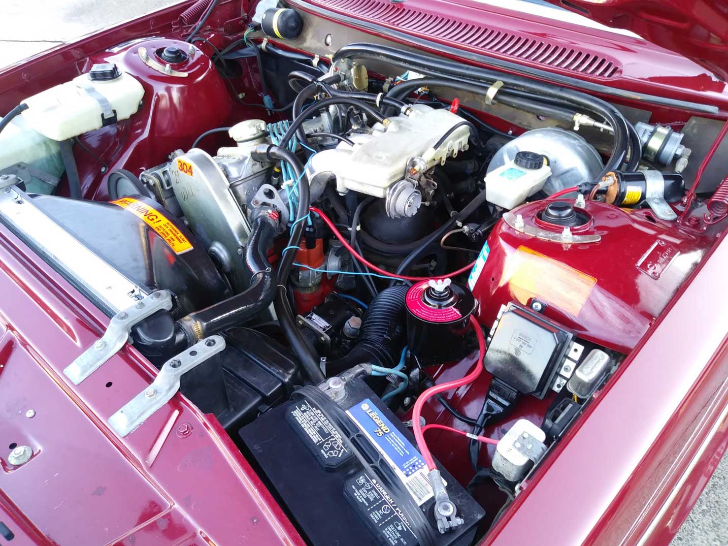 Sometimes these relays will fail. I had one fail one time many years ago in an '83 240. The failure was an internal soldered junction that broke the solder joint. This disabled the low beams. I was able to disassemble it and I repaired it easily with a soldering iron. |
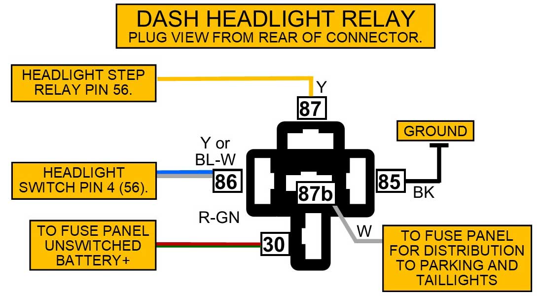
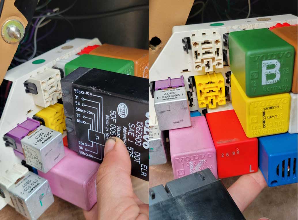
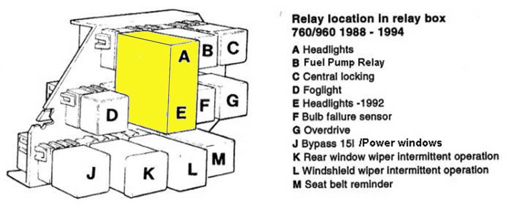
Here's a look at the main headlight relay in the 240 center dash behind the center vents.  This MAIN dash relay is found NEXT TO and to the LEFT of the POWER DOOR LOCK RELAYS, which can be seen in this photo above. This photo was taken with the entire dash removed. Removing the dash is not necessary to access these. You should be able to get to these relays by removing the center air vents and by pushing the inner plastic air duct out of the way. Or by removing the center dash console as shown in the below VIDEO. Volvo didn't make it very easy to access these. Here's a nice video showing how to locate and change this center dash main headlight relay: https://www.youtube.com/watch?v=G9wftGCBWXc 240 Relay Locations PDF below (from the 1993 greenbook diagram). Look for Relay 124 for the Main Headlight Relay. 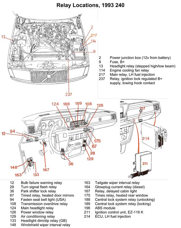
|
|||||||
|
|||||||
I created this detailed 1984 240 function diagram below so that almost ALL circuits and connectors and all connector pins can be seen. Please email if you have any questions or corrections. Click image for larger, high-resolution photo. 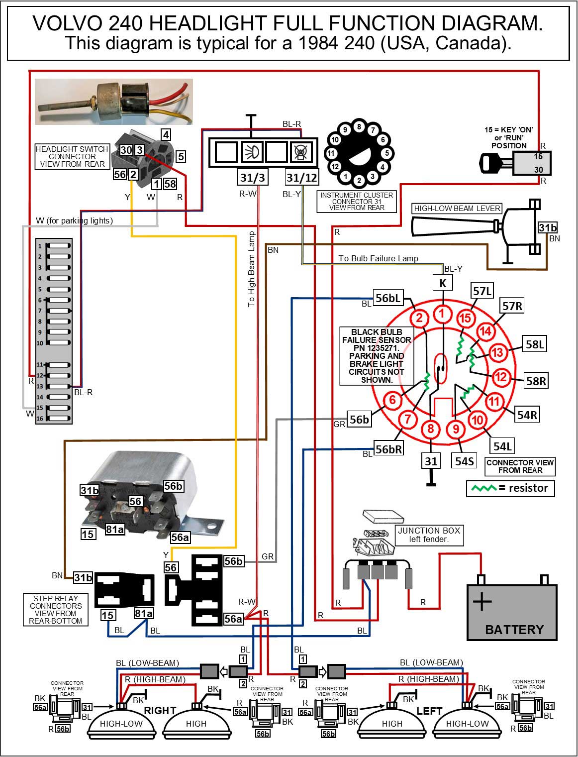 I created this detailed 1986 and later 240 function diagram below so that almost ALL circuits and connectors and all connector pins can be seen. Please email if you have any questions or corrections. Click image for larger, high-resolution photo. 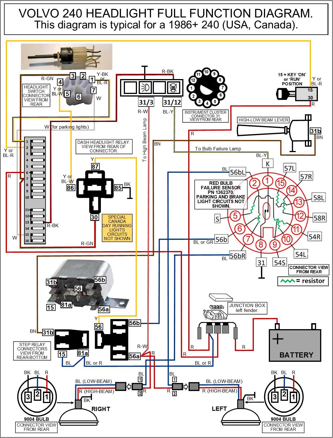 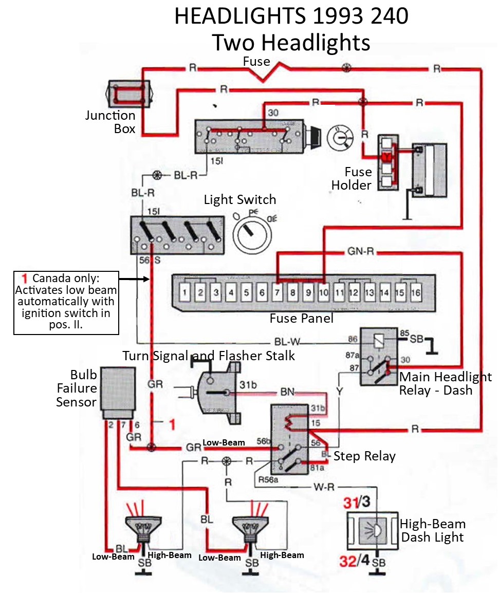
|
  I
have owned a number of Volvos
over the last 35 years and my
current 240 is 40 years
old. It almost never has
electrical problems. Nothing
like the endless numbers of
other 240s out there that I hear
about so often. What's the
difference you ask? The
main difference is that my 240 has
been always garaged all of its
life. Why is that
important? Because leaving
any car out in the open elements
for years and years slowly
introduces corrosion to grounds
and power connections until
things begin to go wrong. I
have owned a number of Volvos
over the last 35 years and my
current 240 is 40 years
old. It almost never has
electrical problems. Nothing
like the endless numbers of
other 240s out there that I hear
about so often. What's the
difference you ask? The
main difference is that my 240 has
been always garaged all of its
life. Why is that
important? Because leaving
any car out in the open elements
for years and years slowly
introduces corrosion to grounds
and power connections until
things begin to go wrong.
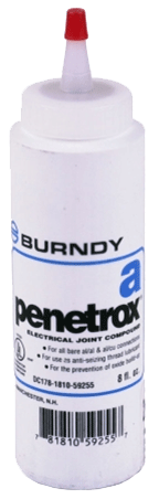
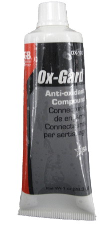
So if you own one of those cars that has been outside forever, it's not too late. You can still clean as many grounds and electrical connections as possible. And while you're at it, I strongly recommend that you smear a little anti-corrosive zinc paste on those connections. Many people in the Volvo community are already familiar with Ox-Gard, which does a very good job. The below information was contributed by Ron Kwas and should come in very handy to old Volvo owners: Anti-Corrosive Zinc Paste (a generic name for zinc dust contained in a grease) was originally developed for and later required by electrical codes for use on aluminum to copper electrical connections (or other dissimilar metal connections). No, it's not the same as Dielectric Grease, which is often incorrectly recommended. Dielectric Grease can offer some protection in the form of encapsulation from moisture, but it also carries with it the potential disadvantage of locking in moisture or existing corrosion which may have already begun forming. Anti-Corrosive Zinc Paste (ACZP) is the next evolution of the encapsulation principle, because zinc (the lowest on the Galvanic nobility chart) neutralizes corrosion on a micro-scale to truly protect connections on a long-term basis during the encapsulation, INCLUDING an added protection from corrosion which may have begun to form in that connection. Ron Kwas uses and recommends Penetrox A (by Burndy). Many Volvo fans are familiar with Ox-Gard, which is a similar zinc compound. Ron and I are huge advocates of treating ALL electrical connections on our cars (except of course High Voltage Ignition connections) with a suitable version of this material. You can learn more about this stuff at Ron's page here: http://www.sw-em.com/anti_corrosive_paste.htm |
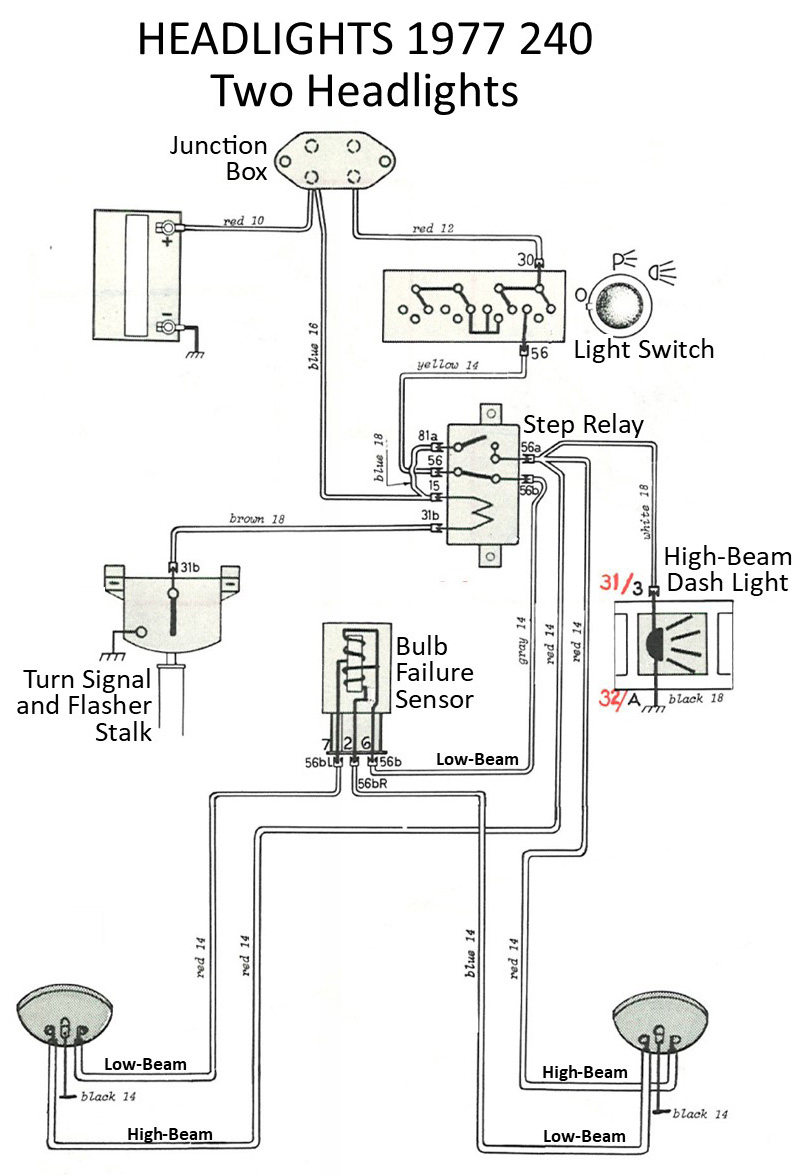
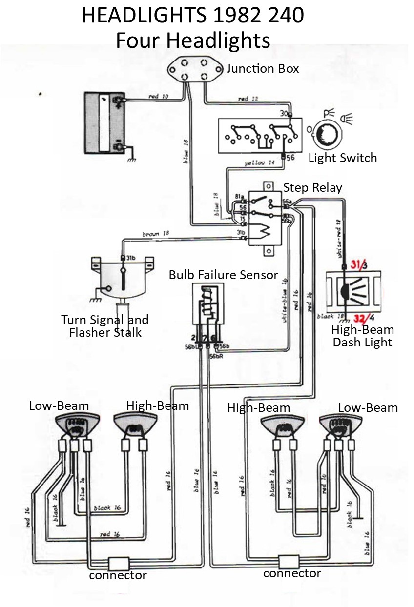
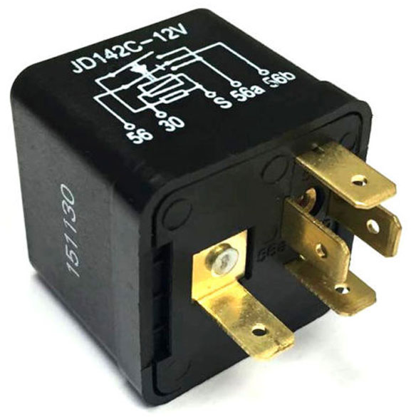
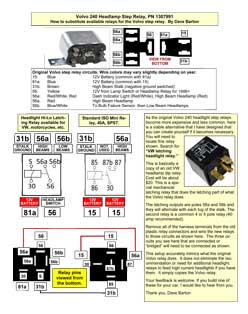
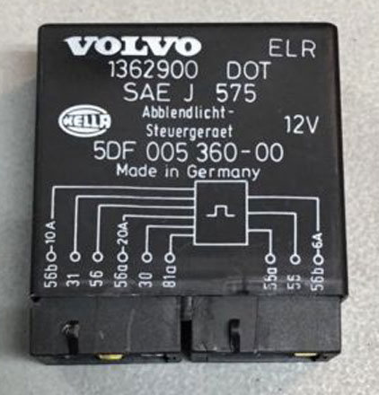
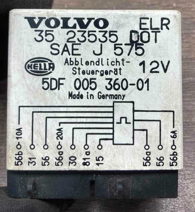
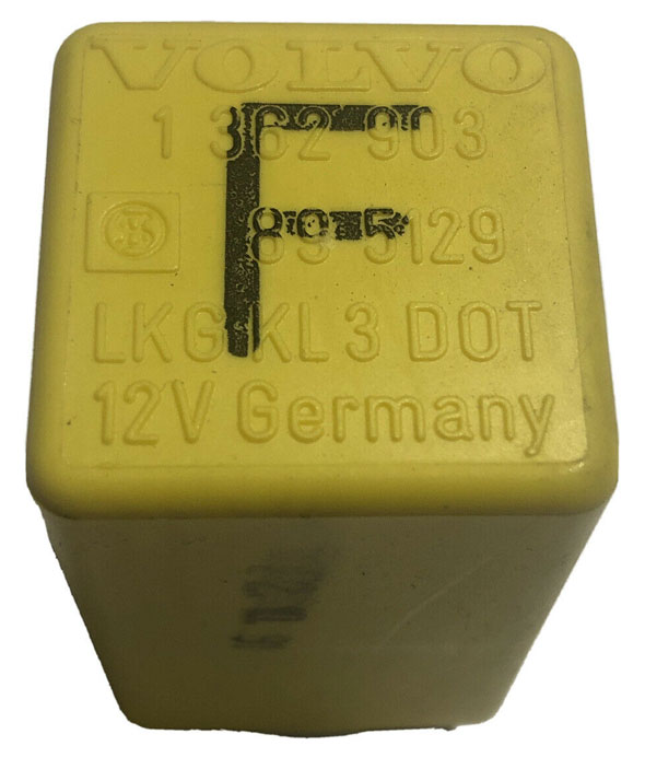
VOLVO PN 1307991.
This step relay is found in the Volvo 240 from 1975 to 1993. It will be seen under your hood on the LEFT inner fender, except for the 1993 model, where it was switched to the RIGHT inner fender. 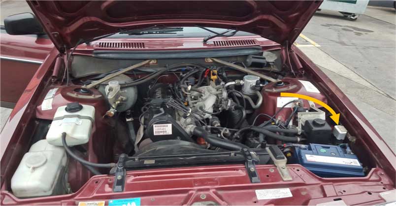
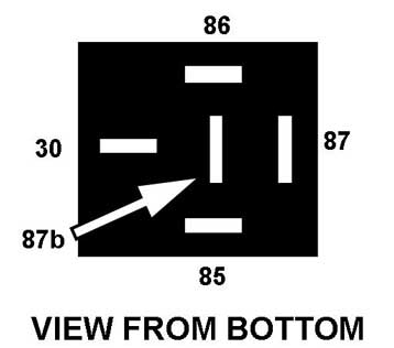
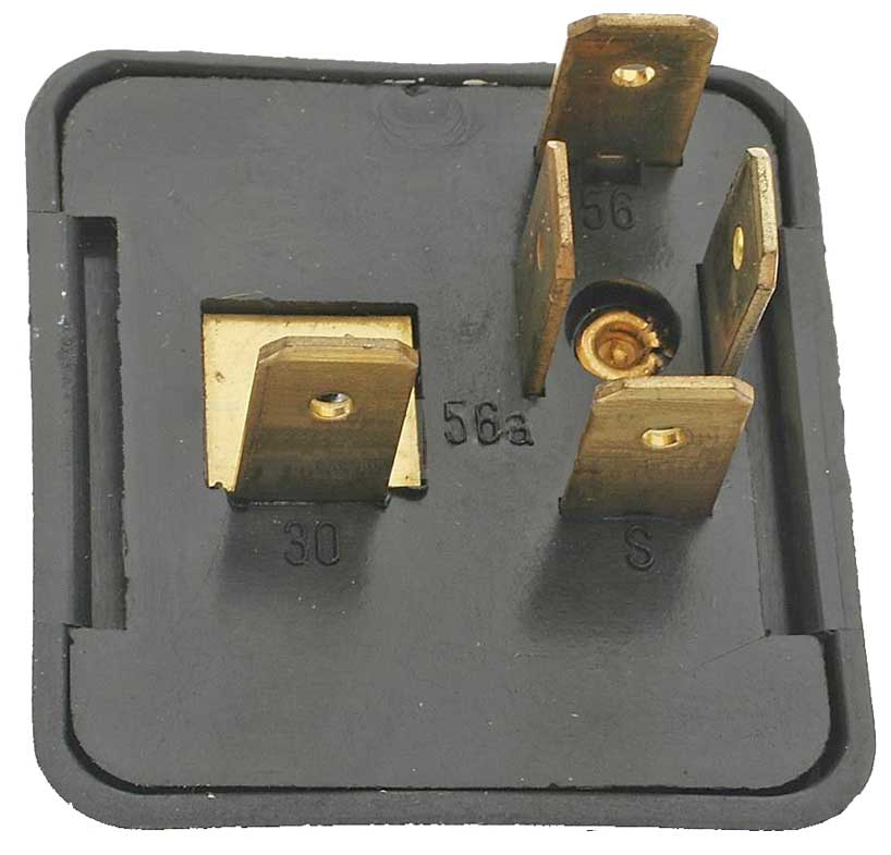
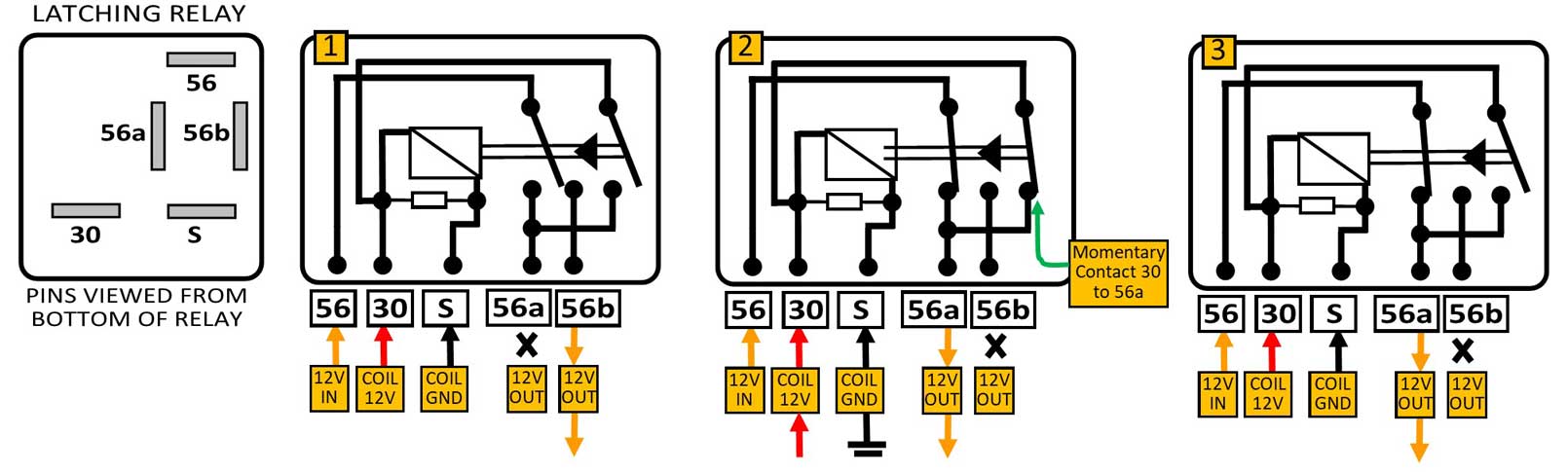
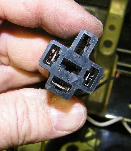
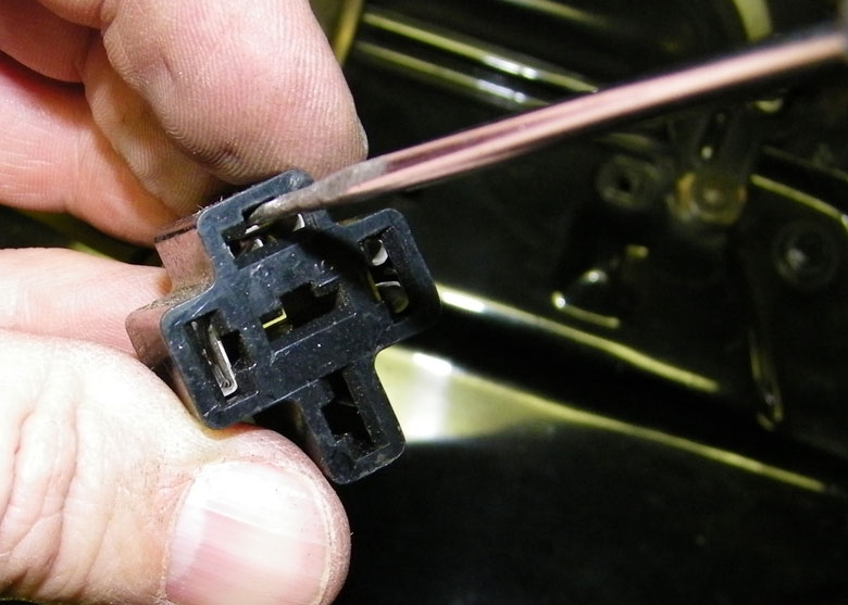
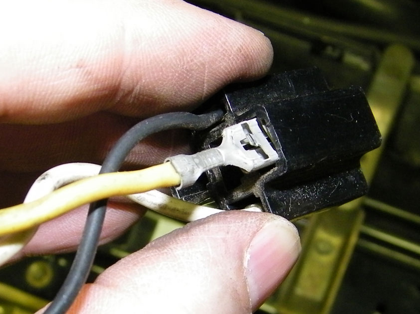
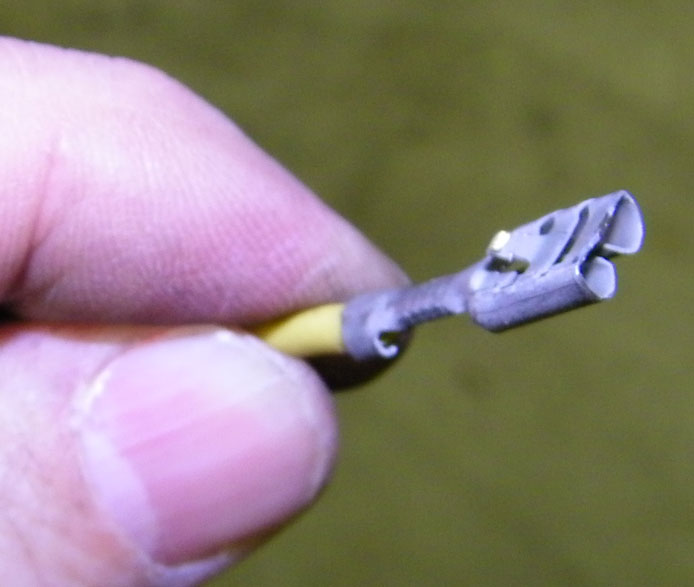
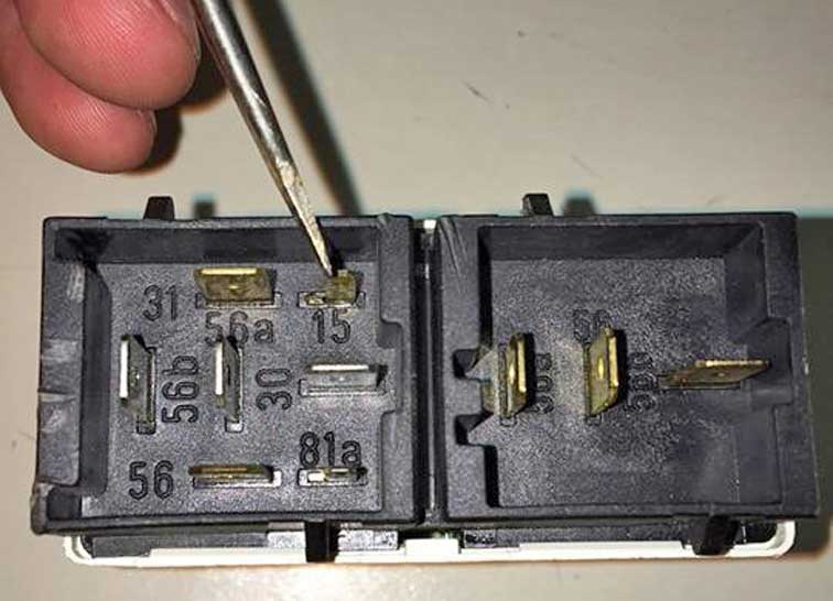
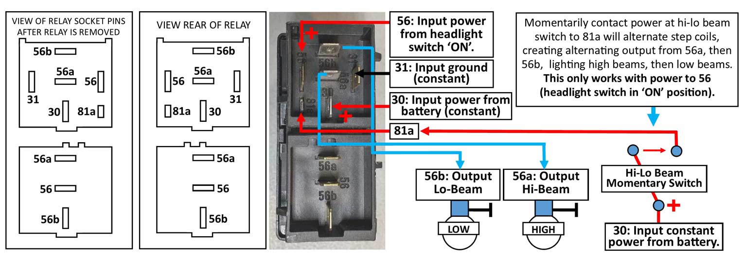
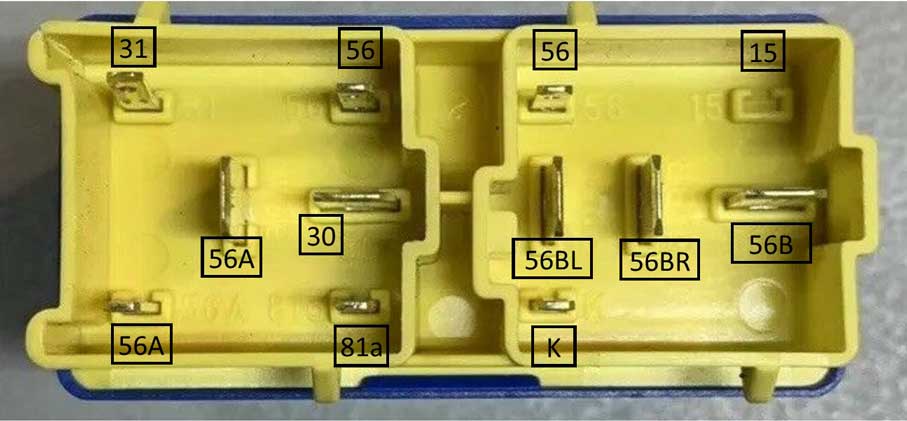
This relay was made in two different versions (using the same part number). Both versions function exactly the same and both are interchangeable. The EARLY version can be identified below with two less contacts. The extra contacts in the LATER version do not change the function at all. It just adds redundant contacts. 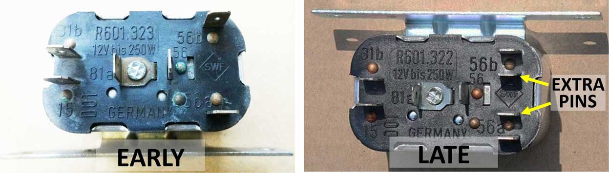 These two versions are interchangeable, however keep in mind that if you use an early relay on a later car AND your car just happens to NEED those extra two contact pins, you'll need to re-wire those contact pins in your car to the two outside pins. MOUNTING BRACKET FLIP-FLOP CHANGE If you're observant, you'll notice that the mounting bracket on a later relay is on the OPPOSITE SIDE. This doesn't affect the function, but it might affect the harness plugs, because if you use a newer relay in an older car, the harness plugs will need to be twisted 180 degrees to work. That will add unwelcome stress on your wires. A simple solution is shown below. It's a very simple task to pry open the crimps and remove the top outer housing. This is NOT hard to do. Then the housing can be turned 180 degrees and re-installed onto the relay. This literally takes 30 seconds. 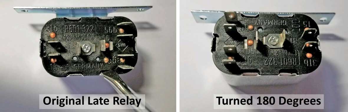 Step Relay LATCHING Function Explained This step relay has a LATCHING function. A latching function works like this: You can click and release a momentary button or switch (in this case it's pulling back on the 240 high/low beam lever) and the relay will then LATCH (or lock) in one position or another. It reverses with each pull of the lever. So with this step relay, one click latches "ON" the low beams. And another click latches "OFF" the low beams and latches "ON" the high beams. In a 240 the latch function is activated by a GROUND signal, which is created by pulling the high/low beam lever. Here's a short video on the step function between high and low beam.
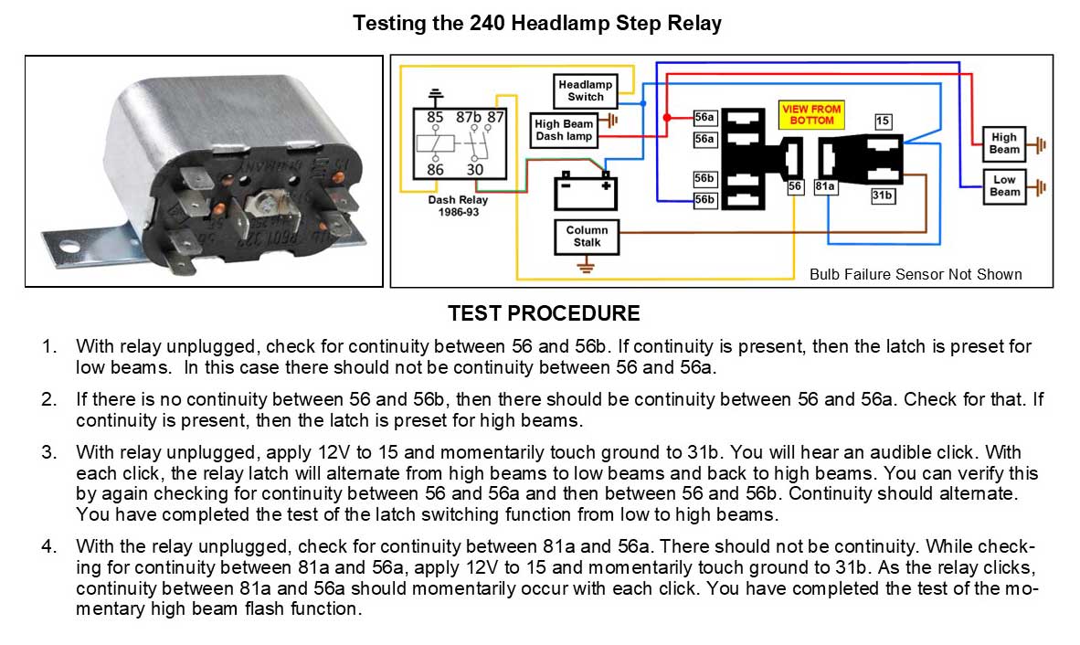
240 Step Relay Function and Testing 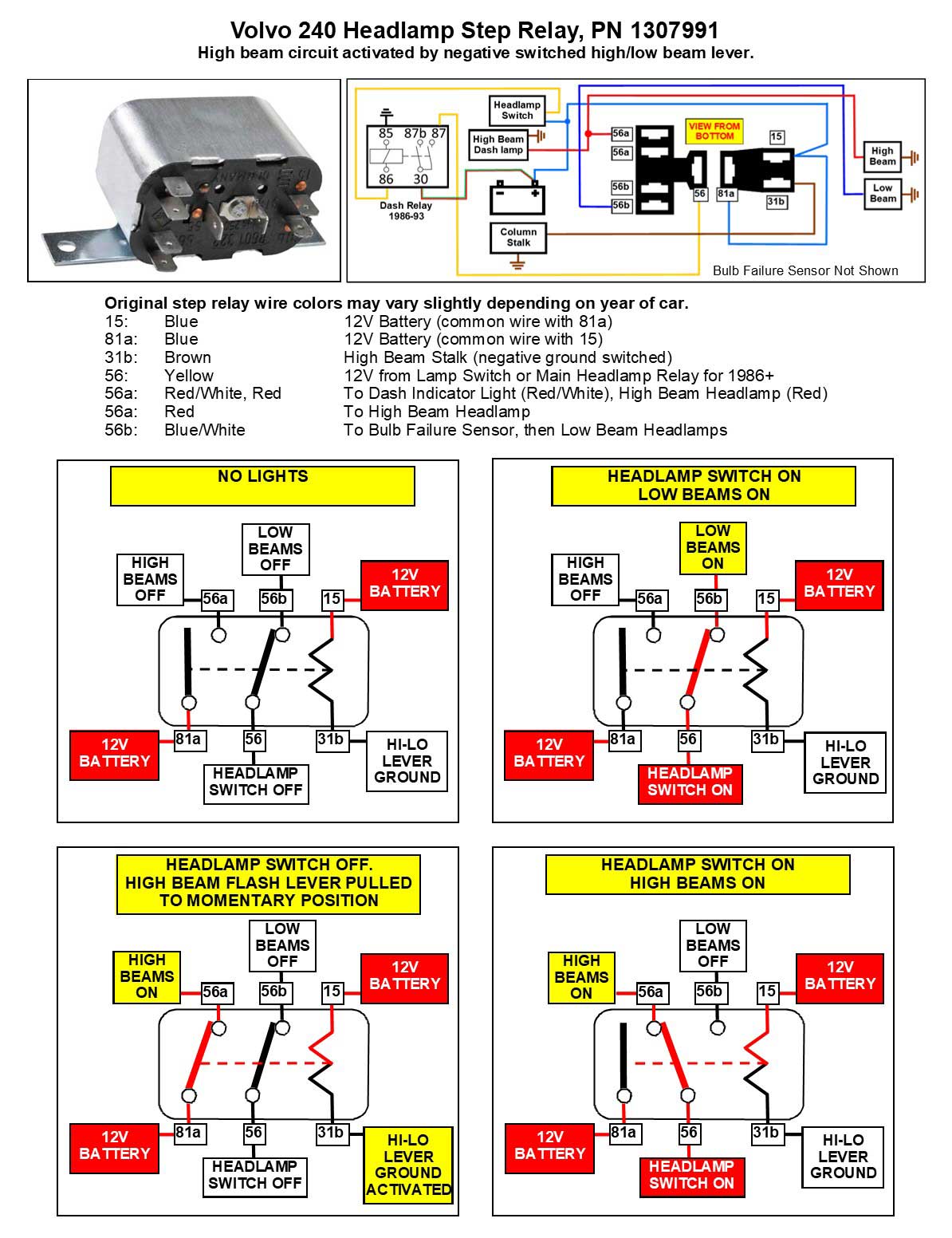
 I have created the below PDF if needed (same info as shown above). https://www.davebarton.com/pdf/headlightsteprelay.pdf 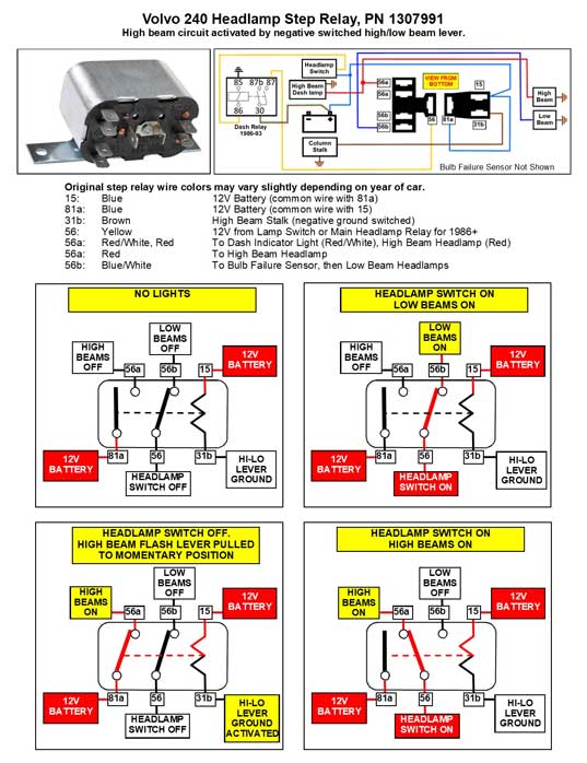
|
| How to Use
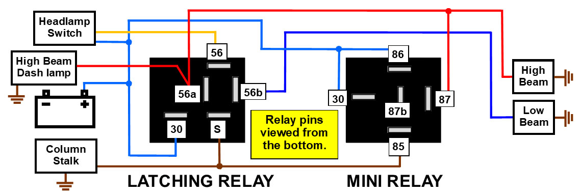
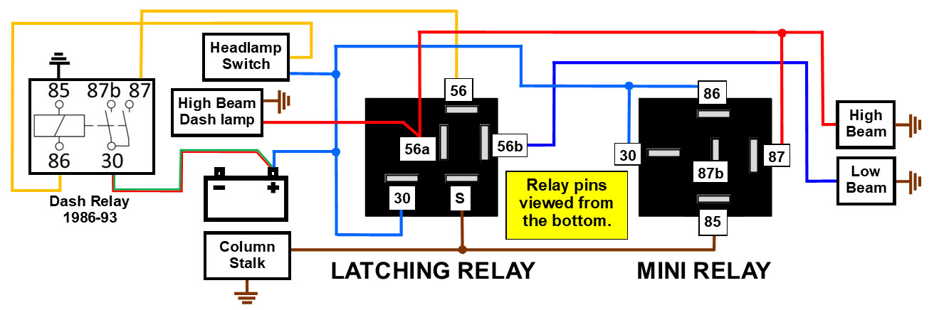
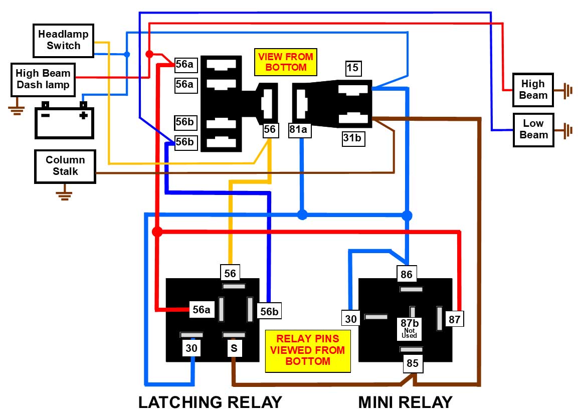
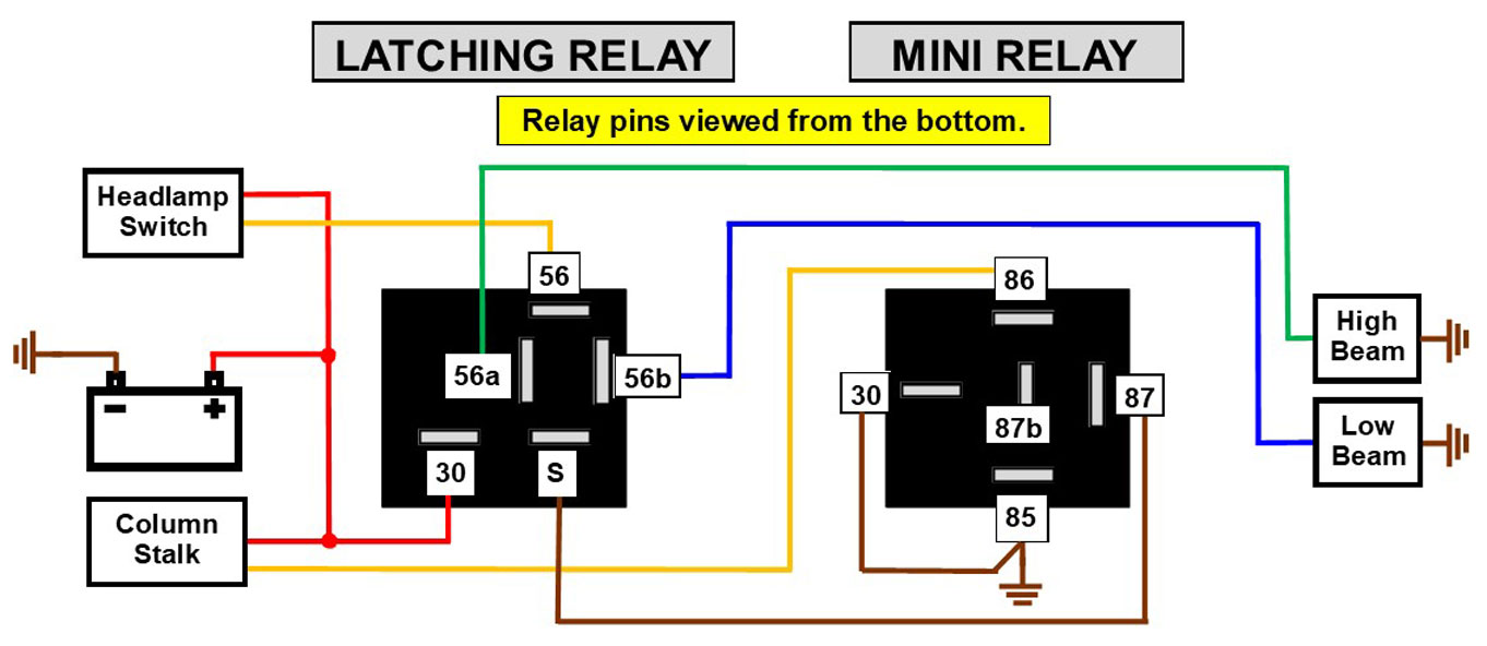
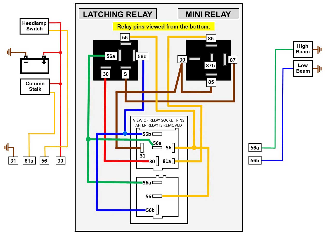
Commonly Available Relays to ELIMINATE or REPLICATE your Volvo 240 Headlight Step Relay. |
This modification will not be
necessary as long as your step relay keeps working. But if needed, this
modification will accurately
reproduce the functions of the original Volvo step
relay. It simply copies and can replace the Volvo step
relay and connectors if necessary. This does not eliminate any need
or recommendation you may have for installing additional headlight
relays to feed high current headlights if you have them.
Feel free to add those if needed.
CONTACT |
|||||||||||||||||||||||||||||||||||||||||||||
|
This
is a good project for anyone with any older Volvo, especially if you
have or want to to upgrade to brighter bulbs or headlights.
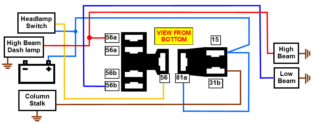
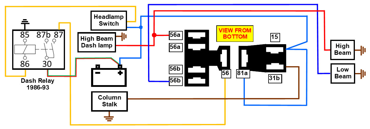
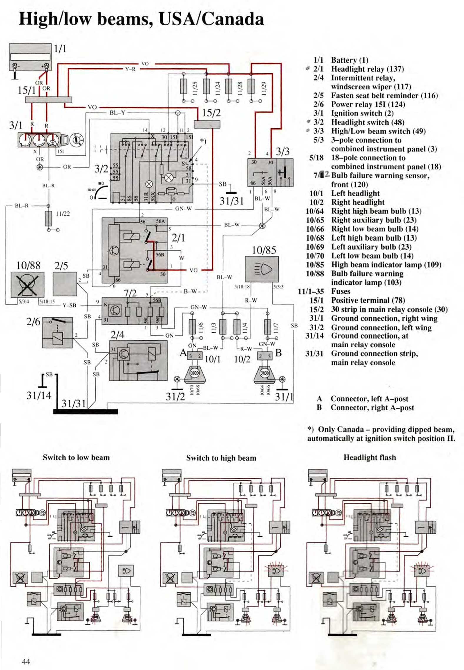
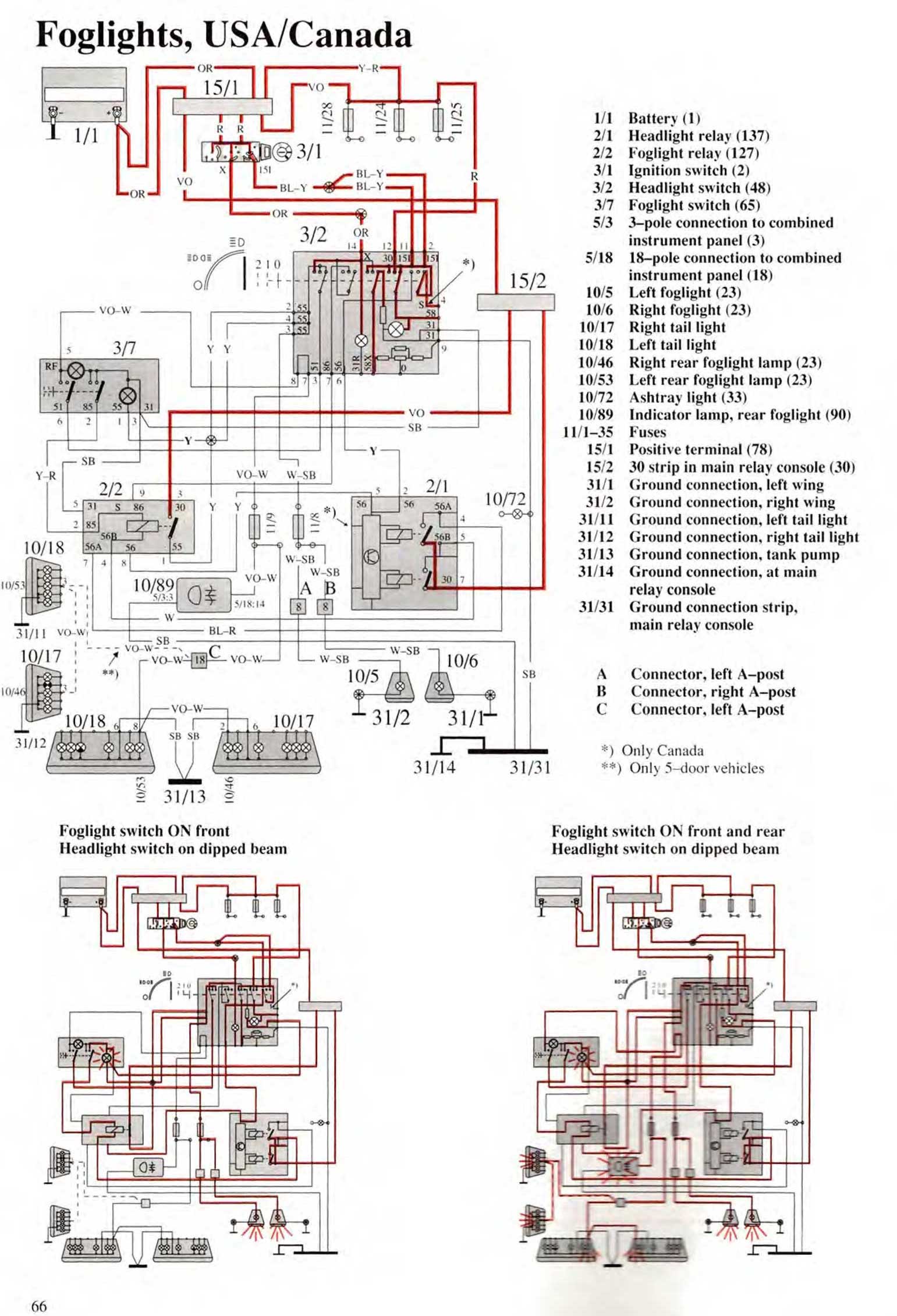
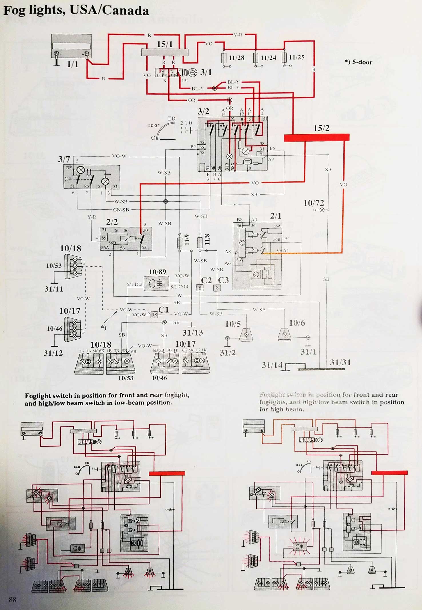
For the best info I know, begin reading Daniel Stern's page on this subject. He also has several useful diagrams for designing and building your own relay harness. http://www.danielsternlighting.com/tech/relays/relays.html Here is a Volvo 240 specific diagram showing how an upgraded relay harness can be made. The relay triggers (relay are connected to and triggered by 56a and 56b) can be taken from the fender harness connectors or if you want to bypass the bulb failure relay, you could take those triggers from terminals 56a and 56b directly from the 5-pole headlight step relay connector. 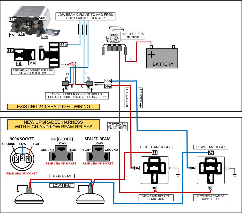 This diagram assumes you would use one relay to control both low beam headlights and another relay for the high beams. The above 9004 bulb socket came on all 1986-93 USA 240s. A European E-Code headlight will typically use an H4 bulb. UPDATE 2018: Wagonmeister is offering ready made upgraded 240 headlight relay harnesses, like this one below. 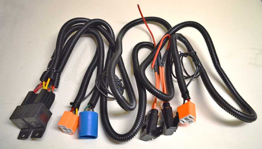 |
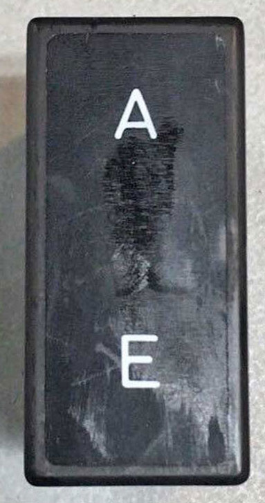
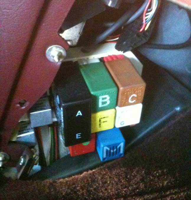
This "A-E" relay is PN 1362900 and has been no longer available new for many years. Used relays like this one have been known to show up online for OVER $200! Since I didn't have any 760 or 900 Volvos to test, this project has relied on the help of a few owners of those cars who helped with testing. My goal was to work out a similar solution to offer a way to ELIMINATE THIS RELAY in a similar way as the 240 step relay can be eliminated if needed. This project was a success.
|
| Bosch Terminal Designations |
|
| If you've ever wondered where all of those relay and component terminal numbers came from, they were standardized by Bosch and a list of those numbers and their meanings can be found at the following link: http://dastern.torque.net/techdocs/boschterm.html |
|
|
||||
| davebarton.com |
prancingmoose.com |
240turbo.com |
Special Emblems |
|
| Prancing
Moose Stickers |
Volvo
Stickers |
Body/Chassis/Engine
Labels |
240 MODS and FIXES Page | |
| Other Car Brand
Stickers |
Steering
Wheel Labels |
Center Cap Labels/Overlays |
Cool Volvo
Products |
|
| Grill Labels/Overlays |
Volvo Wire
Harnesses |
Conversion Harnesses |
Harness
Parts/Connectors |
|
| Volvo Relays |
Coil Repair
Harnesses |
240 Window
Scrapers |
740/940
Window Scrapers |
|
| Adjustable Voltage
Regulators |
Horn Buttons |
240 Odometer
Repair |
740 Odometer
Repair |
|
| Volvo Gauge
Faces |
740
Turbo/Boost Faces |
240 Black Door Vinyl |
850 Odometer
Repair |
|
| ALTERNATOR Page |
240 Power Mirrors - Switches |
240 Oil Cooler Page |
240 Fuse Panel Page |
|
| Group A
Racing 242 Turbo Page |
240 Hydraulic Clutch | Fuel Pump RELAY Page |
240 Headlight RELAY Page |
|
| Used Parts & Extra Stuff for sale |
CRIMPING Page |
240 Ignition Page |
240 Headlight Page |
|
| 240 Gauge Electrical Diagrams | 240 REAR END Page | Yoshifab Catch Can Install | 240 TAILLIGHT Page | |
| Side Marker
Lights Page |
Gentex Mirror Upgrade | Yoshifab Drain Tube Install | Modified 240 Favorites | |
| SoCal Salvage Yards | Unleaded Racing Fuel | B26FT Stroker | Dave's 245 Spec Page | |
| 240 SUSPENSION Page | 240 Lowering Page |
240 Windshield Page |
240 WIPER Page | |
| 240 BRAKES Page |
240 Dash Top Gauge Pod | Cadillac 4-Note Horn Install | 240 DYNAMAT Installation | |
| 4 Speed Fan
Controller |
Electric Cooling Fan
Page |
BRUSHLESS Cooling Fan Page |
Tropical Fan
Clutches |
|
| 240 AC Page | "KOMFORT BLINKER" Upgrade | T5 Trans Conversion Page | 240 Engine Mount Page | |
| 240 VIN Page | Stepper Idle Valve Page |
Vacuum Diagrams | 240 HOOD Page | |
| 240 Exhaust Page | 242 Power Vent Window Project |
EFI Volvo Pin Function Diagrams |
Favorite Links | |
| R-Sport
Apparel |
Prancing
Moose Apparel |
Volvo Meet Photo Albums | Texas Volvo Meets and Events | |
| Ordering Instructions | Policies | PAYMENTS Page |
Mojave Road Trail Map Page |
|
| Returns | Shipping | Shopping Cart Troubleshooting | Contact Us |
|

|


 alternators are known for poor voltage.")


