|
2 4 0 T U R B O . C O
M D A V E ' S V O L V O P A G E
|
||||||||||||||||||||||||||||||||||||||||||||||||||


 alternators are known for poor voltage.")


4-Speed Cooling Fan Controller Project
If you have any questions, fire away: CONTACT Before I published this page I began a discussion at forum discussion about this project, which you can find here. 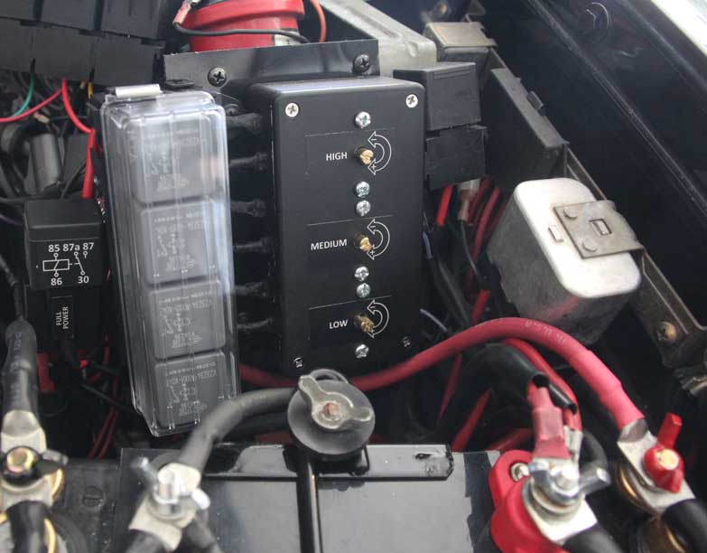
|
I began this project in summer 2016 out of frustration.
I had experienced successive failures of a number of commercially available brushed fan controllers over the years (Delta Current Control and Flexalite). The failures were partly because I was using a high-amp Ford fan and it was too much for those fragile controllers. So this project gave me a challenge to see if I could build something BETTER or STRONGER on my own. I wanted it to do THREE THINGS:
But then I saw this . . . . . 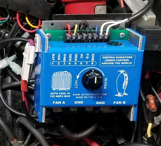 In 2018 I discovered this line of high-amp PWM brushed fan controllers. So I tried one and then retired my home-made 4-speed controller. CLICK HERE TO SEE MY INSTALLATION OF THIS NEW PWM CONTROLLER. This new controller was flawless for many years until I decided to move away from brushed fans. |
||
|
|

|
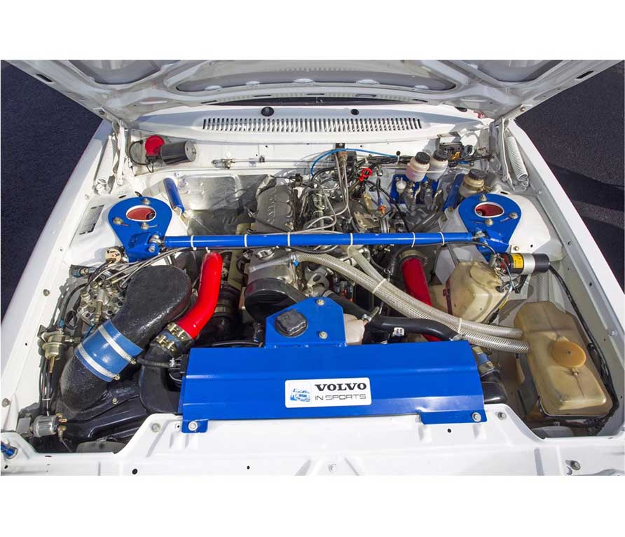
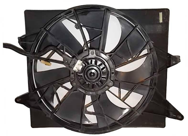
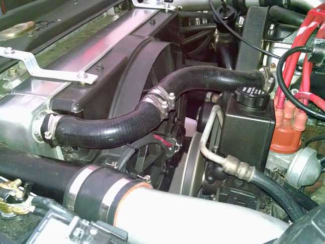
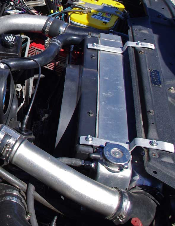
So as you may have noticed, I'm using a Lincoln Mark
VIII brushed fan and shroud (1997 model)
mounted on a large 26 inch wide Griffin aluminum
radiator. I decided to try building my own
fan controller using simple, reliable relays to see if I could
make it work the way I wanted and I wanted one
that would LAST.
 There are people who will warn you that using relays to run a fan is risky, since relays can be slowly damaged from turning on high-current motors over and over. This may be true, but It's my opinion that it would take years and I doubt the risk would come anywhere close to having a high-tech controller meltdown every 1.5 to 2 years! More general info on
the installation of my Mark VIII fan and Griffin
radiator in my Volvo 242 Turbo can be found in my
Cooling Fan
Project Page at:
|
|
|
|
|
|

| FOUR SPEED RELAY FAN CONTROL EXPLAINED NOTE: I used the first diagram below when completing this project. I have not tried the alternate diagram I later added below. This setup works for any 1 or 2-speed cooling fan. If a 2-speed fan is used, I suggest using the high speed circuit on the fan. I opted for using multiple adjustable temperature probes as shown. The probes can be mounted onto or inserted into radiator fins or into a coolant hose for direct coolant contact. This allows you to custom set each speed setting to a precise temperature set point for your car. Starting and fan speed ramp-up is smooth when starting at a low speed. Of course you may instead use any type of temp senders you like and mount them where you like, such as in the radiator, engine or hose, however I don't know of any others that are so simple AND ADJUSTABLE besides those I show below.
 |
|
This is an alternate diagram that I made later, which I liked better.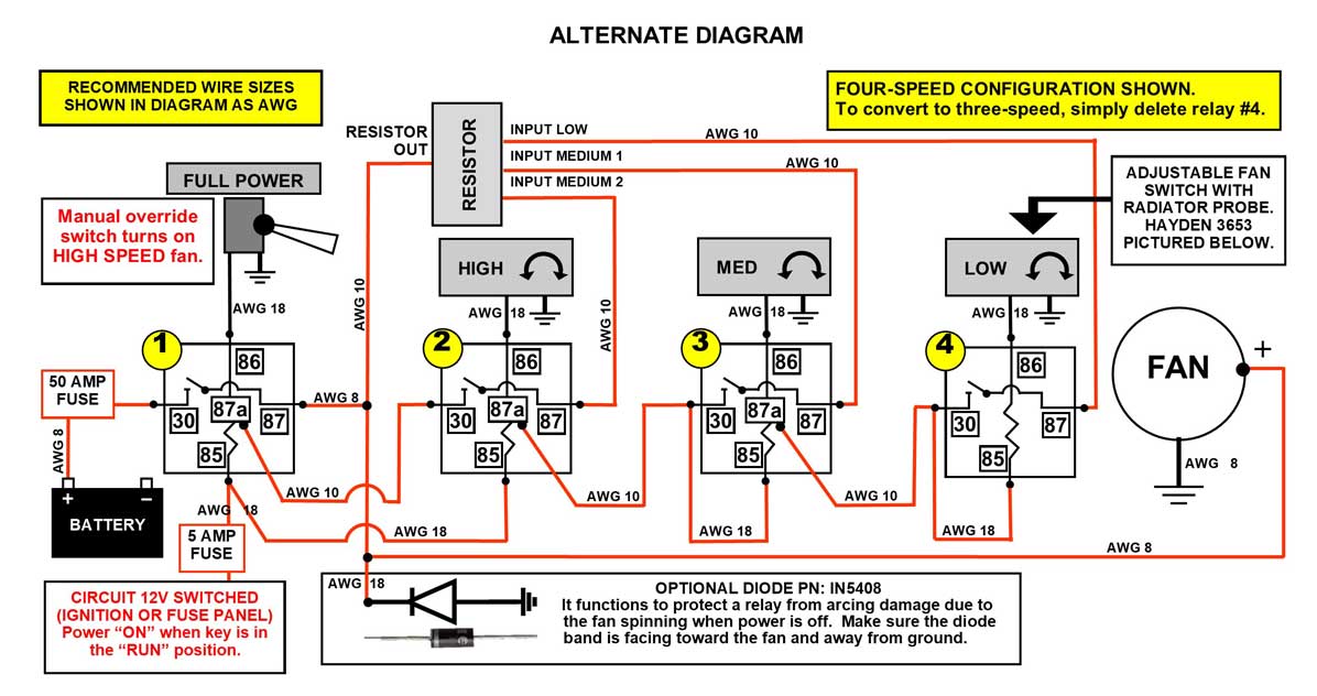 |
When your temperature climbs a little higher, the SECOND sensor will activate the next relay (Relay 3), automatically cutting power from the lower speed relay (Relay 4). This way only ONE CIRCUIT will be powering the fan at a time. This
successive function works for each relay to
increase fan speed as temperatures rise.
|
The amperage capacity for the high speed relay (Relay 1) will depend on the fan you use. Most 15 inch or smaller fans (such as those found in Volvo 960, 850, S80) can get by with a 40A relay for the high speed (however I suggest 50A). A larger fan, such as the 17-18 inch Ford Taurus/T-Bird/Lincoln Mark VIII fans, should use a 70 or 80A relay. These big fans can pull 35-40 amps continuously at full power, so power and ground cables for these fans should be fat, such as 8 gauge (AWG) or fatter. I'm using 8 gauge. |
|
 The fat cables I'm using for my project are
high-flex fine strand type. Cables in 8
gauge and larger can usually be found sold as
welding cable. I found them
sold in reasonably short lengths on Amazon so
you don't need to buy them in large spools.
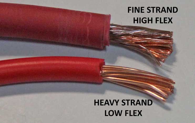
Fine strand cable has much finer strands than
common automotive cable. I'm willing to pay a
little extra because I've grown tired of
dealing with stiff, large strand cable that's
hard to form tight bends and then breaks easier after years of long-term
vibration. The fat cables I'm using for my project are
high-flex fine strand type. Cables in 8
gauge and larger can usually be found sold as
welding cable. I found them
sold in reasonably short lengths on Amazon so
you don't need to buy them in large spools.
Fine strand cable has much finer strands than
common automotive cable. I'm willing to pay a
little extra because I've grown tired of
dealing with stiff, large strand cable that's
hard to form tight bends and then breaks easier after years of long-term
vibration. Maybe you
don't think a big fat cable can snap from vibration. I found out when
a 4 gauge alternator cable snapped off
at the alternator lug from vibration after about 4
years of use, stranding me on a long
trip.
|
If you pay close attention, you'll find I used larger cables than required. That's ok in my book. Just don't use smaller than minimum. |
|
 |
The 12V switched wire at terminal 85 gets connected to the power wire that activates your AC compressor. NOTE: Or if you have an '84 to '89 Volvo 240 you may use the AC power 'ON' wire, which is the Red/White wire going to the AC microswitch (attached to the AC knob switch in the center dash). 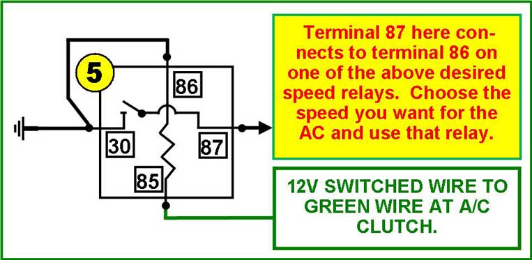
|
 Mini
ISO
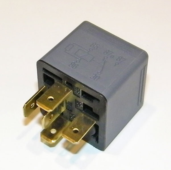
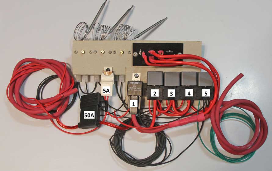
Relays used for this project: Mini
ISO
Relays used for this project:1. Full Power 100%: SPDT rated at 80 amps. 2. High: SPDT rated at 40 amps. 3. Medium: SPDT rated at 40 amps. 4. Low: SPDT or SPST rated at 40 amps. 5. AC: SPDT or SPST rated at 15 to 40 amps. |
||
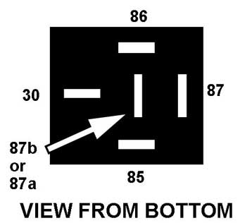 |
Mini ISO Relay
Connections (View from bottom of relay or
bottom of connector plug) SPST (Single Pole, Single Throw): This type relay will have an 87b center pole. SPDT (Single Pole, Double Throw): This type relay will have an 87a center pole. Also known as a changeover relay. RELAY PINOUTS: 30: Constant 12V (battery), unswitched 85: Signal, 12V switched (fuse panel) 86: Ground (completes coil circuit to close connection) 87: Consumer 12V (to fan or other device to be powered) 87b: Extra consumer (same circuit as 87) 87a: Opposite of 87 (SPDT changeover relay only) |
|
Single Pole, Double Throw (SPDT): If you have a relay with an 87a pin in the middle, it's an SPDT relay, also called a "changeover" relay. In a changeover relay, the 87a pin will be “HOT” anytime the 87 pin is "OFF," so long as the relay is connected to power. So when 87 is "OFF", 87a will be "ON". When 87 turns "ON", 87a will turn "OFF". |
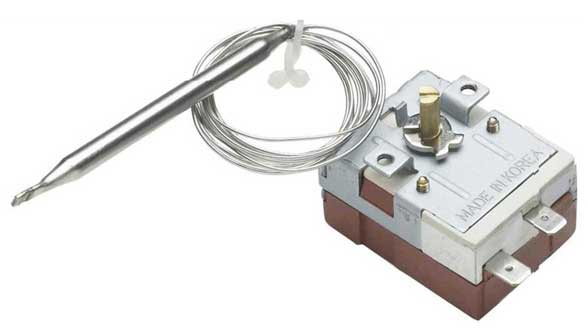
The Hayden 3653 adjustable temperature probe sensor pictured here can be purchased from places like Amazon or Summit Racing for about $20 each. It's only rated at 16 amps, so it should not be used directly to power a fan. This mechanical sensor may be used to trigger a 12V circuit or a ground circuit, either one. For my project I chose to have it complete ground circuits. The male terminals on the side are typical .250 inch (6.3 mm). According to Hayden, the temperature range is 32°F to 248°F (0°C to 120°C). Turning the trim pot CLOCKWISE increases the temperature set point; COUNTER-CLOCKWISE decreases it. The kit comes with a mounting bracket, some screws, some .250 inch insulated terminals, some wire and some mounting parts for the radiator probe. I've noticed at least one high-tech fan controller company ridiculing anyone using one of these in a car. The thing is, it's SIMPLE and SIMPLE THINGS FAIL MUCH LESS OFTEN in my experience. Why do I call it simple? Because it's MECHANICAL, not electronic. In a world where so damned many complicated high-tech fan controllers don't have such a good track record, I wouldn't spout off too much. |
|
|
|
||
|
|
||
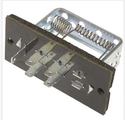
| This resistor board offers four speeds to choose from. I am only using three of them (plus I added a full power relay for full speed). I measured the resistance values for each circuit on this board and included those below. 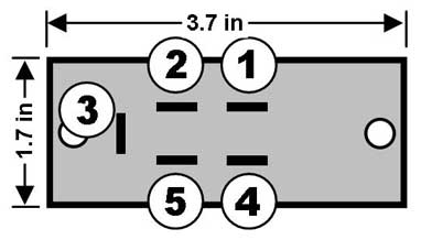
|
||
|
|
||
|
I've been told the resistor coils
can theoretically get hot when this board is
in use.
So maybe it would be best to place this thing where your fingers won't be tempted to touch it. I mounted mine in the lower left of the fan shroud. I later began taking IR temp readings from this resistor board when the fan was running and I found it to be not much higher than the shroud or radiator ambient temperature. 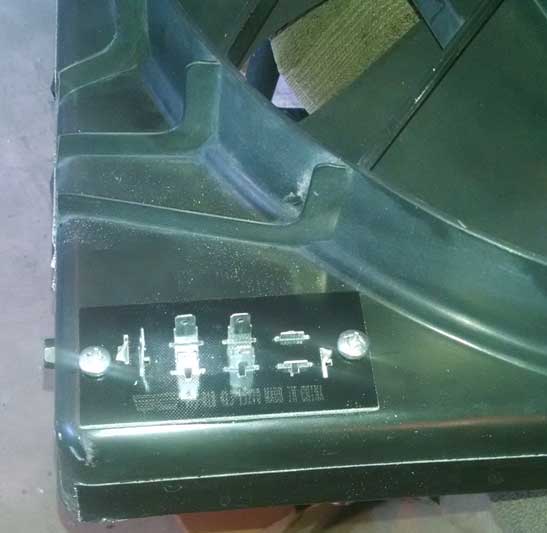
To
those of you who cried out that this resistor
board would MELT, sorry. DIDN'T HAPPEN.
|
|
||||||||||||||||||||||
|
|
||||||||||||||||||||||
Lincoln Mark VIII Fan Speed/Current Testing (using static 12.7v battery voltage with engine off) Dorman 973-018 4-speed resistor pinout shown below. |
||||||||||||||||||||||
My first surprise was seeing how the resistor HIGH circuit (through Relay 2) produced a number so much lower than 100%. That 77% figure turned out to not be a disappointment, since it offered an opportunity for an extra speed choice below 100%. Using fan speed figures like this, you can decide which circuits or resistors you want to use for the fan speeds you like. That low 26% speed might sound ok on paper for a low speed, but once I saw how slow that actually ran the fan, I felt differently. It was too slow for my use. You can see in my diagram up near the top of the page I had originally listed this 26% for my LOW speed. The reality was that it was too low on my car with an intercooler and AC condenser blocking the radiator. So I decided to use the 36% speed as my LOW speed instead. This provided a really nice SOFT START too. That 26% low speed might work for a different car without an intercooler and AC condenser blocking the radiator. Every car is different. |
||||||||||||||||||||||
Using running battery voltage (voltage readings below). Since the 26% low speed was not used in the final version, it was not measured here below. I was using a 188 degree Fahrenheit coolant thermostat in the engine and the 36% speed seemed to do very well to keep things nice and cool at idle on a warm 85 degree day. If the climate is warmer, then the medium 55% speed may come on occasionally. Keep in mind that every car is different. My car has a very large aftermarket AC condenser (with dual fans) and an intercooler in front of the radiator. Those items obstruct the flow of air to the radiator a lot when compared to car without those items.
|
||||||||||||||||||
FINAL
SPEED
SETTINGS CHOSEN FOR THIS PROJECT
|
||||||||||||||||||
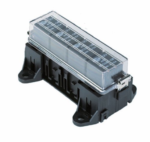 Hella H84988001 Four
Relay Sealed Box. Available on-line for
about $40 to $50. Pricey, yes! If you're
concerned about moisture messing with relays or
maybe you just want them to look nicer, this may
be a solution. Keep
in mind this box is NOT waterproof.
There is an o-ring sealed lid, but the bottom is
not sealed at all. NOTE: The
high-current 80A (full-power) relay will NOT fit
in this box, since it uses a couple .375 inch
terminals instead of all small .250 inch terminals
like standard relays. This
box holds only standard relays. The 90
degree mounting ears are removeable and supposedly
you can connect two or more of these boxes
together side by side. Hella H84988001 Four
Relay Sealed Box. Available on-line for
about $40 to $50. Pricey, yes! If you're
concerned about moisture messing with relays or
maybe you just want them to look nicer, this may
be a solution. Keep
in mind this box is NOT waterproof.
There is an o-ring sealed lid, but the bottom is
not sealed at all. NOTE: The
high-current 80A (full-power) relay will NOT fit
in this box, since it uses a couple .375 inch
terminals instead of all small .250 inch terminals
like standard relays. This
box holds only standard relays. The 90
degree mounting ears are removeable and supposedly
you can connect two or more of these boxes
together side by side.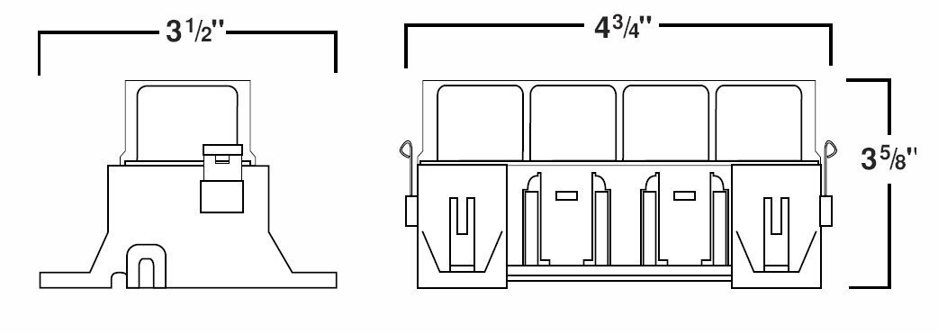 |
|
|
|
|
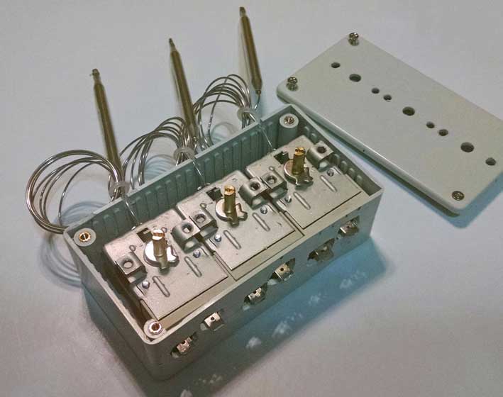 I found an ABS
project box to fit the three Hayden sensors and to
help make this installation look nicer. There
are a lot of sizes out there for boxes in a couple
colors, including black. This box is 4.7 inches long x 2.6
inches wide x 1.4 inches tall O.D. (found
on Amazon). I had to do some grinding on the
inside to make everything fit inside. A larger box
would have been easier, but I wanted it as compact
as possible. Cost was about $6.00. The box was
painted black before completion. I found an ABS
project box to fit the three Hayden sensors and to
help make this installation look nicer. There
are a lot of sizes out there for boxes in a couple
colors, including black. This box is 4.7 inches long x 2.6
inches wide x 1.4 inches tall O.D. (found
on Amazon). I had to do some grinding on the
inside to make everything fit inside. A larger box
would have been easier, but I wanted it as compact
as possible. Cost was about $6.00. The box was
painted black before completion.Since doing this I found a better sized box that I probably would have chosen instead: >>> https://www.polycase.com/lp-55p. Its dimensions are 5 x 3.5 x 1.5 inches (127 x 88.9 x 38.1 mm). It would likely have been a better fit and I think with little or no cutting and carving. |
|
|
|
|
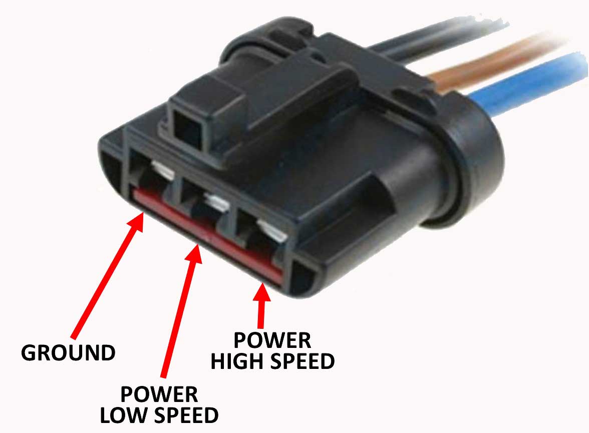 <<<
Ford Fan
Motor Connector. Fits a variety of
Ford/Lincoln/Mercury fans, including the Mark VIII
fan I have. A google search will find them in a
few places. I have only found them available with
12 gauge wire pigtails. In my opinion that's
a bit small for such a fan. I 'm using 8
gauge welding cable. <<<
Ford Fan
Motor Connector. Fits a variety of
Ford/Lincoln/Mercury fans, including the Mark VIII
fan I have. A google search will find them in a
few places. I have only found them available with
12 gauge wire pigtails. In my opinion that's
a bit small for such a fan. I 'm using 8
gauge welding cable. |
|
|
|
|
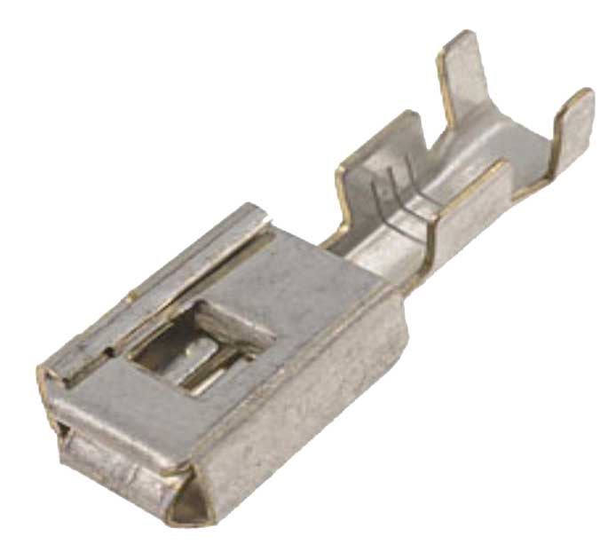 <<< Dorman
Conduct-Tite Terminal, AKA: Ford
Standard Block Technician Terminal. This is the
type of terminal that goes into the Ford fan motor
connector. Dorman offers PN 85367 which fits 14-16
gauge wire and is available on line. <<< Dorman
Conduct-Tite Terminal, AKA: Ford
Standard Block Technician Terminal. This is the
type of terminal that goes into the Ford fan motor
connector. Dorman offers PN 85367 which fits 14-16
gauge wire and is available on line. A 10-12 gauge version would be more appropriate, however at this writing it has NOT been found. |
|
|
|
|
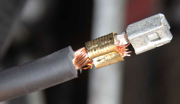 <<< So I improvised and
successfully used the 14-16 gauge terminals since
I couldn't find larger ones. I added one of my large
terminal overcrimps to make a solid crimp over
the 8 gauge cable I used.
Inserting this into the back of the Ford
connector housing can be a little tight. I
opened up the holes on the back of the connector
to accommodate this fat cable. If
necessary, a little trimming of the inside of
the housing with a hobby knife will help it go
in and click. Mine went in and clicked in
place without an issue. <<< So I improvised and
successfully used the 14-16 gauge terminals since
I couldn't find larger ones. I added one of my large
terminal overcrimps to make a solid crimp over
the 8 gauge cable I used.
Inserting this into the back of the Ford
connector housing can be a little tight. I
opened up the holes on the back of the connector
to accommodate this fat cable. If
necessary, a little trimming of the inside of
the housing with a hobby knife will help it go
in and click. Mine went in and clicked in
place without an issue. |
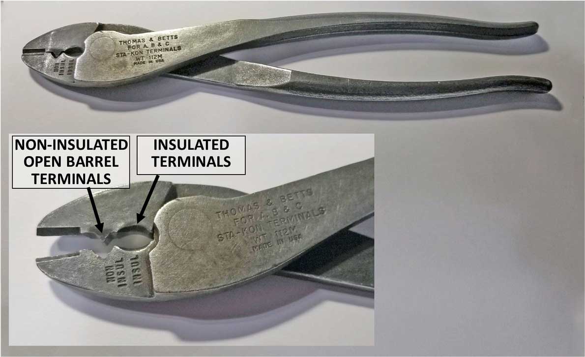 <<<
PROPER
CRIMP tools are important. Try not to use too cheap a
crimper or the wrong type for the terminal
you're using. Buy yourself something at
least as good as this one.
<<<
PROPER
CRIMP tools are important. Try not to use too cheap a
crimper or the wrong type for the terminal
you're using. Buy yourself something at
least as good as this one. For those of you who are curious about what crimper I use, this is it for 90% of my crimps for non-insulated (and many insulated) open barrel terminals. Thomas & Betts model WT 112M. It runs about $45. I've had this one for 20 plus years. With some
practice, this simple tool can create nice
crimps just like a fancy tool.
|
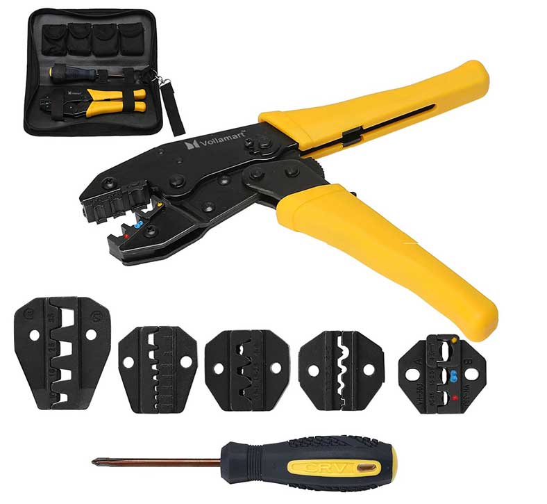 <<<
For a tool
that's a bit more fancy, look for a ratcheting
crimper that will do open barrel F type terminals.
You can spend a lot of money on one of these
tools, but it you hunt carefully, you can find
something like this one, which is only $31 for all
that stuff. Although sometimes you get what
you pay for. The crimp type normally used for open
barrel terminals I offer in my page is the die set
in the center. The others might come in
handy, so they would be a bonus. I don't own
this one. My fancy racheting crimper was
about $80 ten plus years ago from Summit Racing.
This one is cheap and might be worth the cost, or
it might explode. You can never really tell until
it's in your hands.
<<<
For a tool
that's a bit more fancy, look for a ratcheting
crimper that will do open barrel F type terminals.
You can spend a lot of money on one of these
tools, but it you hunt carefully, you can find
something like this one, which is only $31 for all
that stuff. Although sometimes you get what
you pay for. The crimp type normally used for open
barrel terminals I offer in my page is the die set
in the center. The others might come in
handy, so they would be a bonus. I don't own
this one. My fancy racheting crimper was
about $80 ten plus years ago from Summit Racing.
This one is cheap and might be worth the cost, or
it might explode. You can never really tell until
it's in your hands. HERE: https://www.amazon.com/dp/B01CVH8JNO?psc=1 |
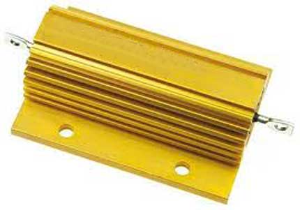 <<< This is an aluminum
Chassis Mount Resistor. It
is NOT something I have tested or used in this
project.
The reason this info is here is because It has been
suggested for durability, particularly in corrosive
or wetter environments. Some of you might want to
consider a different style resistor instead of the
Dorman resistor board I used. Most of the
suggestions people have sent have been pointing to
ceramic automotive resistors, such as those used for
ignition, AC and cooling fans older cars. The
problem I encountered is that there are very
few choices for varied resistance values in ceramic, so it may take a
lot of trial and error to get that working
well. <<< This is an aluminum
Chassis Mount Resistor. It
is NOT something I have tested or used in this
project.
The reason this info is here is because It has been
suggested for durability, particularly in corrosive
or wetter environments. Some of you might want to
consider a different style resistor instead of the
Dorman resistor board I used. Most of the
suggestions people have sent have been pointing to
ceramic automotive resistors, such as those used for
ignition, AC and cooling fans older cars. The
problem I encountered is that there are very
few choices for varied resistance values in ceramic, so it may take a
lot of trial and error to get that working
well. So I began looking closer at these Chassis Mount Resistors. The dimensions for the models listed below are 65 x 47 x 26 mm (about 2.5 x 1.9 x 1.25 inches). They run about $10 each and they're rated for WET CONDITIONS. Most ceramic resistors have only a 30-40 watt capacity. The chassis mount types I have listed below all have a 100 watt capacity. You would need three of them to come close to duplicating the three speeds I have achieved with the Dorman resistor board, however I have not tested any of these yet to see what speeds they will actually generate. Since the four ohm values I found in the Dorman resistor board were 0.3, 0.8, 1.4 and 3.1 (I'm not using 3.1 ohms), you can try some that are reasonably close to that, such as 0.22, 1, 1.5 and 3 ohms.
A source I found for these is DigiKey
Electronics: http://www.digikey.com/product-search/en?keywords=resistor.
If
you
incorporate something like this in your build,
please email me. I would like to know how your
project goes. CONTACT ME.
|
|
||||||||||||||||||
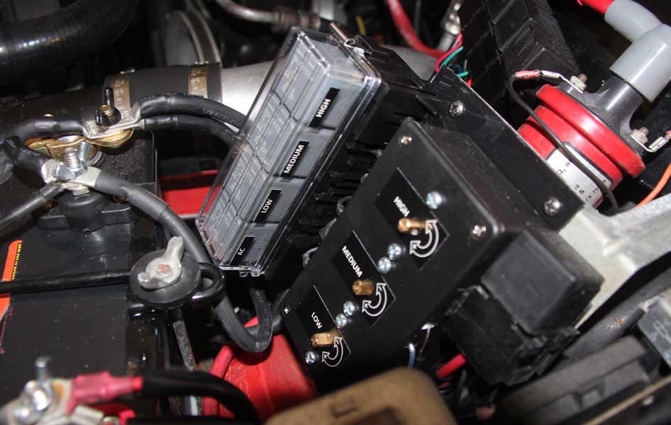 <<< Here's the full
setup installed in my 240. As you can see I opted
for the fancy Hella relay box. Those four
relays in the box are for AC, Low, Medium and High
speed. <<< Here's the full
setup installed in my 240. As you can see I opted
for the fancy Hella relay box. Those four
relays in the box are for AC, Low, Medium and High
speed. |
||||||||||||||||||
|
|
||||||||||||||||||
| <<< Another angle.
That relay on the left side of the Hella box is the
80A full power relay. It's triggered by the override
switch on my dash. Hopefully it won't be needed, but
it comforts me to have it just in case. This setup has been used in 105 degree plus Texas climate it works exceptionally well. The 77% speed I chose for the AC works very well also. |
||||||||||||||||||
|
|
||||||||||||||||||
 <<< Here's another view of the Dorman resistor board mounted in the lower left corner of the fan shroud. That is 10 gauge high-flex wire. The terminals are .312 inch (headlight terminals), since I found they actually fit better and provide more contact area than the .250 inch terminals that are normally used on there. There are people who thought this resistor board would melt. Two years later and all is working perfectly. So there, stupid doubters. |
||||||||||||||||||
|
|
||||||||||||||||||
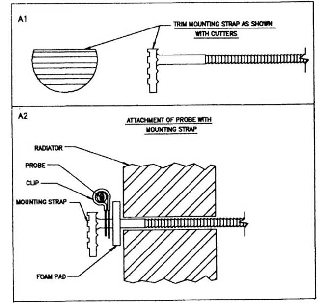 BAD
RECOMMENDATIONS BAD
RECOMMENDATIONS<<< This is worth mentioning if you decide to used a Hayden 3653 temp sensor. It concerns mounting the radiator fin probes in or on the radiator. This image is from their instructions. They supply the shown probe mounting parts and tell you to mount the probe in a supplied metal/rubber mounting strap that is then isolated from the radiator by a foam pad. THIS IS A REALLY BAD IDEA. What this does is delay radiator temps from quickly transmitting to the probe. The delay with mounting it this way is substantial. It has slightly less of an effect when hot air from the radiator is blowing through and past the probe, but there will be signiificant delay when warming up the engine (if the fan is not blowing) or if the car is not moving and air is not flowing yet. The delay will be such that the radiator will heat up PAST the setting you want for the fan to come on, so then your fan comes on late. Then it will DELAY the fan from shutting down as the radiator temps drop off, causing wide swings of the fan on/off cycle. You'll curse Hayden because you wont be able to accurately dial in your settings. It's just bad. Don't follow those instructions. |
||||||||||||||||||
|
|
||||||||||||||||||
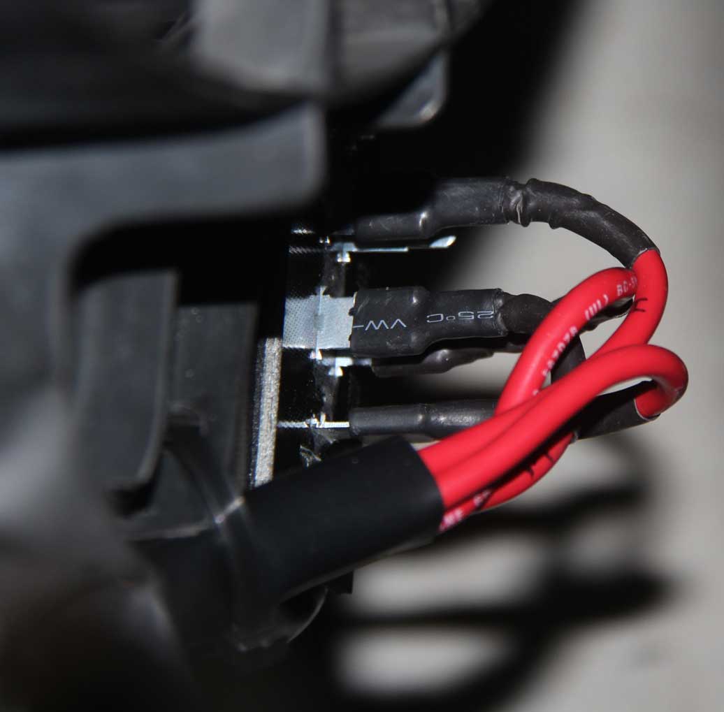
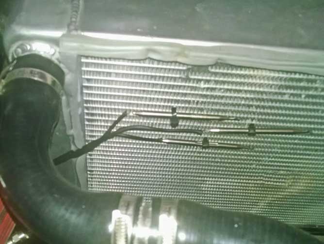 <<< DO
THIS INSTEAD: The probes that come with these
units are a bit fat and would not slip into my
radiator fins without a lot of force. This may
be why Hayden wrote those instructions that
way. I didn't want to risk damage to my
expensive aluminum radiator by bending things and
forcing the probes in, so I mounted the probes
tightly against the radiator fins as shown in this
photo using thin zip-ties. While it might be hard to
tell in this photo, the
full length of each probe is very snug against the
radiator fins and they have good, solid contact. Sensor activation
with this method is quick and accurate. Faith
in Hayden has been restored. <<< DO
THIS INSTEAD: The probes that come with these
units are a bit fat and would not slip into my
radiator fins without a lot of force. This may
be why Hayden wrote those instructions that
way. I didn't want to risk damage to my
expensive aluminum radiator by bending things and
forcing the probes in, so I mounted the probes
tightly against the radiator fins as shown in this
photo using thin zip-ties. While it might be hard to
tell in this photo, the
full length of each probe is very snug against the
radiator fins and they have good, solid contact. Sensor activation
with this method is quick and accurate. Faith
in Hayden has been restored. |
||||||||||||||||||
|
|
||||||||||||||||||
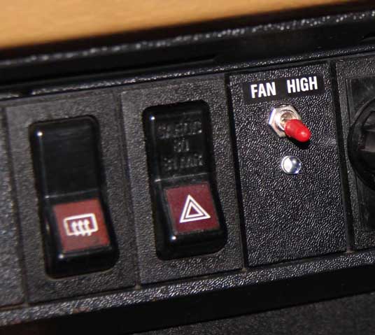 <<< Here's the override switch I placed on my dash. The small LED bulb below the switch illuminates green when the fan is on. |
||||||||||||||||||
|
|
||||||||||||||||||
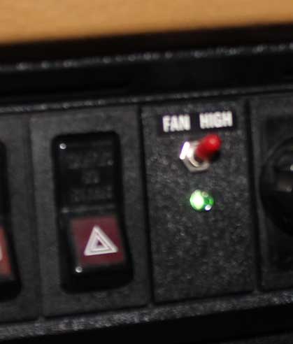 <<< The LED turned out to be too bright with full 12 volts, so I added a 220k ohm resistor to the power wire. Now it seems just right with a low green glow. |
||||||||||||||||||
|
||||||||||||||||||
| Your comments are welcome. CONTACT ME |
Relay - Picker High Current 80A
relay (SPDT). Qty
1.
Available here:
https://www.prancingmoose.com/volvorelays.html#highcurrentrelay Relay - Tyco gray “101” 40A
relay (SPDT). Qty:
4.
Available
here: https://www.prancingmoose.com/volvorelays.html#1259926-101gray Relay plug socket,
interlocking, 5-pole. Qty:
4.
Available here:
https://www.prancingmoose.com/volvorelays.html#relayplug Optional
- Hella H84988001 Sealed Box for four relays. Qty: 1 Relay high-current plug socket,
5-pole. Qty:
1.
Available here:
https://www.prancingmoose.com/volvorelays.html#highcurrentplug
Fuse holder (mini fuse) with 5A
fuse (18 gauge wire). Qty: 1 Fuse holder (maxi fuse) with
50A fuse (8 gauge wire). Qty: 1. Hayden 3653 adjustable temp
sensor. Qty: 3. Resistor pack -
Dorman 973-018 4-speed fan resistor. Qty: 1. Diode - PN
IN5408.
Qty:
1.
Wire - 8 gauge (high flex
welding cable recommended). Qty: about 8 feet red. Wire - 10 gauge (high flex
marine grade recommended). Qty: about 2 feet red. Wire - 16-18 gauge auto primary
wire. Red and black. Qty: about 8 feet red and
black. Heat-Shrink Tubing - Varies
sizes (maybe 3/8 to 1/2 inch) in black or red and
black. Toggle Switch -
On/Off for high speed relay override wire.
Dash mounted. Qty: 1. Crimp terminal - .375" (9.5 mm)
female, 6-10 gauge (for high-current relay). Qty:
3.
Available here:
https://www.prancingmoose.com/blackvinyl.html#.375inchterminals Crimp terminal - .312" (7.9 mm)
female straight, 10 gauge (for Dorman resistor).
Qty: 4. Available here:
https://www.prancingmoose.com/blackvinyl.html#headlightplugs Terminal Overcrimp (optional) -
Large (for Dorman resistor terminals using 10 gauge
wire). Qty: 4. Available
here: https://www.prancingmoose.com/blackvinyl.html#overcrimps Crimp terminal - .250” (6.3 mm)
female, 10-12 gauge (for relays). Qty:
7.
Available
here: https://www.prancingmoose.com/blackvinyl.html#.250inchplugs Crimp terminal - .250” (6.3 mm)
female, 14-18 gauge (for relays). Qty:
12.
Available
here: https://www.prancingmoose.com/blackvinyl.html#.250inchplugs |
|
|
||||
| davebarton.com |
prancingmoose.com |
240turbo.com |
Special Emblems |
|
| Prancing
Moose Stickers |
Volvo
Stickers |
Body/Chassis/Engine
Labels |
240 MODS and FIXES Page | |
| Other Car Brand
Stickers |
Steering
Wheel Labels |
Center Cap Labels/Overlays |
Cool Volvo
Products |
|
| Grill Labels/Overlays |
Volvo Wire
Harnesses |
Conversion Harnesses |
Harness
Parts/Connectors |
|
| Volvo Relays |
Coil Repair
Harnesses |
240 Window
Scrapers |
740/940
Window Scrapers |
|
| Adjustable Voltage
Regulators |
Horn Buttons |
240 Odometer
Repair |
740 Odometer
Repair |
|
| Volvo Gauge
Faces |
740
Turbo/Boost Faces |
240 Black Door Vinyl |
850 Odometer
Repair |
|
| ALTERNATOR Page |
240 Power Mirrors - Switches |
240 Oil Cooler Page |
240 Fuse Panel Page |
|
| Group A
Racing 242 Turbo Page |
240 Hydraulic Clutch | Fuel Pump RELAY Page |
240 Headlight RELAY Page |
|
| Used Parts & Extra Stuff for sale |
CRIMPING Page |
240 Ignition Page |
240 Headlight Page |
|
| 240 Gauge Electrical Diagrams | 240 REAR END Page | Yoshifab Catch Can Install | 240 TAILLIGHT Page | |
| Side Marker
Lights Page |
Gentex Mirror Upgrade | Yoshifab Drain Tube Install | Modified 240 Favorites | |
| SoCal Salvage Yards | Unleaded Racing Fuel | B26FT Stroker | Dave's 245 Spec Page | |
| 240 SUSPENSION Page | 240 Lowering Page |
240 Windshield Page |
240 WIPER Page | |
| 240 BRAKES Page |
240 Dash Top Gauge Pod | Cadillac 4-Note Horn Install | 240 DYNAMAT Installation | |
| 4 Speed Fan
Controller |
Electric Cooling Fan
Page |
BRUSHLESS Cooling Fan Page |
Tropical Fan
Clutches |
|
| 240 AC Page | "KOMFORT BLINKER" Upgrade | T5 Trans Conversion Page | 240 Engine Mount Page | |
| 240 VIN Page | Stepper Idle Valve Page |
Vacuum Diagrams | 240 HOOD Page | |
| 240 Exhaust Page | 242 Power Vent Window Project |
EFI Volvo Pin Function Diagrams |
Favorite Links | |
| R-Sport
Apparel |
Prancing
Moose Apparel |
Volvo Meet Photo Albums | Texas Volvo Meets and Events | |
| Ordering Instructions | Policies | PAYMENTS Page |
Mojave Road Trail Map Page |
|
| Returns | Shipping | Shopping Cart Troubleshooting | Contact Us |
|

|