|
2 4 0 T U R B O . C O M D A V E ' S V O L V O P A G E
|
||||||||||||||||||||||||||||||||||||||||||||||||||
|
2 4 0 T U R B O . C O M D A V E ' S V O L V O P A G E
|
||||||||||||||||||||||||||||||||||||||||||||||||||
| If you can help with these diagrams or have a suggestion, please email: CONTACT |
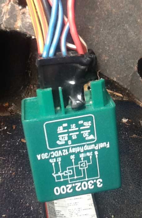
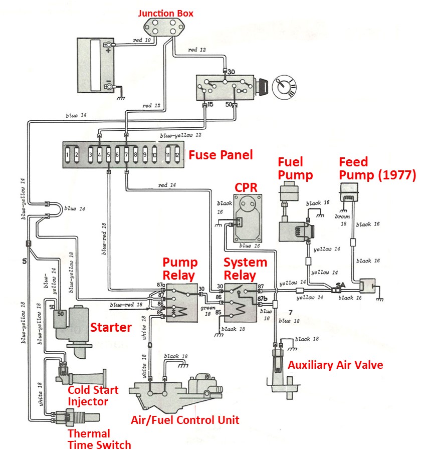
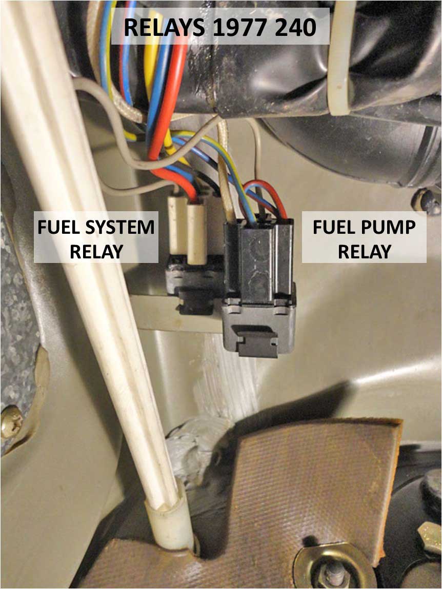
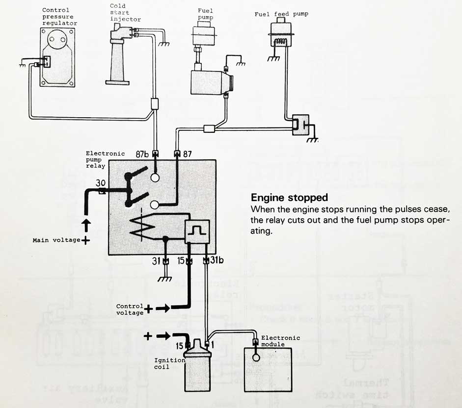
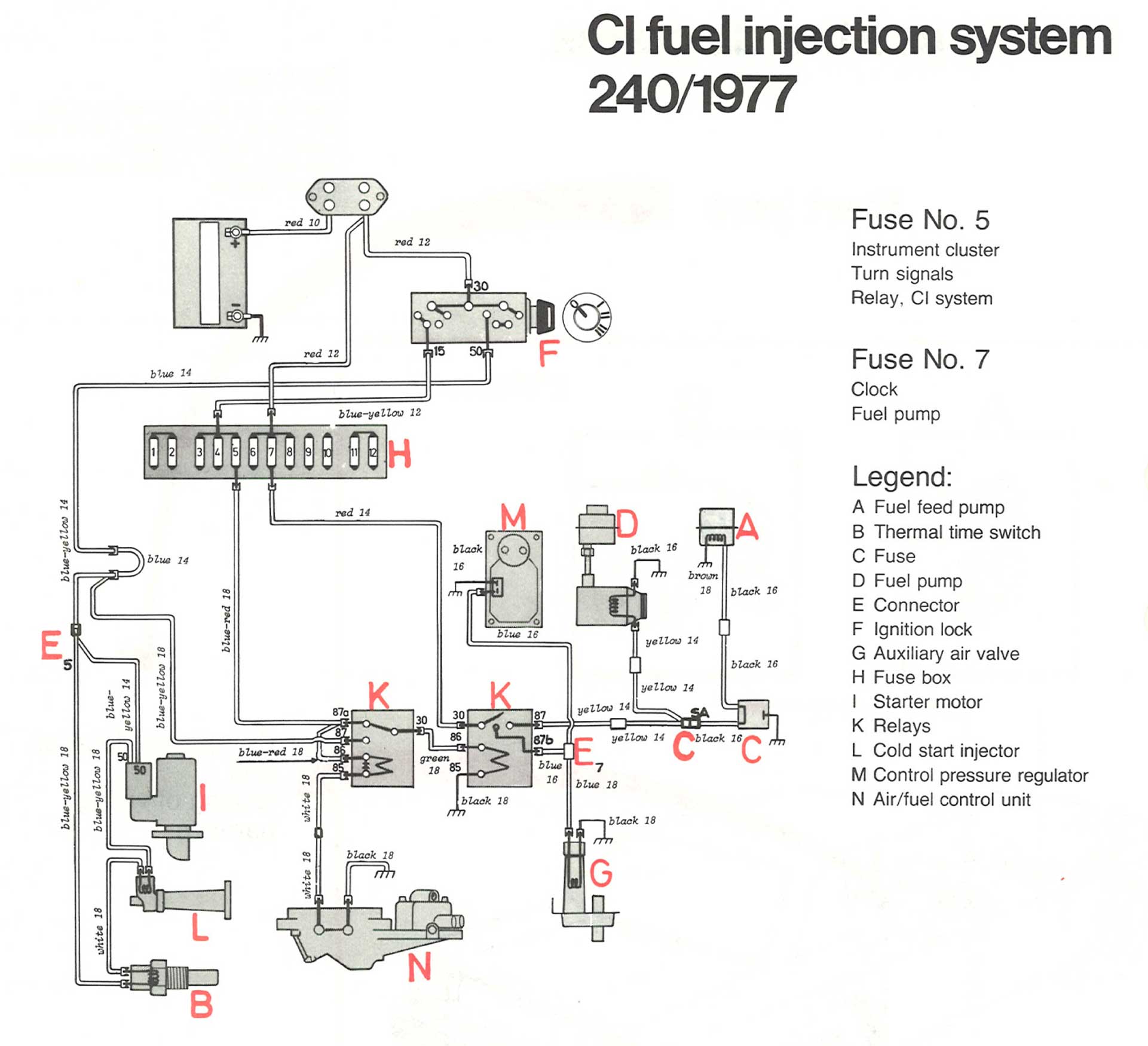
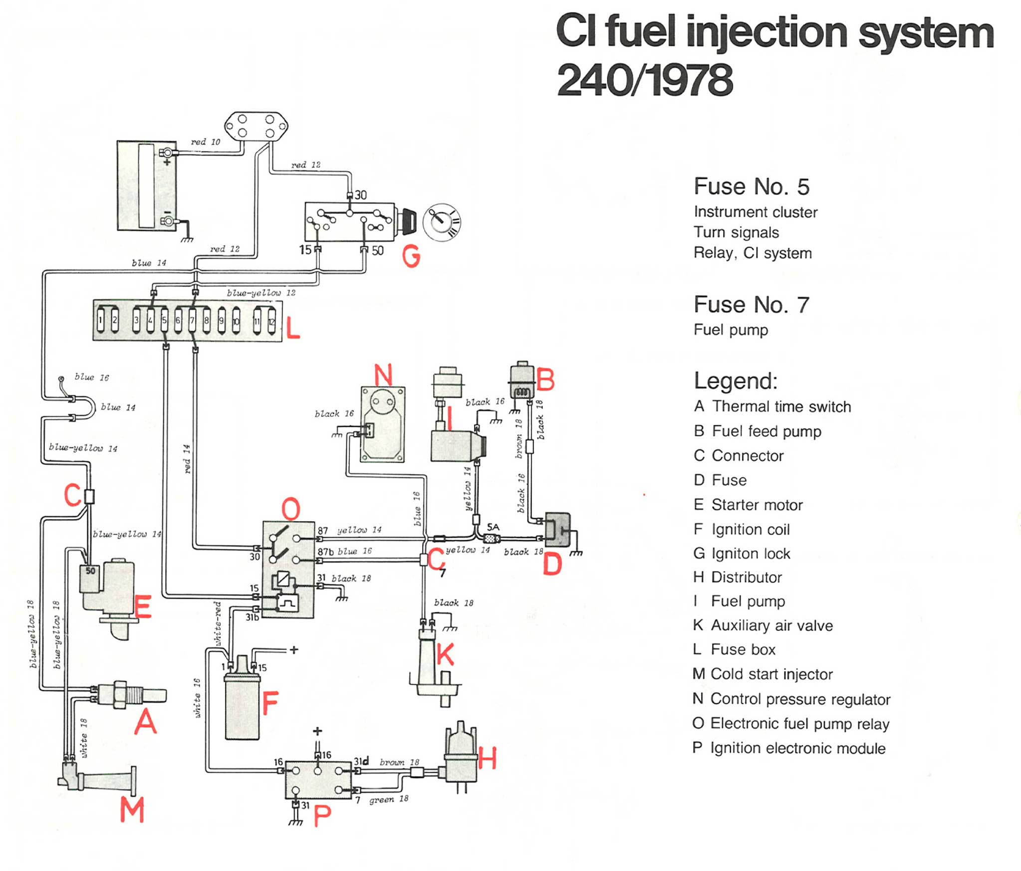
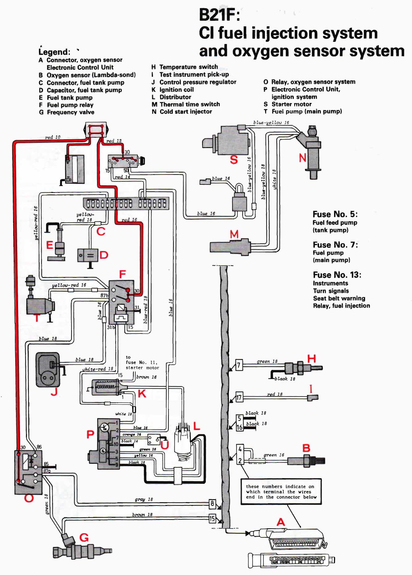
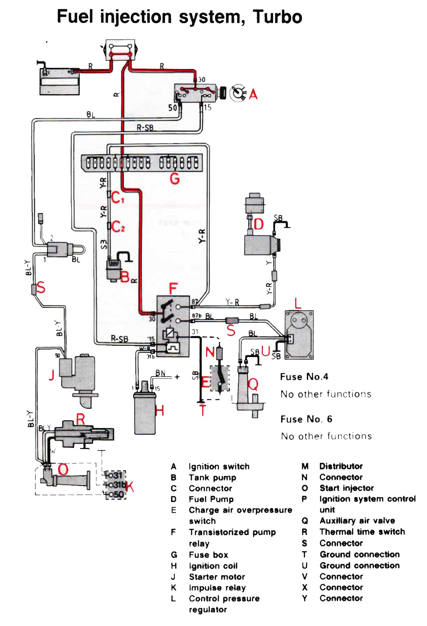
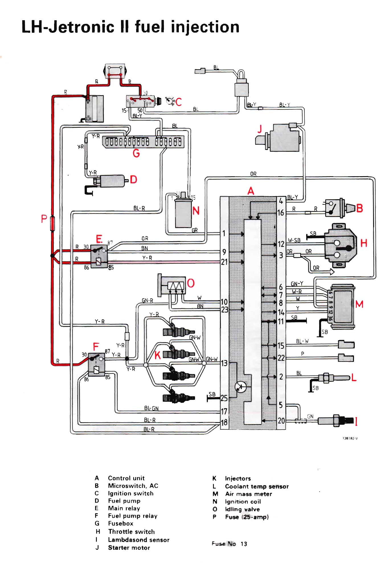
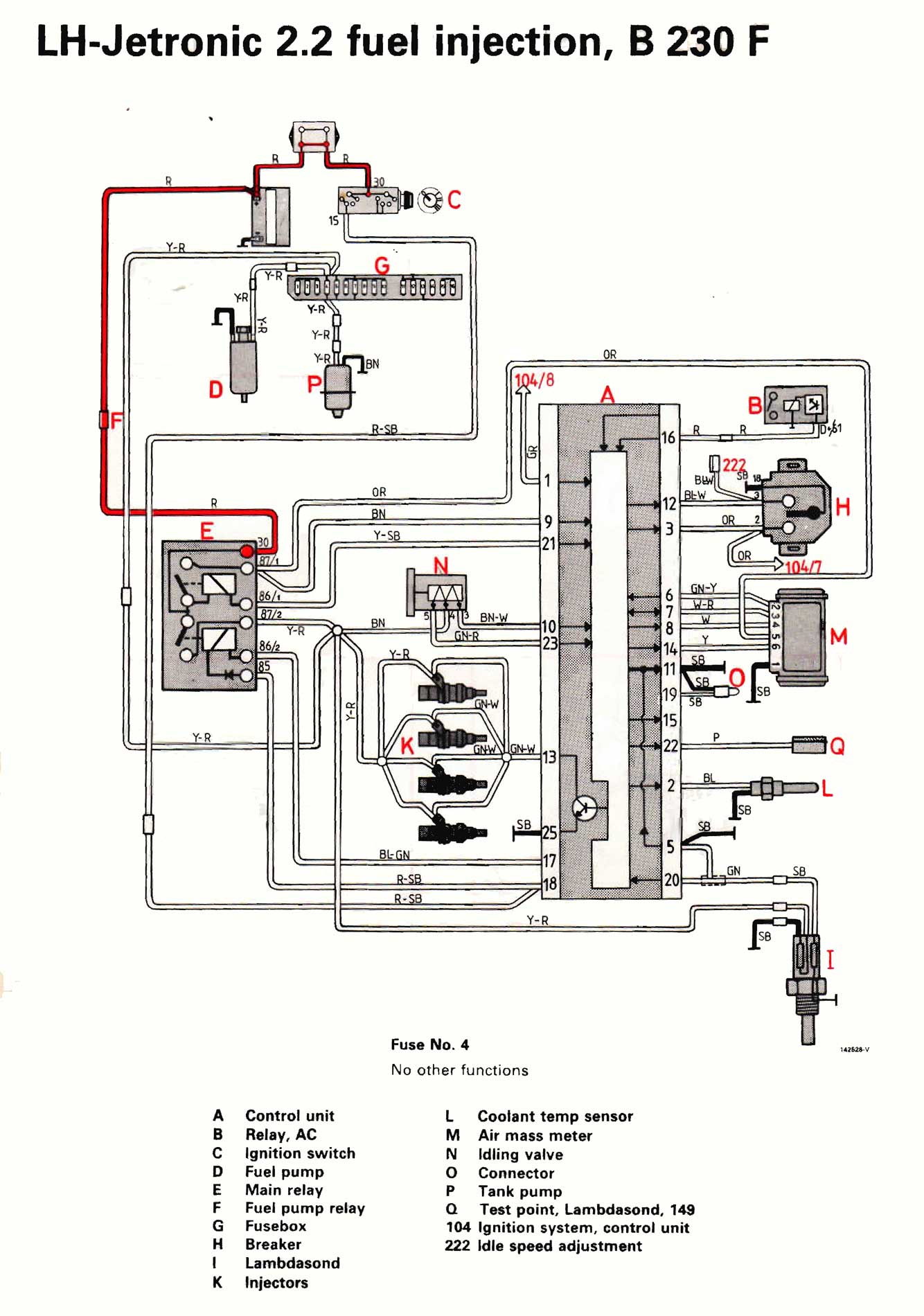
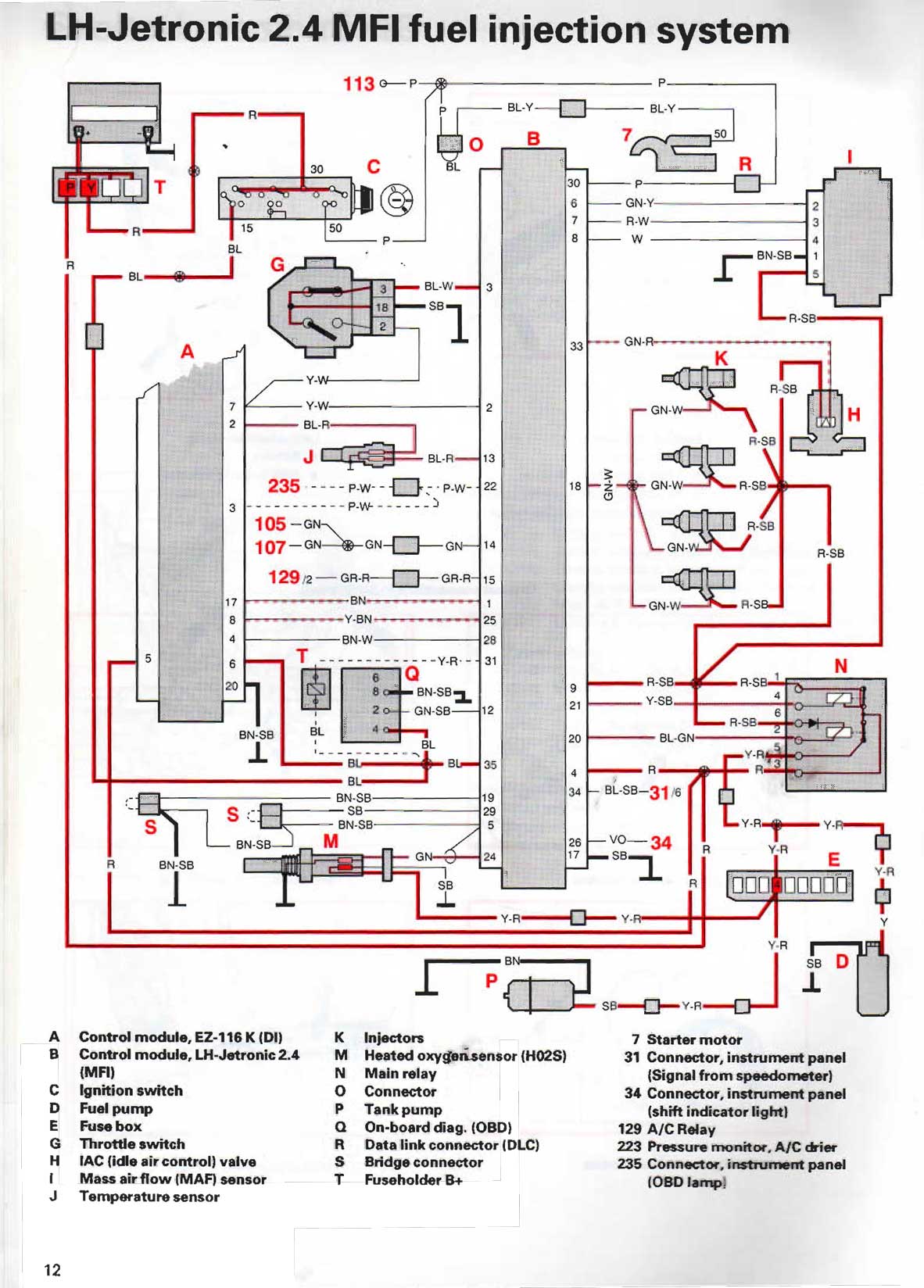
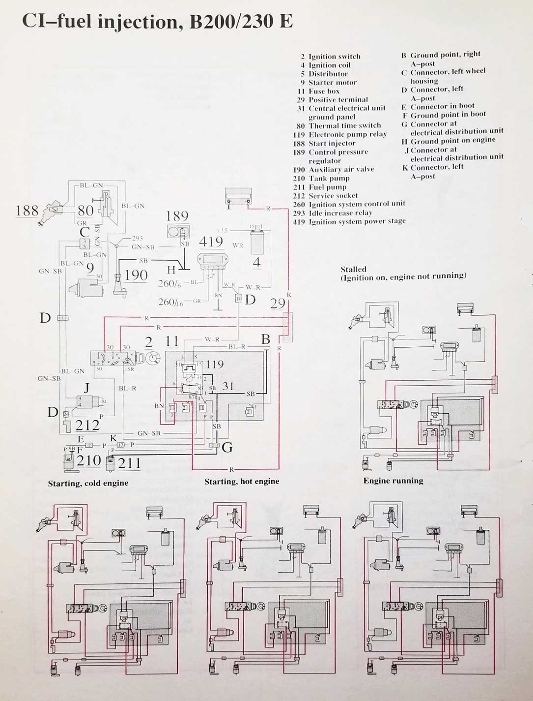
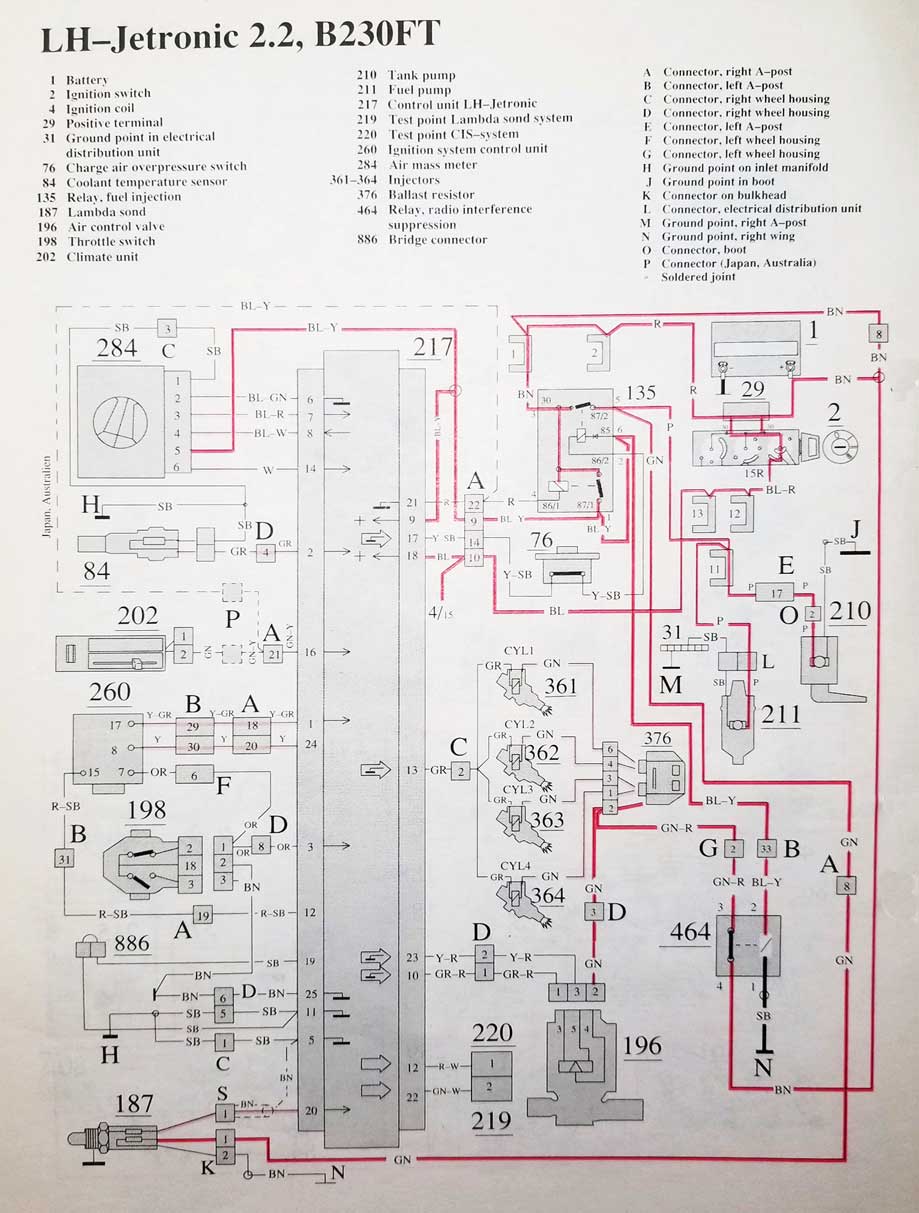
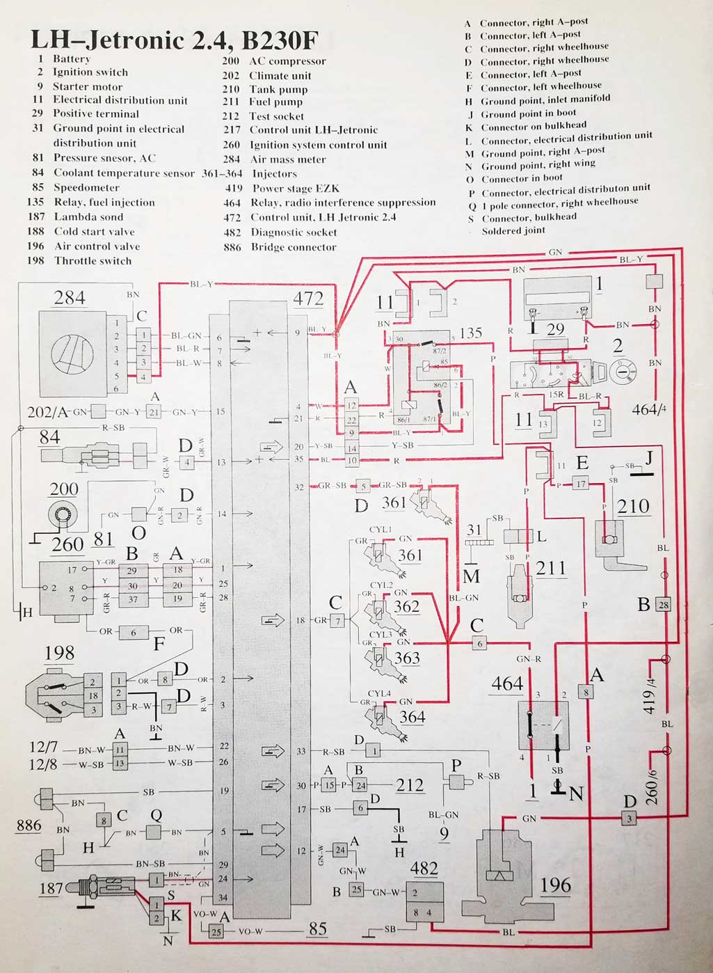
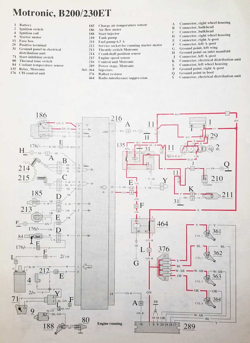
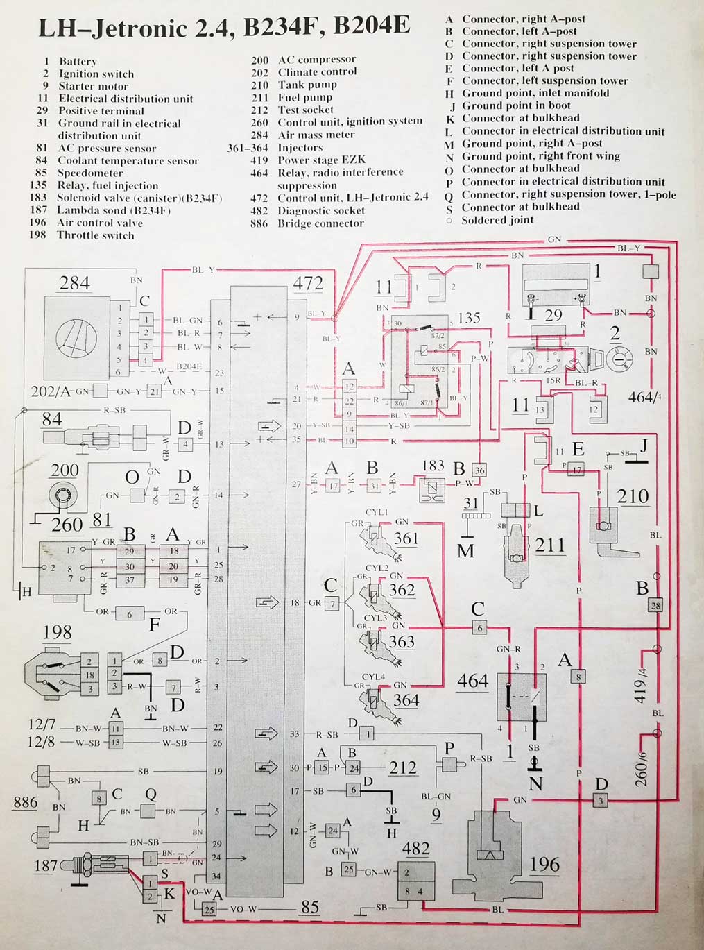
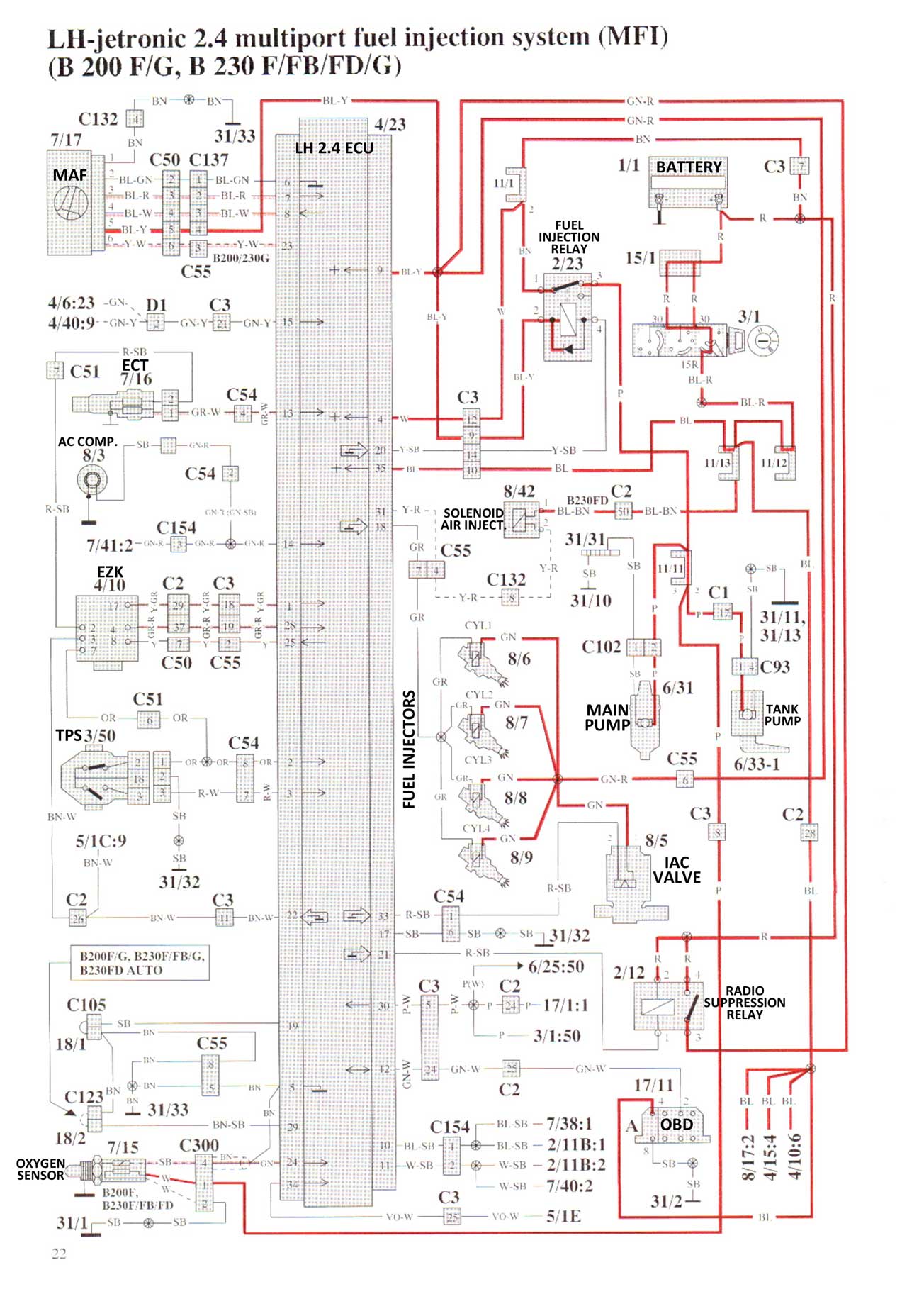
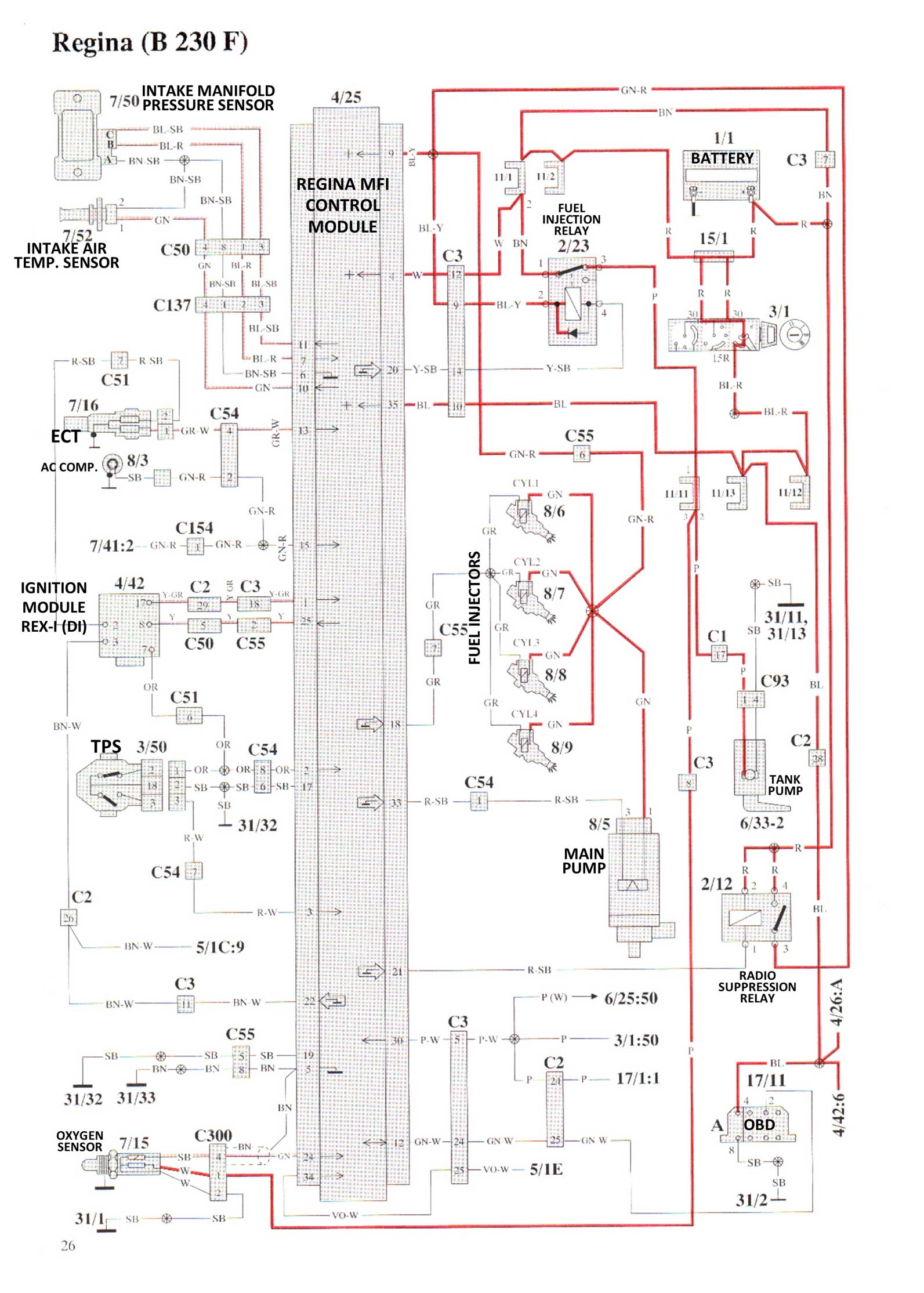
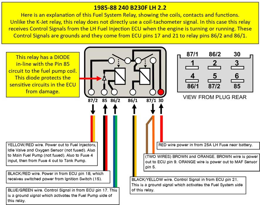
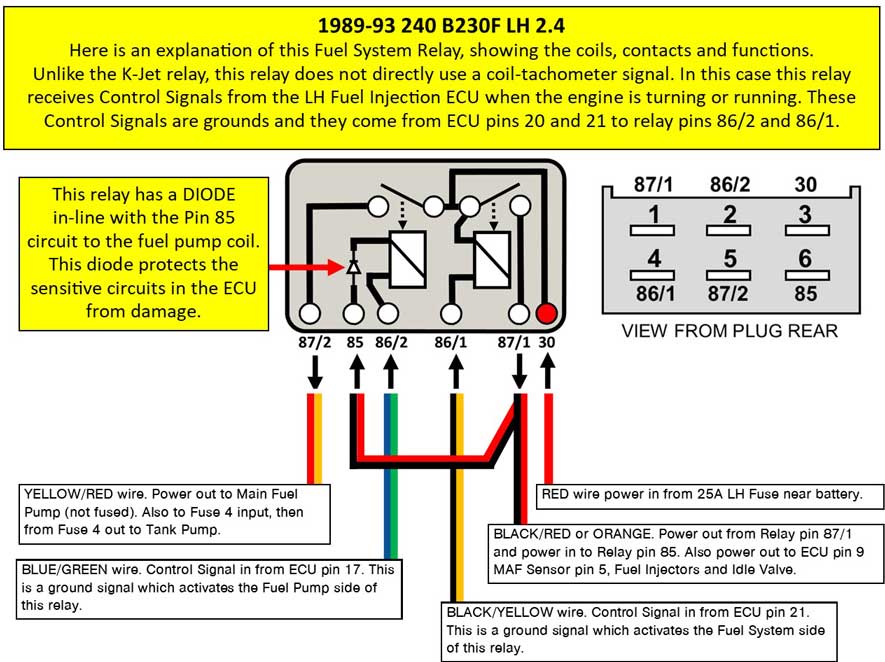
Typical 240, 740, 940 Fuel Pump Wiring Circuits 240 Fuel pump and fuel pump relay circuits can be a mystery. Here are some general diagrams showing how they were done over the years. Keep in mind that these diagrams, which were originally created by Volvo, are not always accurate. Sometimes there are small differences found on the actual cars. Sometimes it's a different wire color or sometimes a different wire path, but generally these diagrams can be useful.
https://www.prancingmoose.com/pinfunctions |
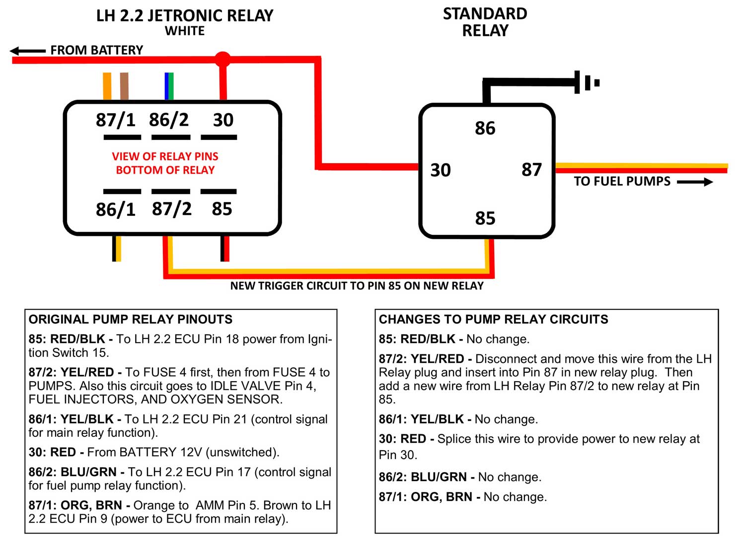
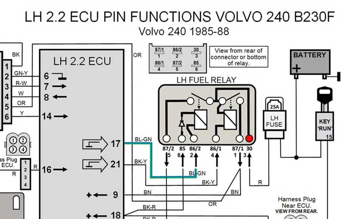
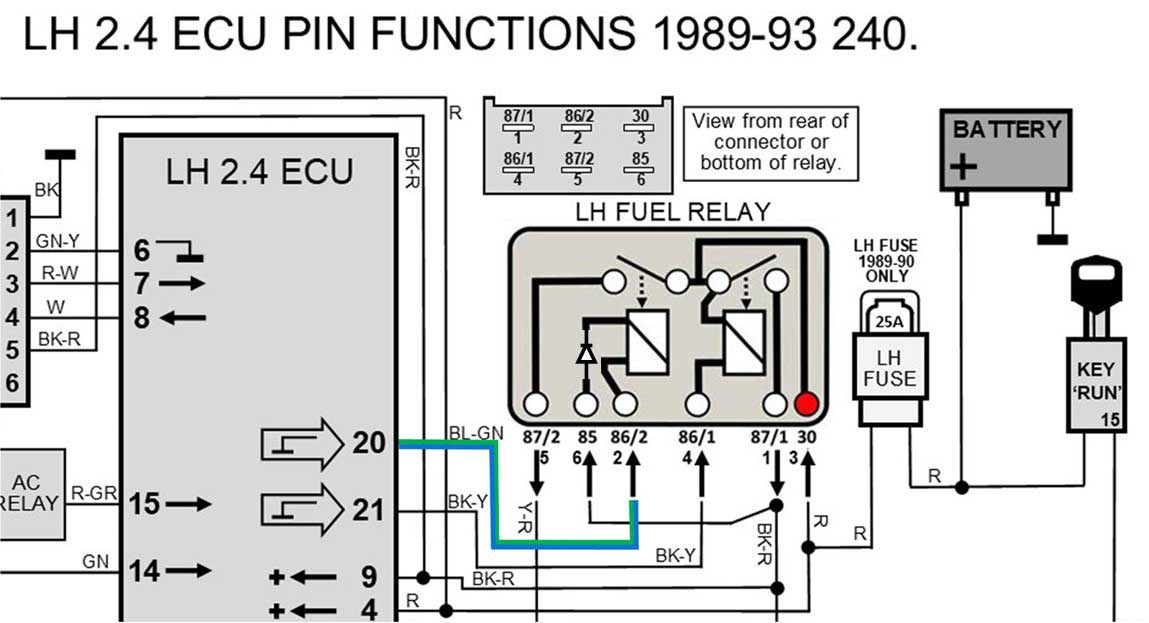
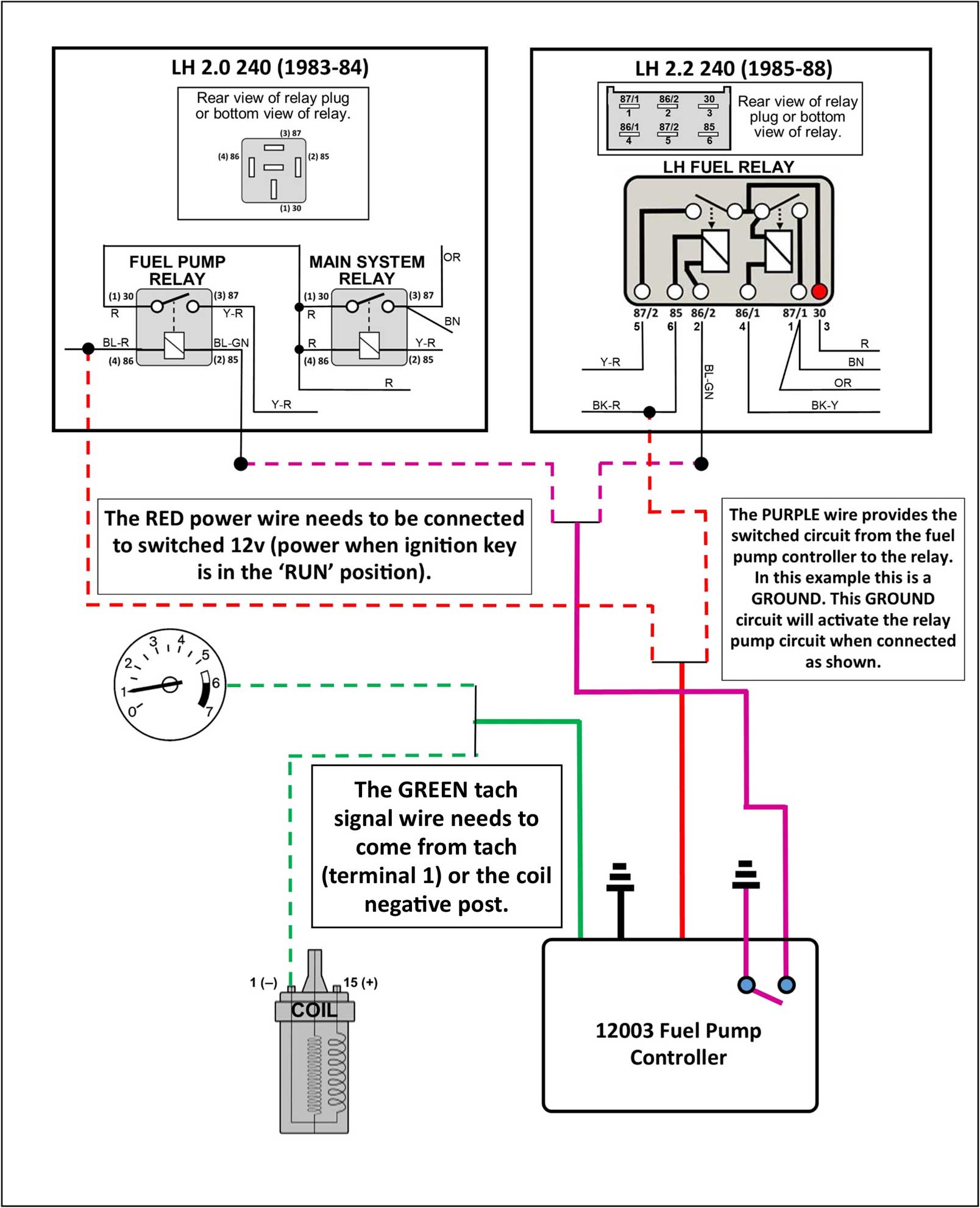
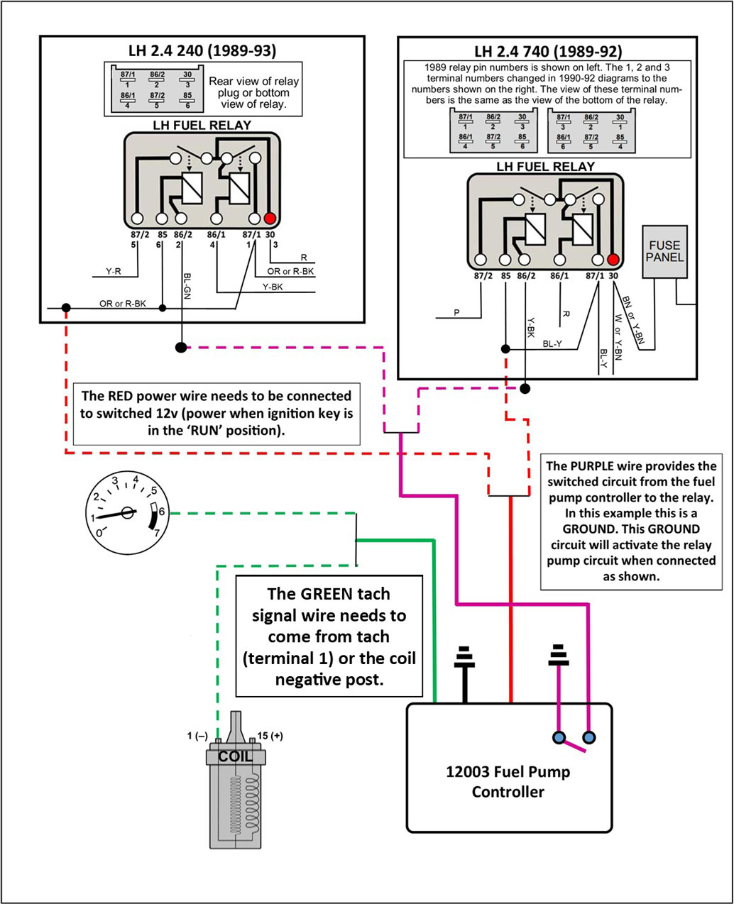
| FUEL PUMP POWER INFO FOR LH 2.2 or LH 2.4 +EZK 240 CONVERSION HARNESSES. This image below is intended to address questions about how power is typically provided to the fuel pumps when installing a stand-alone LH 2.2 or 2.4 +EZK 240 Conversion Harness in a 240 Turbo or other 240 which originally had K-Jetronic fuel injection. Please keep in mind there is more than one way to wire fuel pumps, but here I suggest a simple, easy to understand solution. CLICK IMAGE FOR LARGER PHOTO 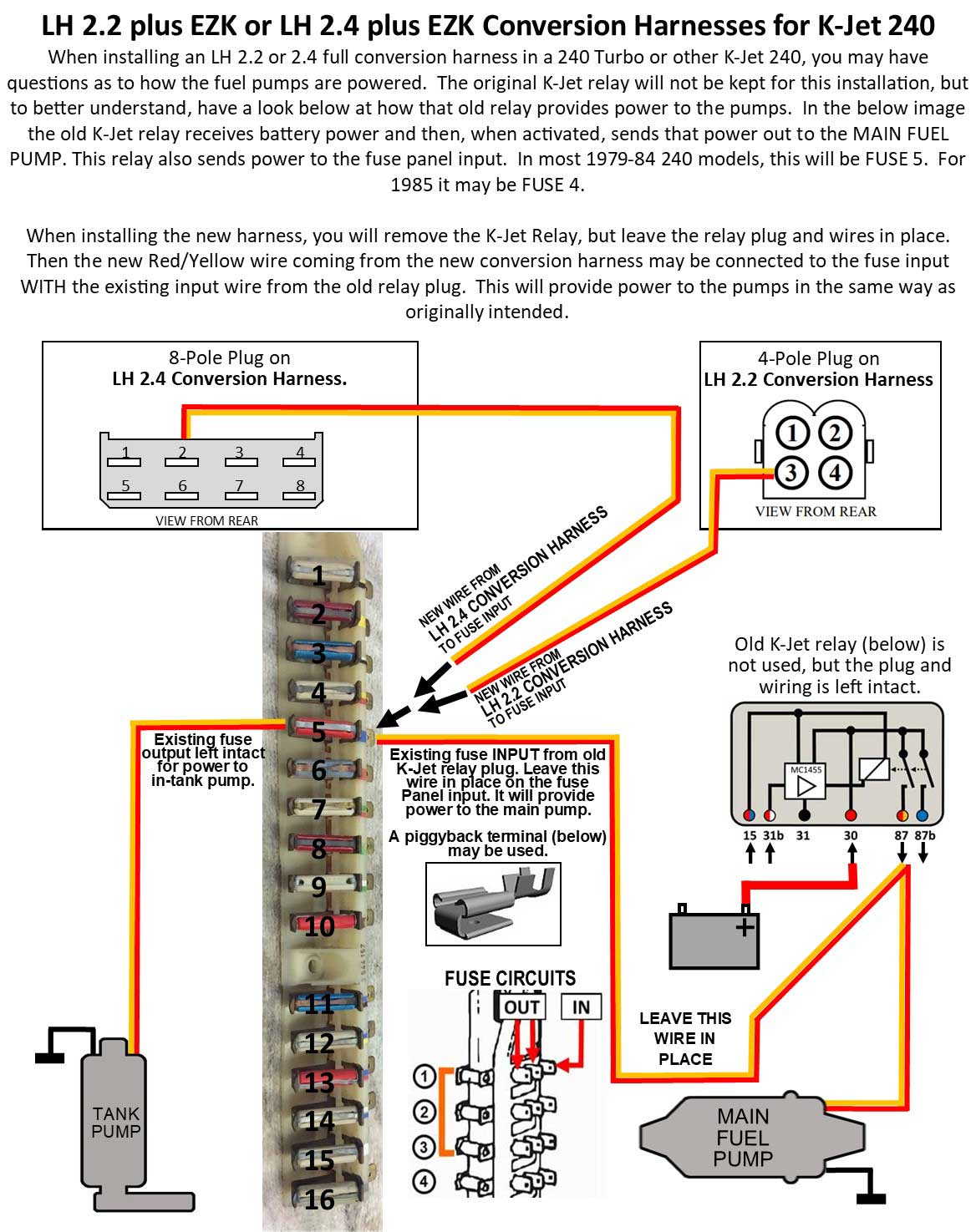 More information about wiring for LH 2.2 or LH 2.4 can be found in my Pin Function Diagrams HERE. |
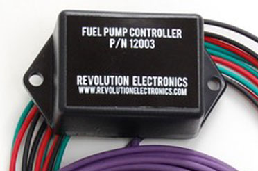
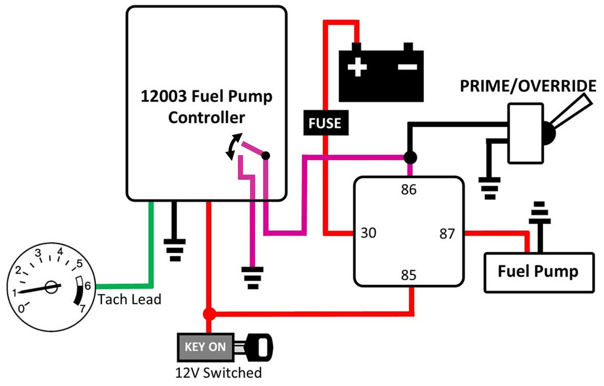
| Fuel Pump Controllers This section discusses reliable FIXES to common fuel pump control failures by some ECUs. You may find someday that you have a need for a universal fuel pump controller. A device like this will receive your ignition coil or tach signal and then reliably activate your fuel pump(s). This function is similar to what your K-JET RELAY or LH ECU should be doing, but sometimes relays or ECUs just plain don't perform like they should.
LH 2.2 or 2.4 LH ECU TEST VIDEO The below video offers a demonstration of how test your ECU by connecting a GROUND TEST WIRE to your 240 Fuel Pump Relay. This test works for LH 2.2 or 2.4. This acts as a diagnostic test for a car that won't start and if you suspect the Fuel Pump Relay is not being activated by the ECU when the engine is turning. The ground wire shown in this video should be connected to the BLUE/GREEN wire that goes to the fuel pump relay plug. Grounding the Blue/Green wire in this test simply replicates what the ECU is supposed to do when it activates the fuel relay. If grounding this wire changes things and suddenly your fuel pumps turn on, congratulations on finding the problem. https://www.youtube.com/watch?v=f2tCRejgFoU&feature=emb_logo Universal Fuel Pump Controller from Revolution Electronics. MORE DETAILS
|
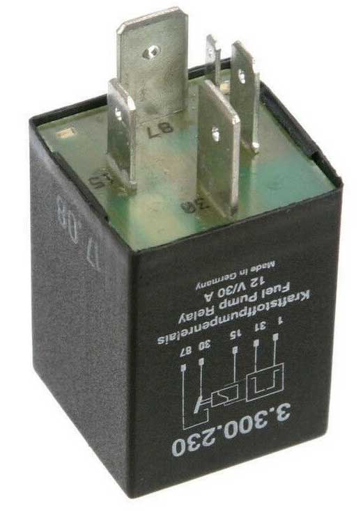
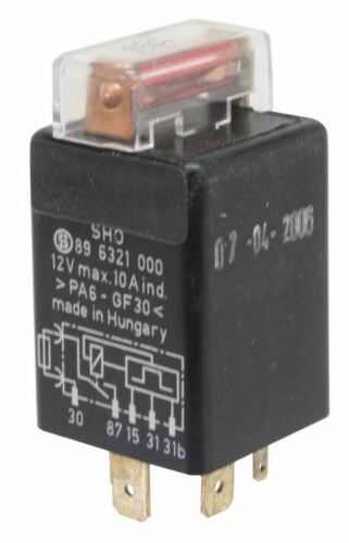
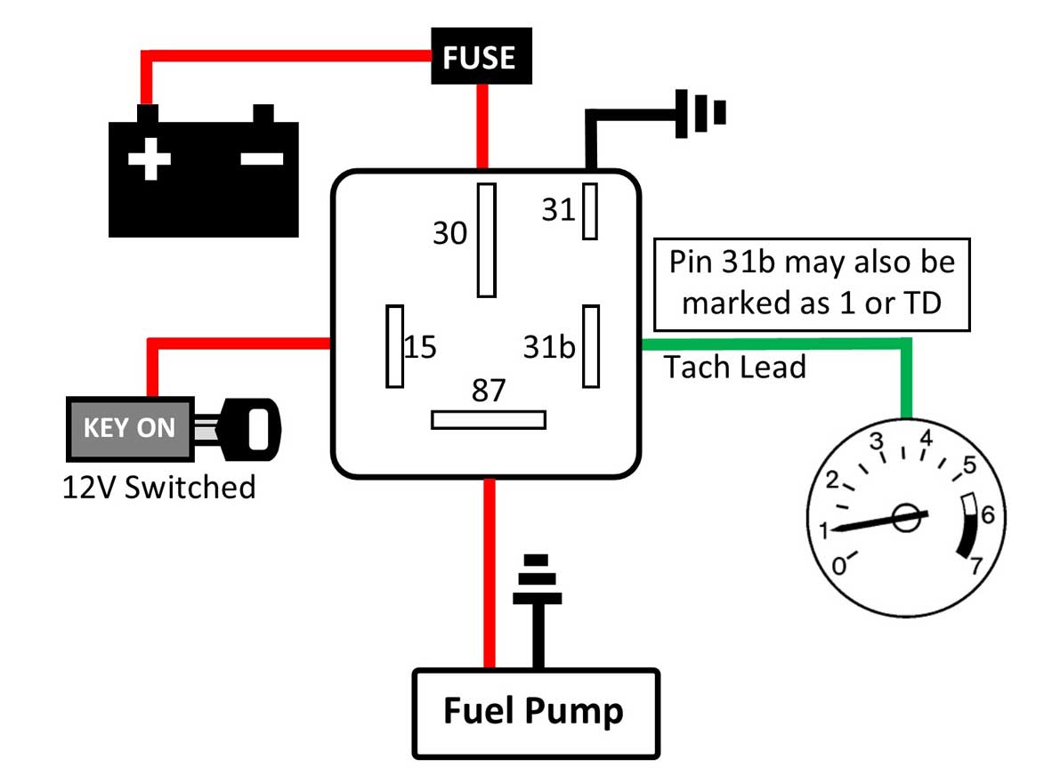
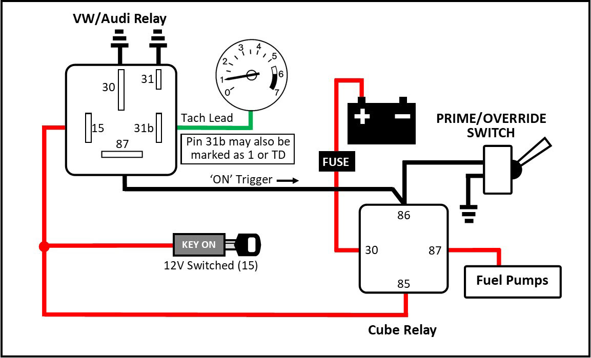
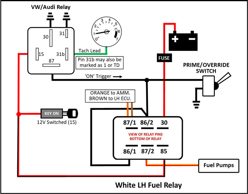
| VW/Audi Fuel Pump Relays (using a Tach Signal for activation) Here's an interesting existing VW fuel pump relay that will do a similar function as the above universal controller. It's much less expensive. I have NOT tried one of these, but I would probably have considered trying one if I had discovered it before buying the universal controller above. This relay is designed to receive a coil/tach pulse signal to activate a fuel pump circuit.
|
|
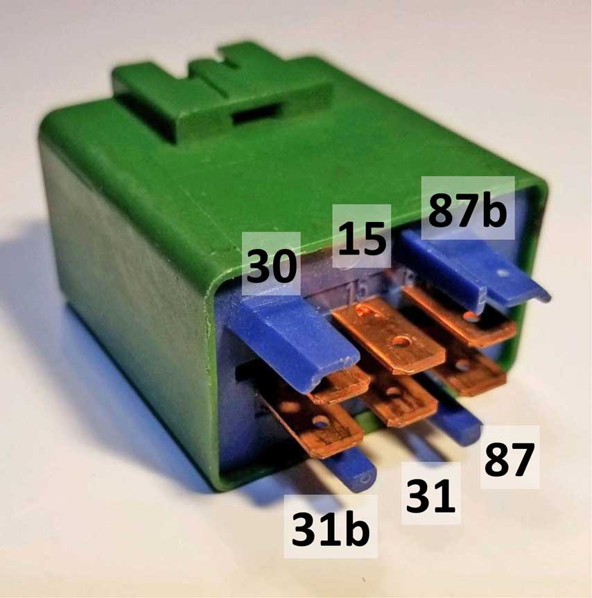
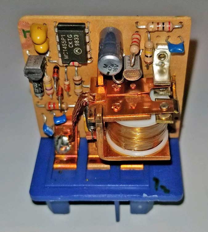
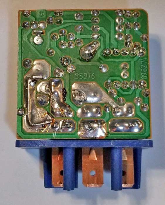
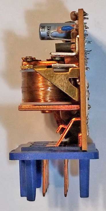
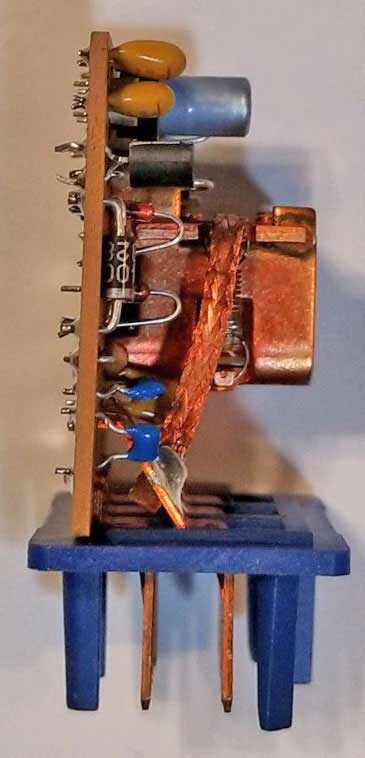
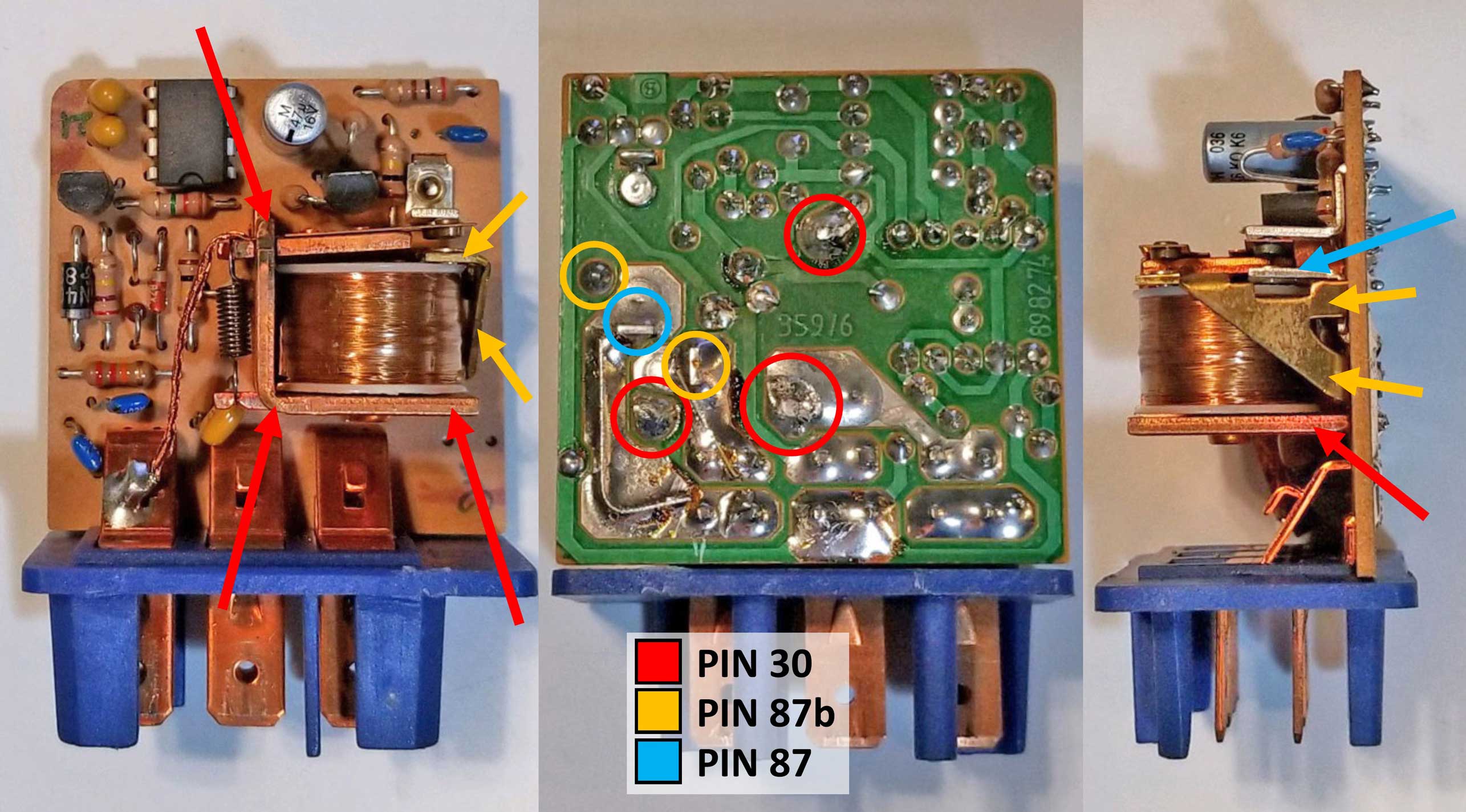
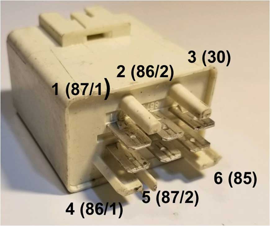
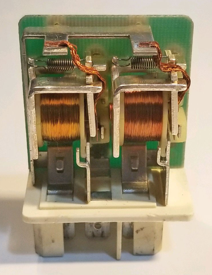
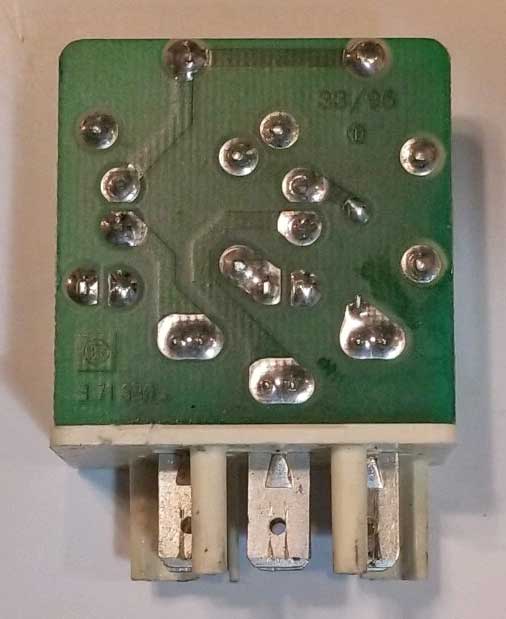
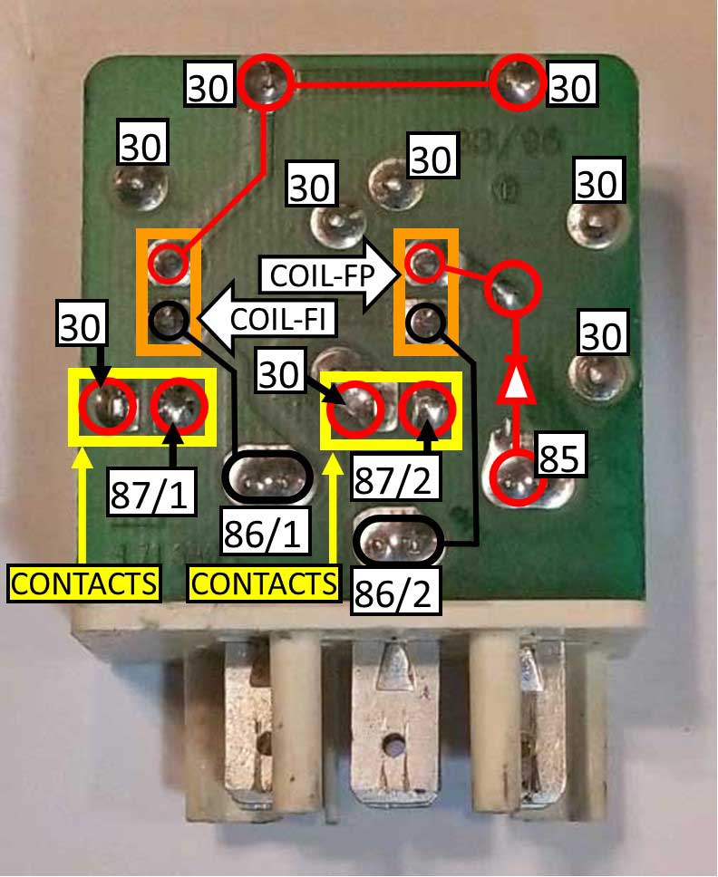
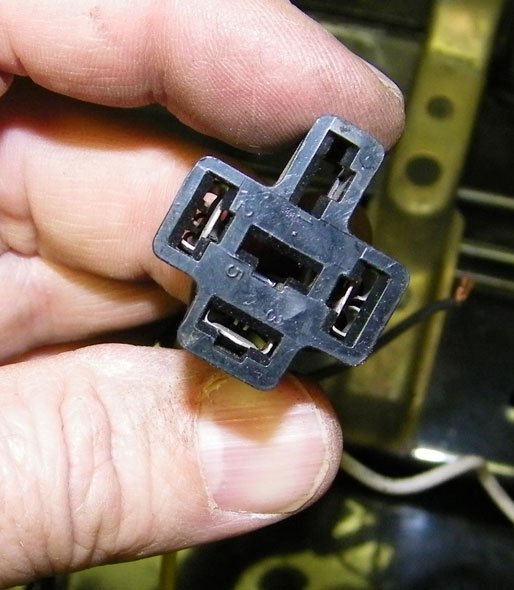
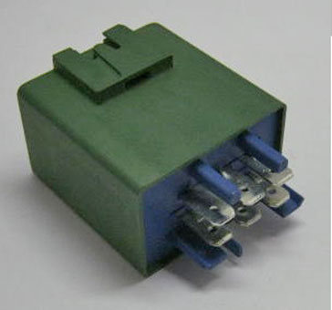
| Repairing a Bad Green K-Jetronic Fuel Pump Relay There is a fairly common fault in this fuel pump relay. Over the years the solder joints on the back of the board can develop small cracks. This is most likely due to a combination of vibration and heat cycles. The cracks can usually be seen if you look very close or use a magnifying glass. These cracks will cause intermittent problems. The most common cracks seem to be where the RED circles are below. The three RED circles are the points where the coil frame is anchored to the board. In particularly bad cases these cracks can cause the coil to rattle around on its mounting points if you shake the relay. The coil frame is connected to Pin 30. The less common places to watch for cracks are the other colored circles. The YELLOW circles are connected to Pin 87b and the BLUE circle is connected to Pin 87. You can use a simple soldering iron to heat and re-flow the solder at any point you suspect might be cracked. This will cure any issue that was caused by a crack.
|
|
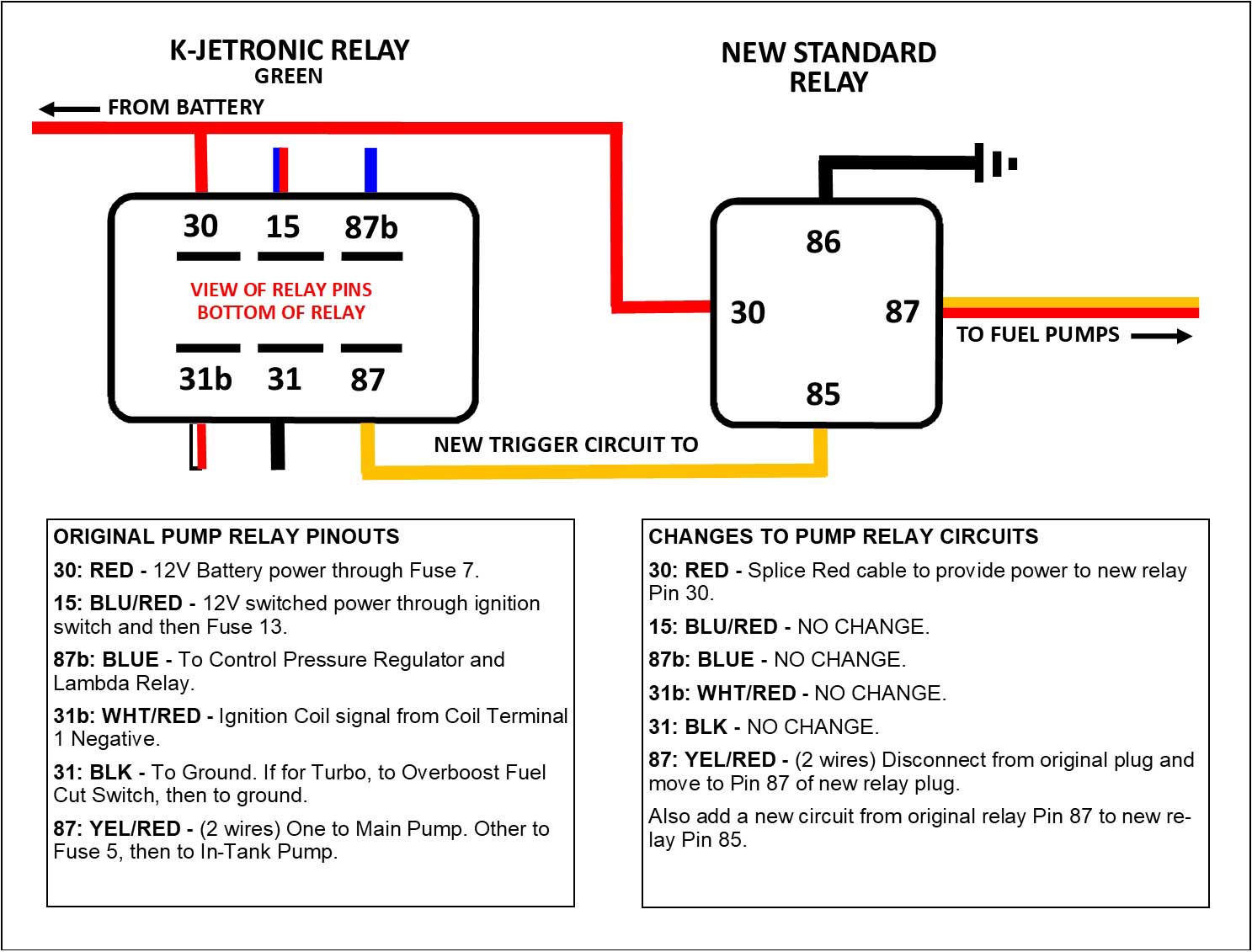
Using Common Relays in place of the White Stribel Relay
Yes, there are cheap Chinese copies for less. Are those reliable? Don't know. So if you ever find the need to use something else in place of that white Stribel Relay, here's a diagram below that will show the use of two common cube relays instead. These can be 4-pin or 5-pin relays, because only 4 pins are used. Notes regarding DIODE: If you open the Stribel relay you'll see there's a diode soldered to the board on the fuel pump side. It is in-line between Pin 85 and the fuel pump coil. It's function appears to protect the fuel ECU from potential EMF flyback voltage from the coil. Adding a similar diode to the fuel pump circuit when creating a cube relay replacement seems to be prudent. A suggested diode is IN4001 through IN4007, which can be found online for under $10 for a pack of 100. Keep in mind that the correct polarity shown below must be followed. Further info may be found in the following forum discussion: turbobricks.com/replacing-factory-fuel-pump-relay-with-bosch-relays.349135  |
|
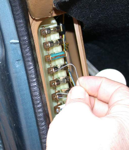
| Bypassing or Jumping a Fuel Pump Relay How to "JUMP" or BYPASS the fuel pump circuit from your Volvo 240 FUSE PANEL: The fastest method to make the main fuel pump run (bypassing the Fuel Pump Relay) is by jumping two circuits at the fuse panel. The KEY DOES NOT need to be 'ON' for this to work. In an emergency you can make a jumper wire from a piece of wire with stripped ends or even a straightened paperclip. Jumping the circuits on the RIGHT side of the fuses will offer the best results, but usually either side will work. 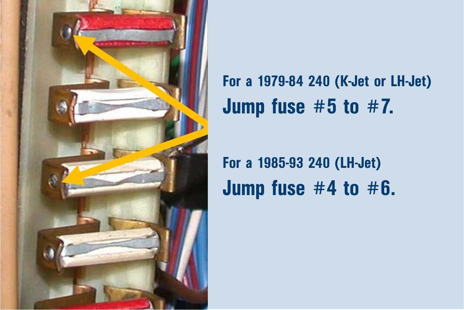 More info, see diagrams below.
JUMPING A MAIN FUEL PUMP FROM the 240 Fuel Pump RELAY PLUG If you find that the above jump test makes your fuel pump run and you don't have a spare relay with you (or if your spare doesn't work either), here's a trick that will get you home. The simple trick of course is to keep a jump wire (or paper clip) in place while driving. If you can manage to do that, your pump will run continuously and you can drive the car without any adverse affect. This won't hurt anything it as long as you have fuel in the tank. Keep in mind that when you turn off the car with a jumper wire in place, your fuel pump will continue running until you disconnect the jumper. 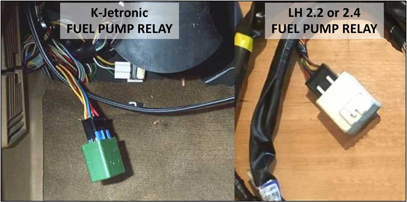
1977-78 240:
Step 1. Find your fuel pump relay and unplug it. Step 2. Look at the plug and the wire colors going into it. There will be a RED wire going into one of the terminals. That is the power from the battery. Also find the YELLOW wire. The YELLOW wire goes to the fuel pumps. Step 3. Jump or connect the RED WIRE to the YELLOW WIRE. This should instantly power the pumps ON (the key does NOT need to be ON). 1979-93 240: Step 1. Find your fuel pump relay and unplug it. Step 2. Look at the plug and the wire colors going into it. There will be a RED wire going into one of the terminal inserts. That is the power from the battery. Also find the YELLOW/RED wire(s) (there may be TWO of this YELLOW-RED wire going into ONE terminal). These wires go to the fuel pumps. Step 3. Jump or connect the RED WIRE to the YELLOW/RED WIRE. This should instantly power the pumps ON (the key does NOT need to be ON). 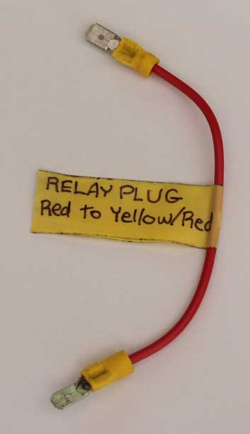 <<<
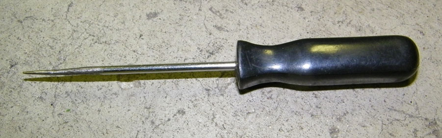
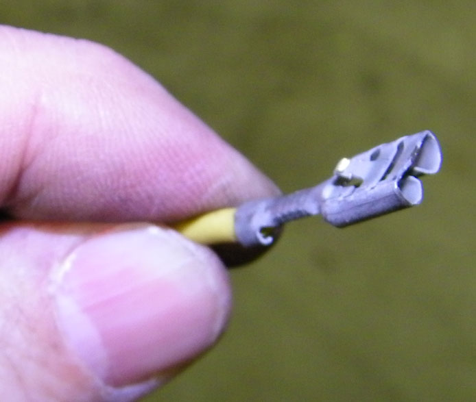
Here's a
simple tool you can make
yourself and throw in your glove box. I have
one in mine. It's at simple jumper made with TWO .250 inch (6.3 mm) MALE crimp terminals
and a piece of wire (14 gauge wire will do). <<<
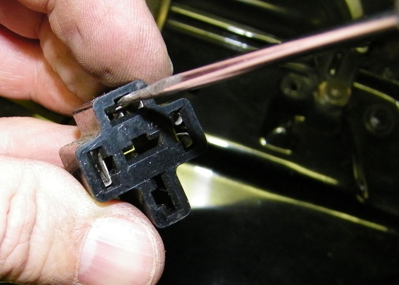
Here's a
simple tool you can make
yourself and throw in your glove box. I have
one in mine. It's at simple jumper made with TWO .250 inch (6.3 mm) MALE crimp terminals
and a piece of wire (14 gauge wire will do). These male terminals will plug right into the relay connector slots after the relay is unplugged. It might be a long while before you use it, so put a tag on there to remind yourself that it should jump the RED to the YELLOW/RED wire (or RED to YELLOW wire for pre-1979 240). If you are experiencing any mysterious electrical issues, here is a really good discussion thread on diagnosing a problematic late model 240 fuel pump circuit that was eventually solved: turbobricks.com/1991-240-fuel-pump-mystery.287210 |
|
Adding a Secondary
Relay to take the High Load off your 240 Fuel Pump
Relay
This is not for everyone, but it seemed to help for me for many years. 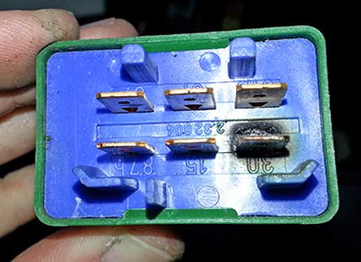 <<<
The fuel pump relay in your 240 takes a lot of
abuse and it's expected to run your fuel pumps for
years and years without fail. They do fail, but
usually not because they wear out. Most fail because of unwanted heat
after years of
use. They often run hot
because; 1. They handle a heavy load. 2. The heat
causes their plug connections to develop higher
resistance, which then causes more heat, which then makes a
failure begin like the melted terminal in this photo. <<<
The fuel pump relay in your 240 takes a lot of
abuse and it's expected to run your fuel pumps for
years and years without fail. They do fail, but
usually not because they wear out. Most fail because of unwanted heat
after years of
use. They often run hot
because; 1. They handle a heavy load. 2. The heat
causes their plug connections to develop higher
resistance, which then causes more heat, which then makes a
failure begin like the melted terminal in this photo. What this extra relay mod does is take the heavy load off of the expensive Volvo relay and puts it on the inexpensive standard relay. This allows the Volvo relay to be used as a low current switch to activate the standard relay, which will handle the load instead. The new extra standard relay is triggered by pin 87 from the original fuel pump relay and receives its main battery power from pin 30 of the original relay circuit. As an option, you may instead run a dedicated battery wire to pin 30 on the new relay. I suggest 12 gauge wire. If you do this, then I recommend a fuse between the battery and relay. Below I have outlined how I added a standard inexpensive 4-pin cube relay (or 5-pin will work too) to handle the pump load, giving the original expensive fuel pump relay a much welcomed rest. The new added relay can be any standard 4 or 5 pin type relay with a load rating of 15 amps or higher. |
||
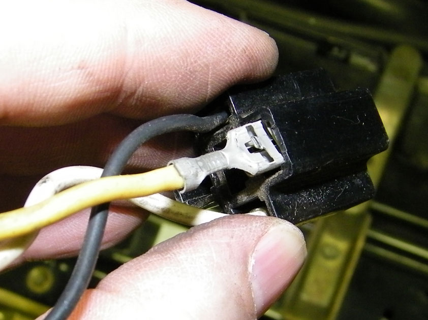
 <<< Here's
a pic of what that heat can do to the relay plug. This is
extreme. Most of the time the melt damage to the plug is minor, but it
can get bad. <<< Here's
a pic of what that heat can do to the relay plug. This is
extreme. Most of the time the melt damage to the plug is minor, but it
can get bad.But even if you do NOT feel this mod is right for your car, please read the info BELOW on using Anti-Corrosize Zinc Paste on your electrical connections. I strongly believe this paste would have prevented the damage in these photos. |
||
| What this extra relay mod does is take
the heavy load off of the expensive Volvo relay and
puts it on the inexpensive standard relay. This allows the Volvo relay to be used as a low current switch
to activate the standard relay, which will handle the load instead. The new extra standard relay is triggered by pin 87 from the original fuel pump relay and receives its main battery power from pin 30 of the original relay circuit. As an option, you may instead run a dedicated battery wire to pin 30 on the new relay. I suggest 12 gauge wire. This should provide a bit more voltage to your pumps. If you do this, then the wire should always contain a fuse between the battery and relay. |
||
K-Jetronic (Mechanical Injection) Relay Mod with Second Relay
 |
||
 |
||
|
|
||
| Some info about INERTIA SAFETY SWITCHES Beginning in the late 1980s a number of vehicle manufacturers began using an inertia switch as a fuel pump safety device. It was designed to shut off the fuel pumps in case of an accident. The Volvo 240 NEVER came with any such device. 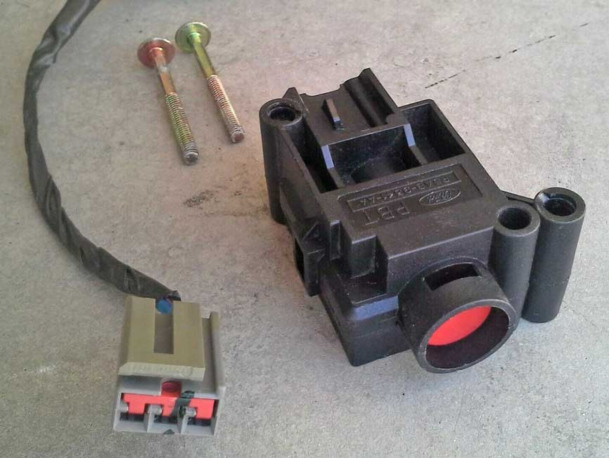 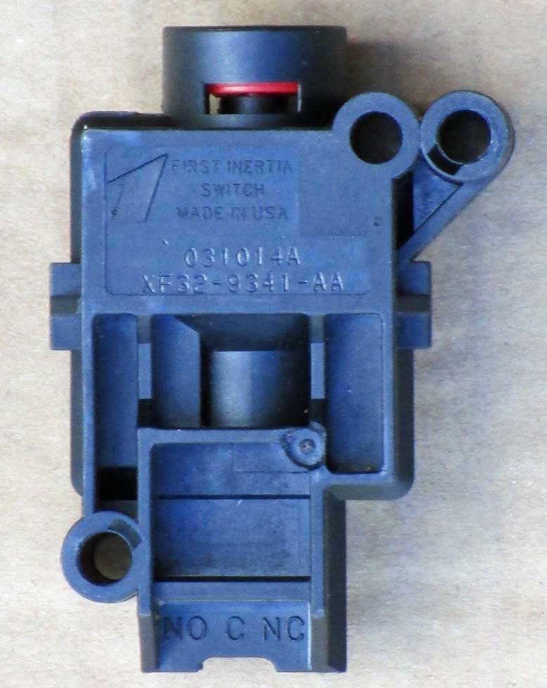 This switch above is made by First Inertia and I believe it was used in a number of different cars and trucks, including Ford. Searching on-line for a Ford intertia switch will usually find one just like this. This switch uses an internal magnet to keep the switch engaged. A sudden shock from any direction will disengage it. The switch may then easily be reset by pressing the red button. A switch like this with a wire connector pigtail can be found used in a salvage yard or on-line. An inertia switch like this may be wired as a NORMALLY OPEN or NORMALLY CLOSED switch. In most cases it will be wired in a NORMALLY CLOSED configuration to power a fuel pump or fuel pump relay. Some manufacturers have used similar switches in a normally open configuration to activate passenger safety devices in a collision, typically to pre-tension seat belts or to activate air-bags. If you were to use something like this in an old Volvo, be sure to mount it to a solid place on the body, preferably in a convenient place that you can access easily if you need to reset it. 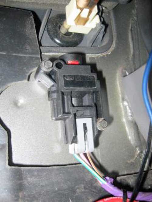 Since nothing is better than a good video, here's one about wiring an inertia switch. https://www.youtube.com/watch?v=MHgMHE6TUG8 |
||
| ANTI-CORROSIVE
ZINC PASTE If we can just just keep our electrical connections clean and tight, almost all of the electrical issues would be gone forever. That would be nice, right? 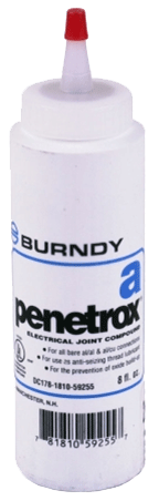 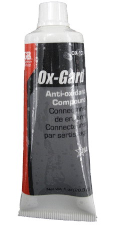 I
have owned a number of Volvos
over the last 30 years and my
current 240 is way over 30 years
old. It almost never has
electrical problems. Nothing
like the endless numbers of
other 240s out there that I hear
about so often. What's the
difference you ask? The
difference is that my 240 has
been always garaged all of its
life. Why is that
important? Because leaving
any car out in the open elements
for years and years slowly
introduces corrosion to grounds
and power connections until
things begin to go wrong. I
have owned a number of Volvos
over the last 30 years and my
current 240 is way over 30 years
old. It almost never has
electrical problems. Nothing
like the endless numbers of
other 240s out there that I hear
about so often. What's the
difference you ask? The
difference is that my 240 has
been always garaged all of its
life. Why is that
important? Because leaving
any car out in the open elements
for years and years slowly
introduces corrosion to grounds
and power connections until
things begin to go wrong.
So if you own one of those cars that has been outside forever, it's not too late. You can still clean as many grounds and electrical connections as possible. And while you're at it, I recommend that you smear a little anti-corrosive zinc paste on those connections. Many people in the Volvo community gravitate toward Ox-Gard, which does a similar job. The below information was contributed by Ron Kwas and should come in very handy to old Volvo owners: Anti-Corrosive Zinc Paste (a generic name for zinc dust contained in a grease) was originally developed for and later required by electrical codes for use on alumunum to copper electrical connections (or other dissimilar metal connections). No, it's not the same as Dielectric Grease, which is often incorrectly recommended. Dielectric Grease can offer some protection in the form of encapsulation from moisture, but it also carries with it the potential disadvantage of locking in moisture or corrosion which may have already begun. Anti-Corrosive Zinc Paste (or ACZP) is the next evolution of the encapsulation principle, because zinc (the lowest on the Galvanic nobility chart) neutralizes corrosion on a micro-scale to truly protect connections on a long-term basis during the encapsulation, INCLUDING an added protection from corrosion which may otherwise begin to form in that connection. Ron uses and recommends Penetrox A (by Burndy). Many Volvo fans are familiar with Ox-Gard, which is a similar zinc compound. Ron and I are huge advocates of treating ALL electrical connections on our cars (except of course High Voltage Ignition connections) with a suitable version of this material. You can learn more about this stuff at Ron's page here: http://www.sw-em.com/anti_corrosive_paste.htm |
| 240 Main Fuel Pump Info If your 240 needs a new main fuel pump, the huge amount of on-line info can be very confusing. This information will try to help. If you can help improve this info, offer comments from pumps you have used, etc, please email me: CONTACT
This image BELOW comes from a Bosch Classic in-line fuel pump catalog, which is linked below.  The first EKP column above appears to represent an original Bosch part number assigned for the car. The EPK UNI column appears to represent later Bosch UNIVERSAL pumps which are available as REPLACEMENTS for pumps that might be NLA. Above image is from Bosch Classic Fuel Pumps (25 pages) PDF, page 18: www.bosch-classic.com/minikatalog_kraftstoffpumpe.pdf  MORE VOLVO 240 MAIN FUEL PUMP DATA
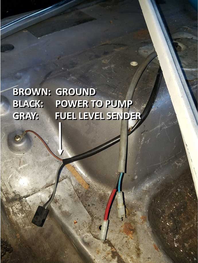
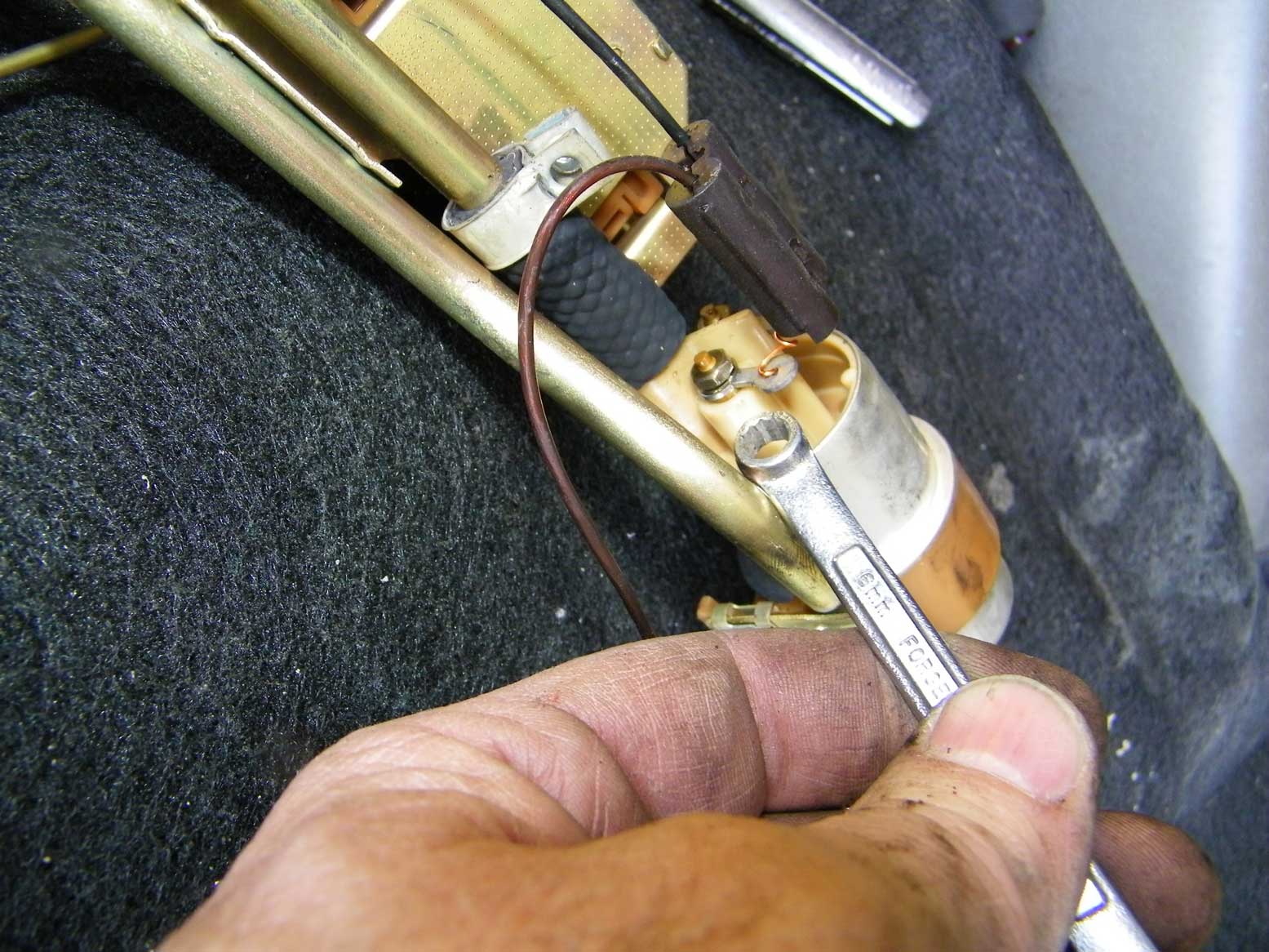
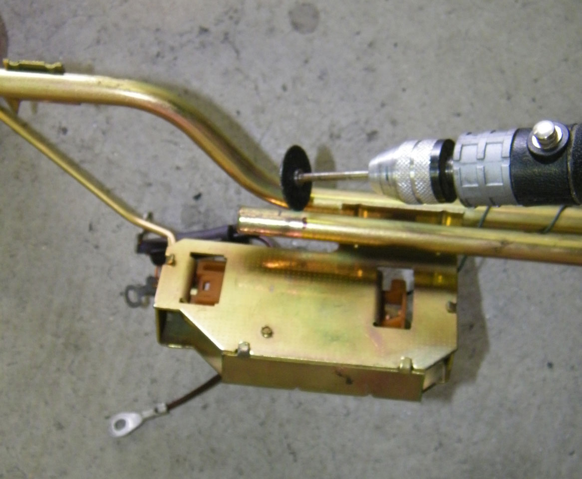
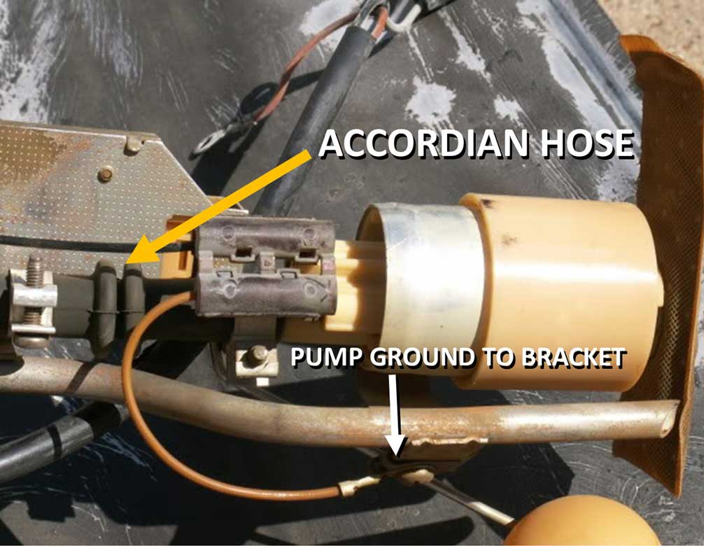
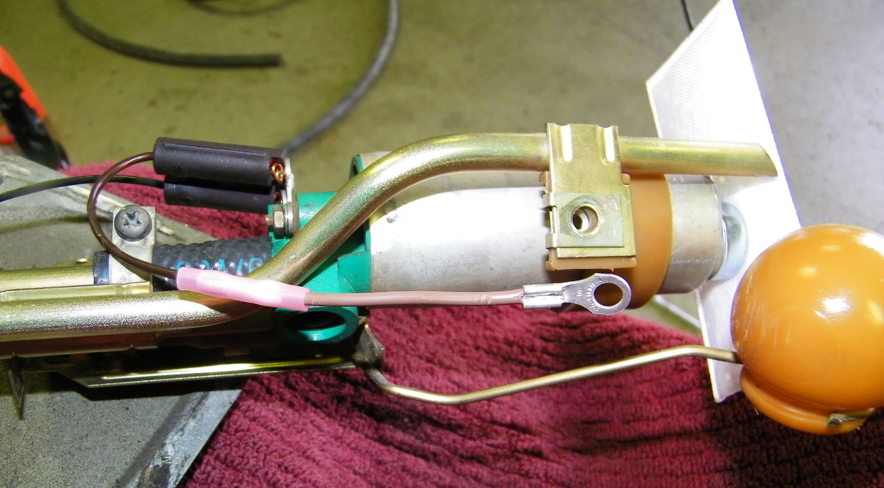
Volvo 240 Main Fuel Pump Dimensions and Fittings.  Some new replacement pumps may come with the above shown THREADED power and ground posts (sized as M4 and M5), which use 4 mm and 5 mm crimp ring terminals. You may find that your original Volvo/Bosch pump uses these BULLET electrical connectors below for the electrical connections. Some replacement pumps will come with this type of connector too, but many will come with the above threaded posts instead. If you get a threaded post pump, you may need to splice on some crimp ring terminals onto your original wires.  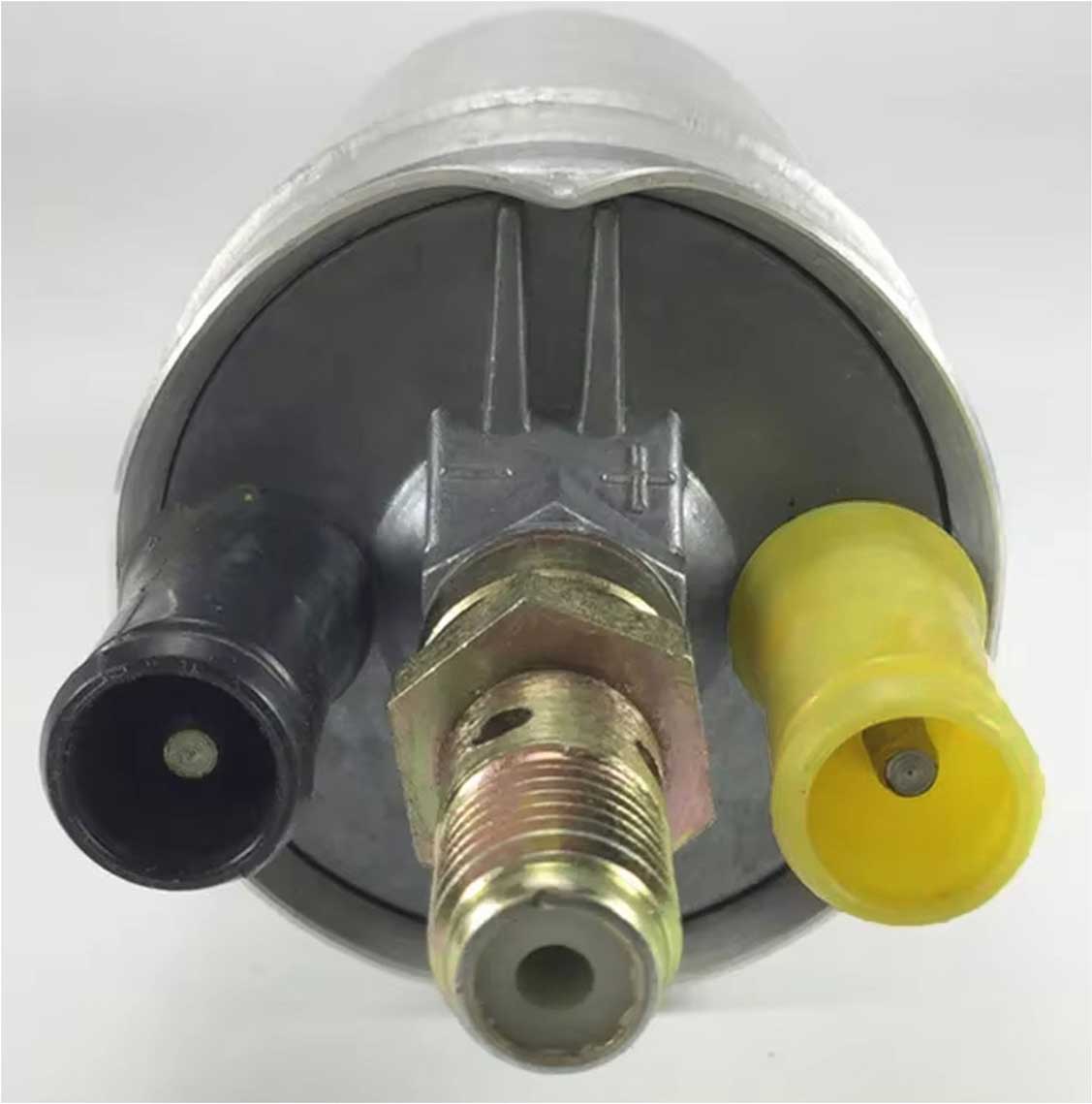 If you need more information about a 240 Main Pump Wiring Harness or the original pump electrical connections, or if you need a main fuel pump harness, I have that info in my Wire Harness Page at www.prancingmoose.com/volvoharnesses.html#9139233. 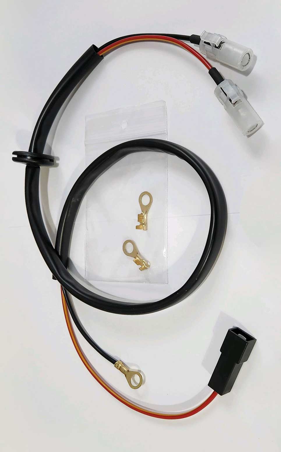
This is a CHECK VALVE FITTING. Same as shown on the ABOVE pump image. 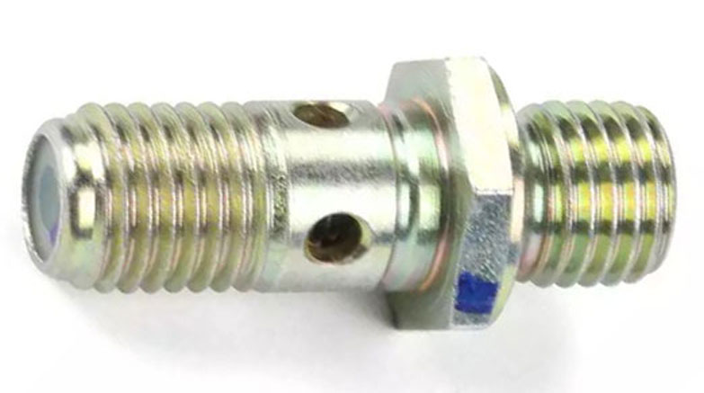 This fitting connects to a fuel hose using a BANJO type fitting. This check valve fitting can be ordered as a separate part if needed. This one is Volvo PN 1306990 (or Bosch 1 583 386 514). The thread for this going into the pump is M12 x 1.5 and it uses a copper crush washer. The outflow fitting thread on this is also M12 x 1.5. If you are using a BANJO type fitting like this one, it will look like these fuel pump images BELOW when installed. These pumps below are accompanied by Fuel Accumulators. A Fuel Accumulator was used with K-Jetronic systems and it helped to maintain steady fuel pressure. With this type of system, the Fuel Filter was placed in the engine bay. 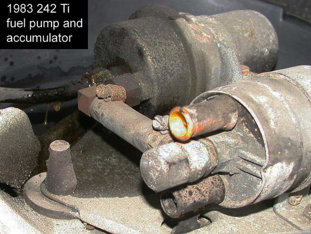
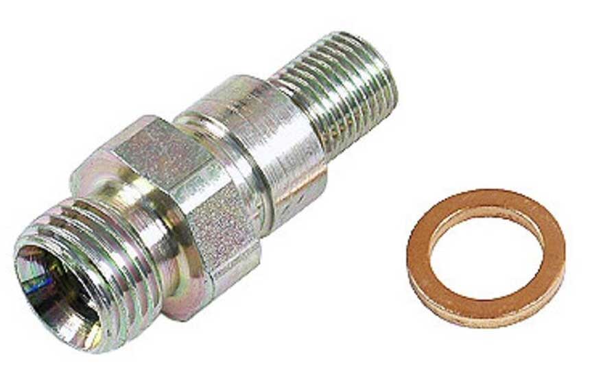
Above right image found in: https://turbobricks.com/index.php?threads/bosch-fuel-pump-check-valve-fitting.233035/ If needed, a CHECK VALVE FITTING may be removed from a Bosch fuel pump and changed for a different type. CHECK VALVE FOR LH EFI The check valve fitting shown BELOW will usually be found on LH-Jetronic (EFI) system 240s. This check valve fitting is Volvo PN 1326899 (or Bosch 1 587 010 539). The threads going into the pump are M12 x 1.5 and it uses a copper crush washer. The outflow thread on this fitting is M14 inverted flare. This type is more commonly found on pumps for LH-Jetronic EFI cars.   This fitting will look like this image below then it's mounted in the car. This pump below is accompanied by a Fuel Filter.  This image comes from the following Turbobricks 240 project page: turbobricks.com/my-240-story.305369/page-4. |
||||||||||||||||||||||||||||||||||||||||||||||||||||||||||||||||||||||||||||||||||||||||||||
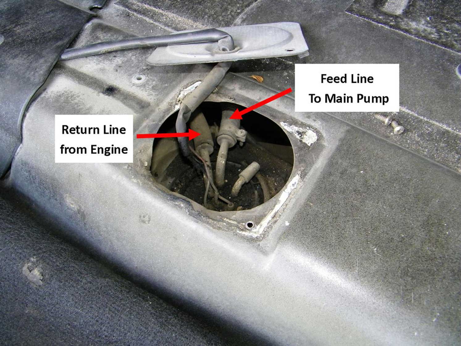
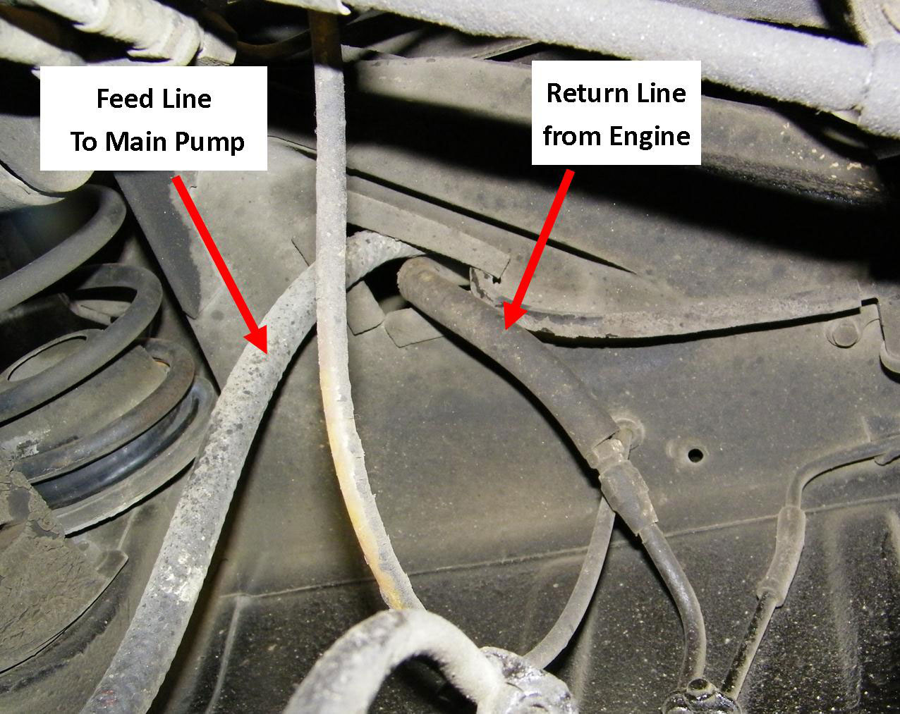
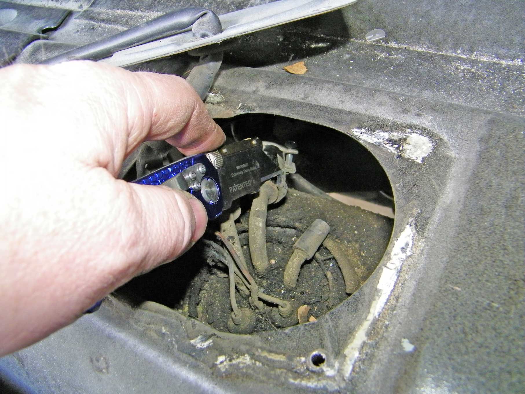
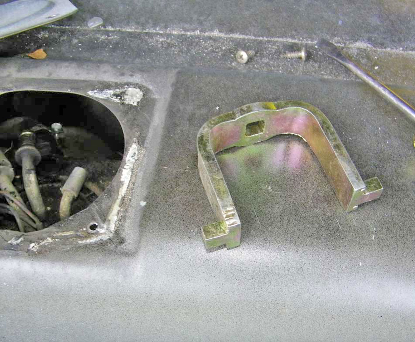
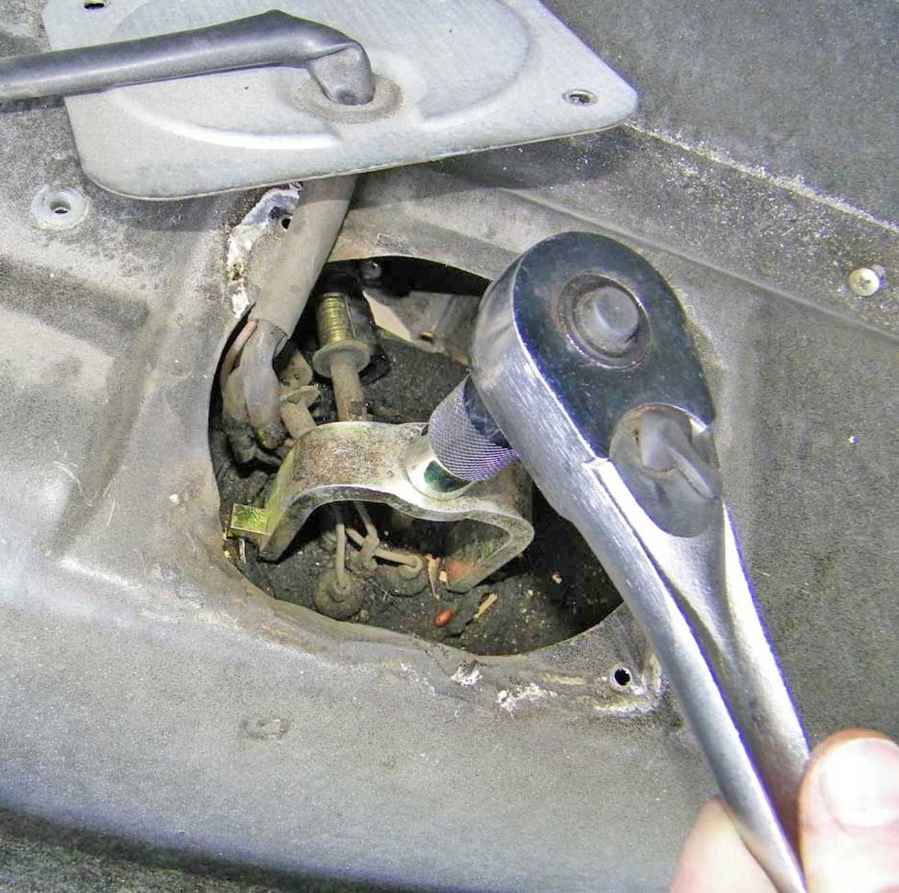
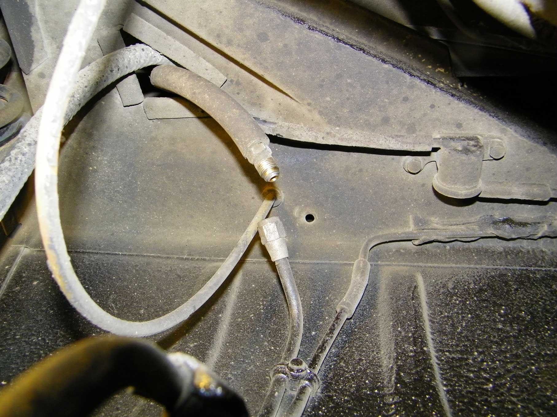
| 240 MAIN FUEL PUMP and FILTER REPLACEMENT A good look at how to remove/replace the main fuel pump. This car is a 1988 240, which has the main pump and fuel filter in the same location under the car just ahead of the left rear wheel.
|
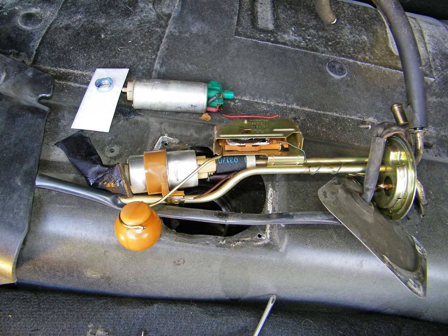
| 240 IN-TANK FUEL PUMP REPLACEMENT A good look at how to remove/replace the in-tank fuel pump. This car is a 1988 240. The procedure will not generally be different from earler 240s.
|
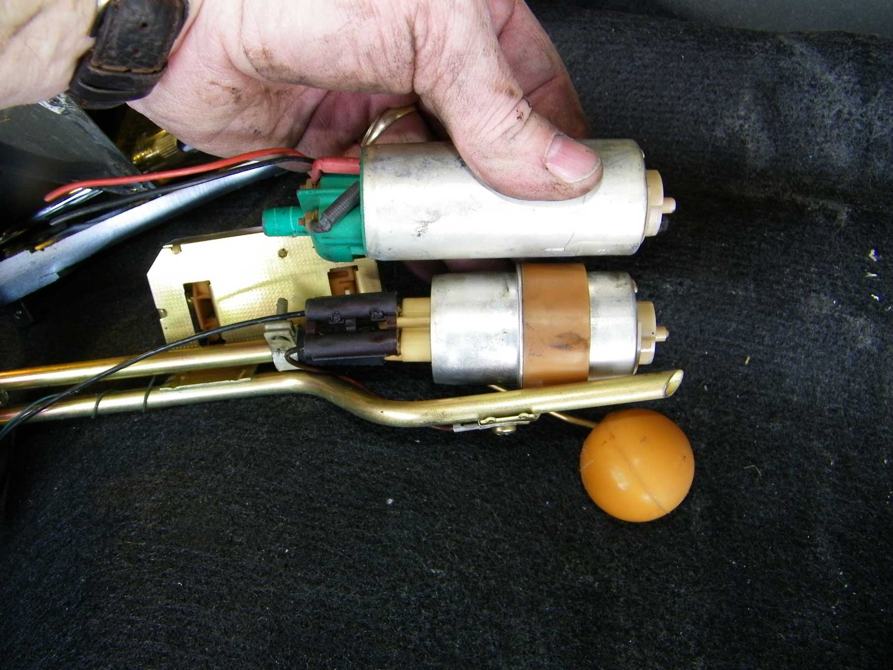
Upgrade the In-Tank Fuel Pump in your 240
with a Larger 740 Turbo Pump
This work below is showing a mod I did in my 1984 240 Turbo. The Bosch in-tank fuel pump found in your 240 Turbo will be the same pump used in all 240/260 models from 1976 to 1984. It's very small and while it will provide adequate fuel to the main pump for a non-turbo Volvo, it has been considered by many to be too small for a turbo motor with any increased engine performance. The Volvo part number for the original 240 in-tank pump up to 1984 is 1276330. In 1985, that part number changed to 3507436, which was used in all 240s until 1993. The used 740 Turbo pump I used for this conversion, which was used in 1986 and later 700 and 900 Turbo models (and 960), is PN 3517845. I got mine from a salvage yard. This pump retails new for between $150 and $200. It is also widely available in salvage yards for a lot less, although you should be cautious, because some pumps found in salvage yards may be dead. I chose to install a used pump from a salvaged Volvo due to cost. A good tool to bring to a salvage yard to test electrical parts like this is a drill battery. If you need to test a pump, do it very briefly... only for a second. These pumps are not designed to run dry and it can damage them quickly. Here are a couple videos that might help. https://www.youtube.com/watch?v=F7BqPr3X0AE
G E T T I N G S T A R T E D
CONTACT Thanks, Dave MORE USEFUL LINKS ON THIS SUBJECT http://cleanflametrap.com/transferPump.htm |
| Fuel Pump Check Valve Info The Volvo 240 uses a fuel pump check valve in the main fuel pump to maintain pressure beyond the pump when power is off, so the fuel in the line doesn't drain back into the tank. Sometimes a fuel injected 240 will begins to have a problem with fuel pressure. Specifically it may result in longer cranking to start the car. The most common diagnosis for this is a failing FUEL PRESSURE REGULATOR. Sometimes the problem actually IS a bad fuel pressure regulator, but NOT ALWAYS. Keep in mind that there's also a CHECK VALVE in the main pump which can fail. Failure can be from debris or foreign material lodging in the valve or sometimes the valve parts can disintegrate from long use.
|
|
| Replacing a Fuel Pump Check Valve https://www.youtube.com/watch?v=qIW3VgovsYM |
|
Early Fuel Pump, Check Valve and Fuel Accumulator Info. Plus How to ELIMINATE the FUEL ACCUMULATOR. https://www.youtube.com/watch?v=SpSnQ67C17c Here are some useful diagrams below (5 PAGES) beginning with 1975 K-Jetronic 240 fuel pump, check valve and fuel accumulator. (PDF, click to open or right-click and save as) 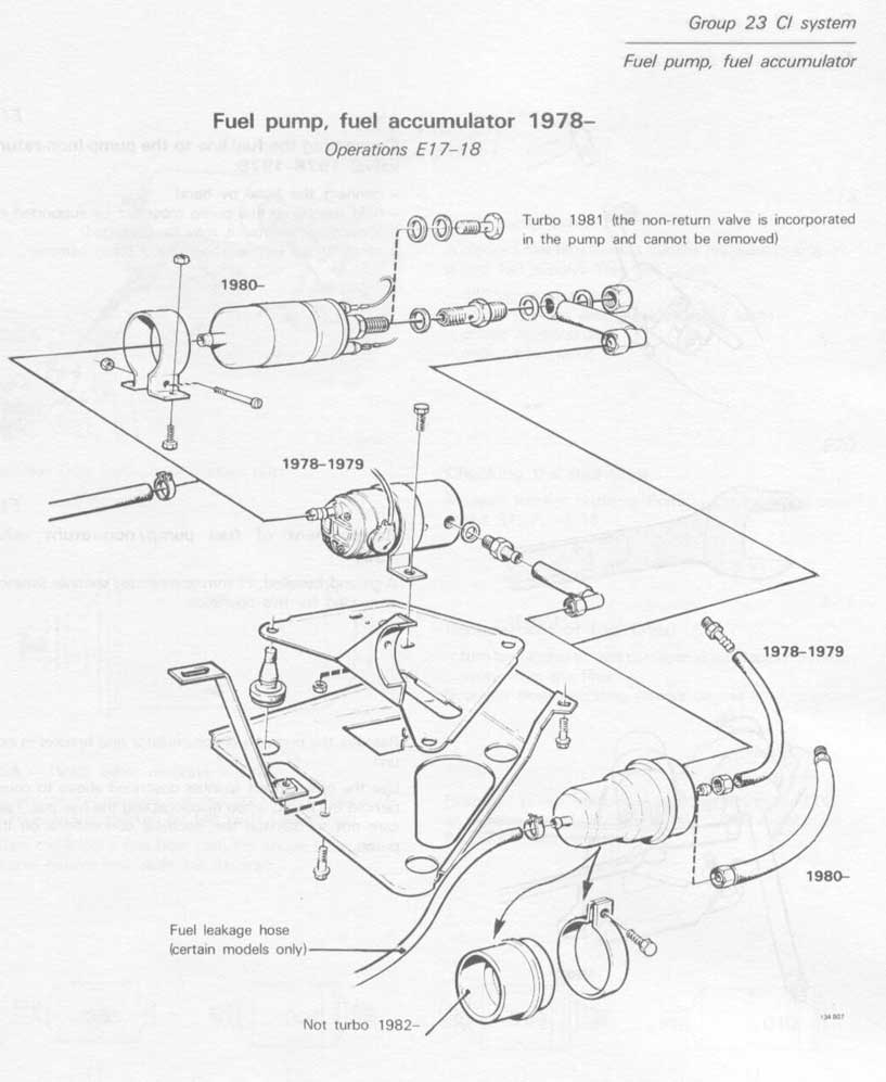
|
|
|
||||
| davebarton.com |
prancingmoose.com |
240turbo.com |
Special Emblems |
|
| Prancing
Moose Stickers |
Volvo
Stickers |
Body/Chassis/Engine
Labels |
240 MODS and FIXES Page | |
| Other Car Brand
Stickers |
Steering
Wheel Labels |
Center Cap Labels/Overlays |
Cool Volvo
Products |
|
| Grill Labels/Overlays |
Volvo Wire
Harnesses |
Conversion Harnesses |
Harness
Parts/Connectors |
|
| Volvo Relays |
Coil Repair
Harnesses |
240 Window
Scrapers |
740/940
Window Scrapers |
|
| Adjustable Voltage
Regulators |
Horn Buttons |
240 Odometer
Repair |
740 Odometer
Repair |
|
| Volvo Gauge
Faces |
740
Turbo/Boost Faces |
240 Black Door Vinyl |
850 Odometer
Repair |
|
| ALTERNATOR Page |
240 Power Mirrors - Switches |
240 Oil Cooler Page |
240 Fuse Panel Page |
|
| Group A
Racing 242 Turbo Page |
240 Hydraulic Clutch | Fuel Pump RELAY Page |
240 Headlight RELAY Page |
|
| Used Parts & Extra Stuff for sale |
CRIMPING Page |
240 Ignition Page |
240 Headlight Page |
|
| 240 Gauge Electrical Diagrams | 240 REAR END Page | Yoshifab Catch Can Install | 240 TAILLIGHT Page | |
| Side Marker
Lights Page |
Gentex Mirror Upgrade | Yoshifab Drain Tube Install | Modified 240 Favorites | |
| SoCal Salvage Yards | Unleaded Racing Fuel | B26FT Stroker | Dave's 245 Spec Page | |
| 240 SUSPENSION Page | 240 Lowering Page |
240 Windshield Page |
240 WIPER Page | |
| 240 BRAKES Page |
240 Dash Top Gauge Pod | Cadillac 4-Note Horn Install | 240 DYNAMAT Installation | |
| 4 Speed Fan
Controller |
Electric Cooling Fan
Page |
BRUSHLESS Cooling Fan Page |
Tropical Fan
Clutches |
|
| 240 AC Page | "KOMFORT BLINKER" Upgrade | T5 Trans Conversion Page | 240 Engine Mount Page | |
| 240 VIN Page | Stepper Idle Valve Page |
Vacuum Diagrams | 240 HOOD Page | |
| 240 Exhaust Page | 242 Power Vent Window Project |
EFI Volvo Pin Function Diagrams |
Favorite Links | |
| R-Sport
Apparel |
Prancing
Moose Apparel |
Volvo Meet Photo Albums | Texas Volvo Meets and Events | |
| Ordering Instructions | Policies | PAYMENTS Page |
Mojave Road Trail Map Page |
|
| Returns | Shipping | Shopping Cart Troubleshooting | Contact Us |
|

|


 alternators are known for poor voltage.")


