|
2 4 0 T U R B O . C O M D A V E ' S V O L V O P A G E
| ||||||||||||||||||||||||||||||||||||||||||||||||||
|
2 4 0 T U R B O . C O M D A V E ' S V O L V O P A G E
| ||||||||||||||||||||||||||||||||||||||||||||||||||
| Send me an email if you have questions or can contribute to any info here. CONTACT |
| NAVIGATE THIS PAGE |
 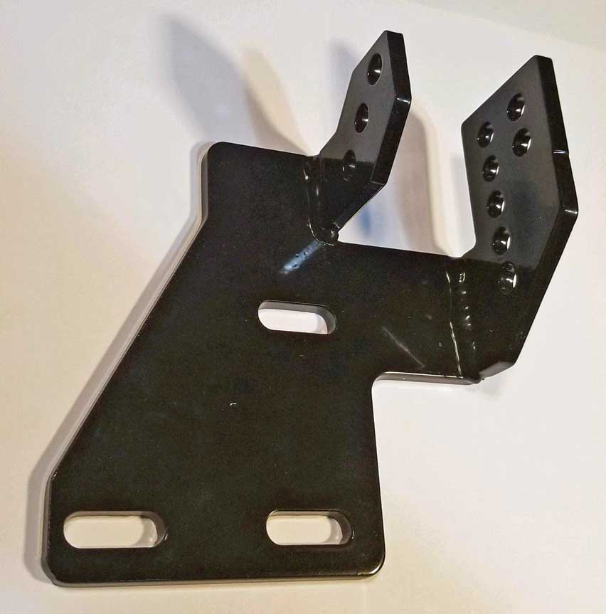
240 Alternator Idler Pulley Bracket for 240 red block B21/B23/B230 for use with a high-performance alternator: CLICK HERE. |
https://www.youtube.com/watch?v=zfGm0gZhgCc And for those of you who might like to learn more of this stuff: 12 Volt DC Basics: http://www.billavista.com/tech/Articles/12V_DC_Basics/index.html The Alternator Bible: http://www.billavista.com/tech/Articles/Alternator_Bible/index.html |
|
https://www.prancingmoose.com/AdjustableVoltage.html#failure This is where you should begin if you're having charging system failure issues. If you are merely a victim of a typical weak under-charging Bosch alternator, you can stay here and have a look below. |
|
| Here's an interesting video of the complete restoration of an old
Bosch external fan alternator. https://www.youtube.com/watch?v=eLgjyJBvYs4 |
|
|
|
|
| And
here's one that's show you a pretty good partial rebuild of a 1988 Volvo external fan alternator. https://www.youtube.com/watch?v=6o_OrF2S_UA |
|
|
|
|
| How about a video showing how to remove your 240 Alternator? https://www.youtube.com/watch?v=A72pWPYm8yo |
|
| Improving the Charge with a BIGGER/BETTER Alternator |
In stock form, that tiny 55A alternator was barely adequate from the beginning. Like most small Bosch alternators, it suffered from a significant voltage drop when a moderate load was placed on it, especially at idle (although raising the idle to about 1000 rpm did help). And it also suffered from an even larger voltage drop when it got hot (and of course it sits next to the turbo). 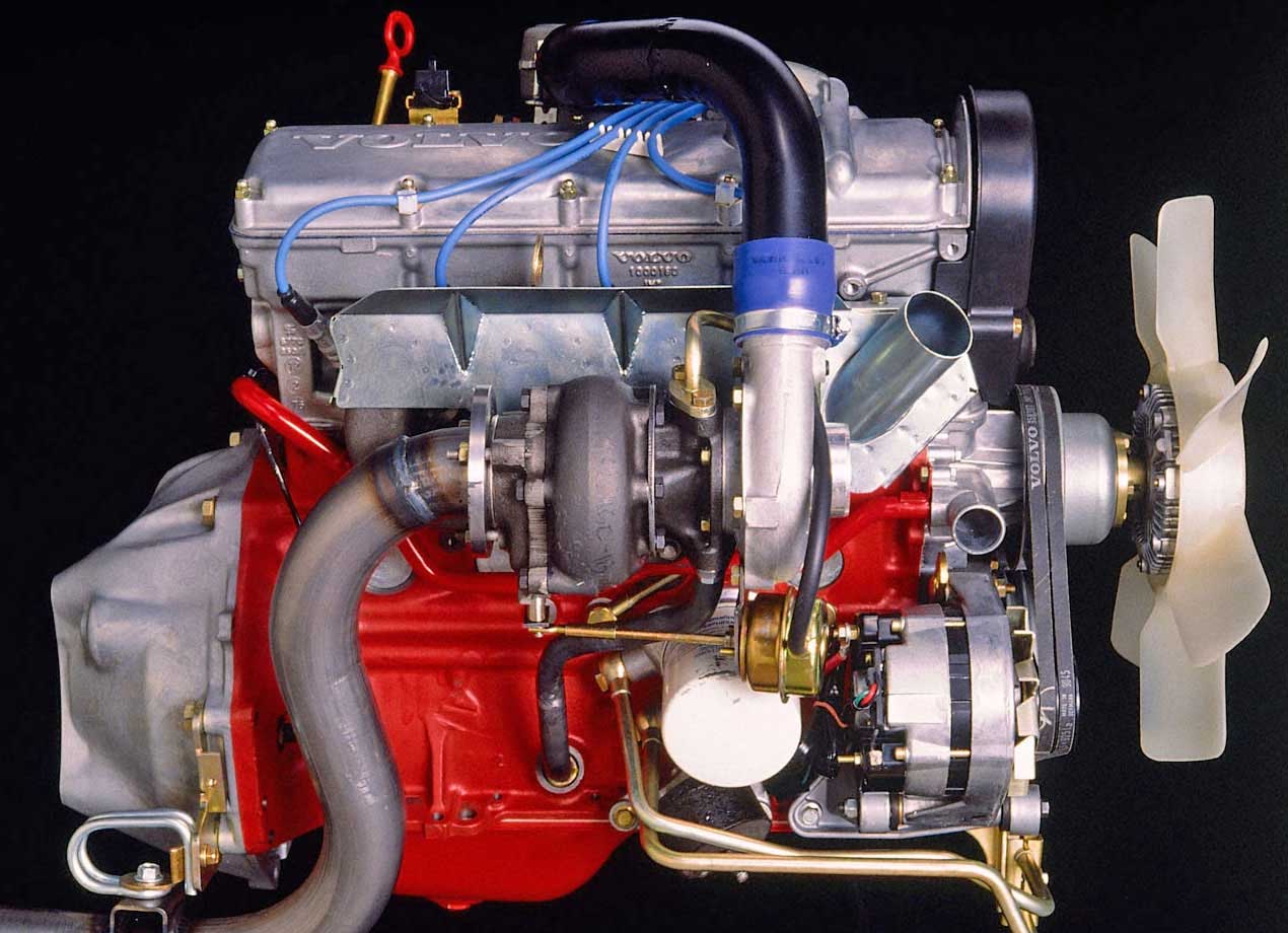
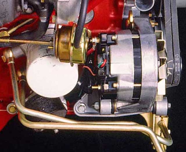 The Volvo B21 (red block) engine was not originally designed to have a turbocharger when it was designed in the early 1970s. The turbocharger was added much later. I guess the Volvo engineers did the best they could. Options are few if you have a flame thrower next to your alternator, unless you want to move the flame thrower or move the alternator. They did neither.
|
|
WHAT HAVE OTHER CAR MAKERS DONE TO ADDRESS A HOT ALTERNATOR PROBLEM?
This 4 cylinder engine is similar to the Volvo engine in that the intake manifold is on the LEFT and the exhaust manifold is on the RIGHT. Unlike Volvo, the Porsche engineers found NO ROOM on the exhaust side to add a turbo. Instead, they ran a pipe from the exhaust manifold, UNDER THE ENGINE, all the way to the intake side and put the turbo under the intake manifold just a few inches behind the alternator! Crazy stuff. 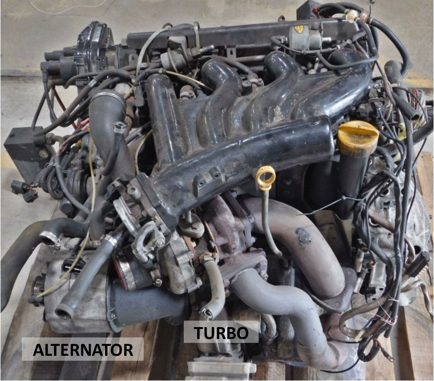 You can feel fortunate there were no German engineers working on the Volvo turbo engine design. 
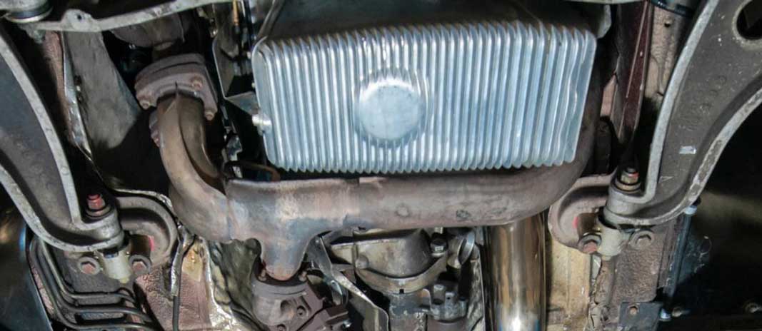
I had a discussion with a Porsche 944 Turbo owner about heat-related voltage drops. Porsche engineers did some extra work to try reducing the heat by adding a LARGE AIR DUCT to bring fresh air into the back of the alternator. This likely helped during highway speeds, but heat was still always a big problem. I don't know if Volvo engineers thought about this, but they would have had a difficult time doing something similar, unless they moved the OIL FILTER first.  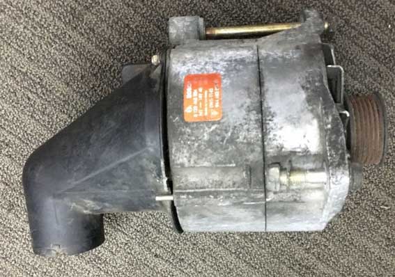 |
|
|
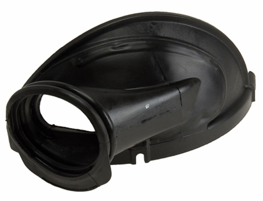 So if the 240 oil filter was to be re-located, maybe there could be room for something like this low-profile cooling shroud. This shroud is Porsche PN 96410640302. I have not tried doing anything like this. If you're inspired to try it, please let me know. |
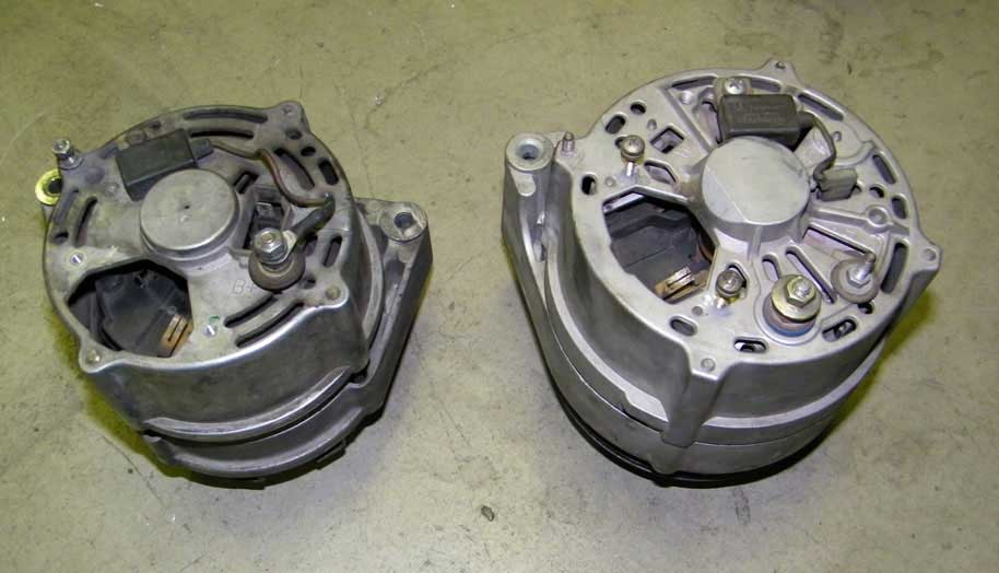

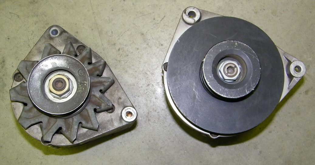 The above photos show a size comparison between a Bosch 55 amp (240 Turbo) and a Bosch 100 amp (740).
|
| 140 Amp Bosch Alternator |
Wes B. sent me a photo of his alternator, which he installed in his 240. It's a Bosch 140 amp Volvo unit he bought from Ebay seller BNR Parts ebay.com/bnrparts. He has reported that it's performing well and it maintains a hot idle at 14.2 volts. |
| Volvo 240 Accessory Belt Sizes |
|
 |
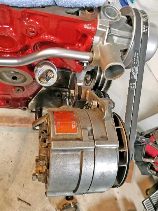
 THESE PICS are from some other 240, not mine, but it shows how TIGHT THAT SPACE is for the oil pressure sender when a big Bosch alternator is mounted. |
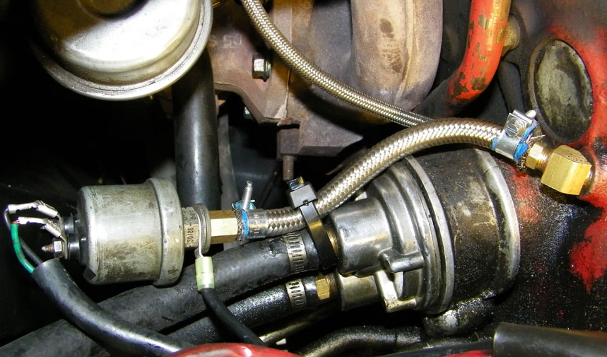 Ultimately, I dealt with the cramped space a bit differently as you can see in this image above. I mounted a "remote sender" after I had some bad experiences with other options, such as trying some adapter fittings which kept cracking from vibration. There's a longer story to this, but the short version is that this remote method actually worked very well for many years.
|
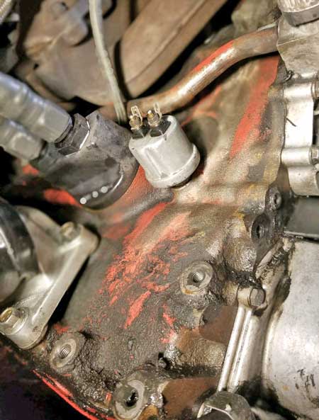
If you can find enough room, the ultimate position for this sender is
shown BELOW, WITHOUT ANY BRASS ELBOW or ADAPTER. This would require a way to move the alternator EVEN
FURTHER away from the engine.
|
A longer belt in this situation means the belt is going to hit that bracket. So the longest belt in this situation is probably going to be somewhere close to the 10 x 950 mm I used. That belt is about 25 mm longer than factory. 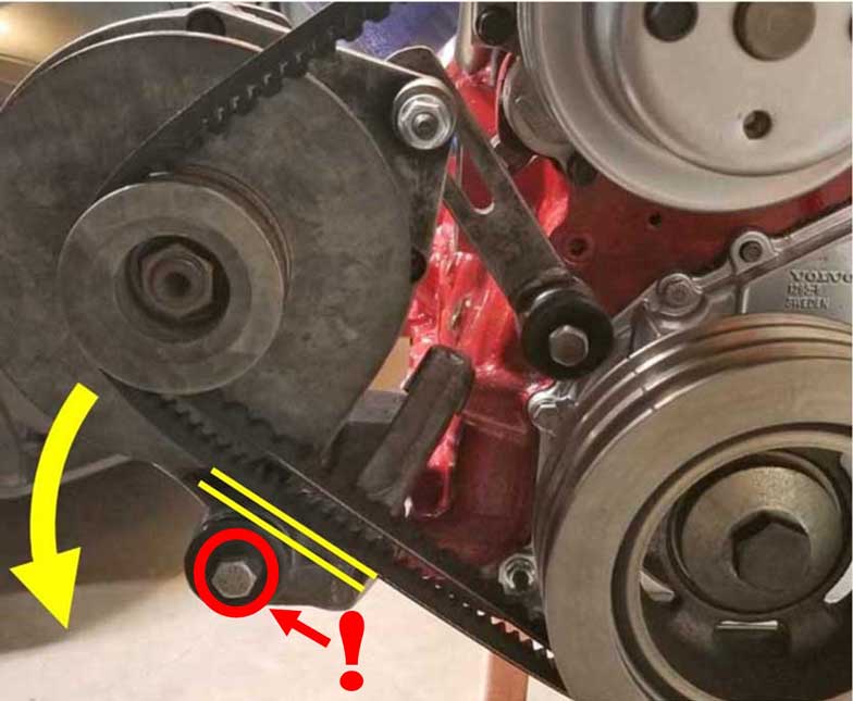
|
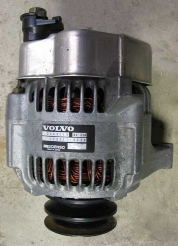
| Ok then. What about a DENSO? |
It's physically smaller than the above 100 amp Bosch. These Densos can usually be found in 80 or 100 amp capacity. They perform pretty much the same as a large Bosch alternator at idle. The most positive benefit is that they do fit better. There is more room for the oil pressure sender with this more compact alternator. 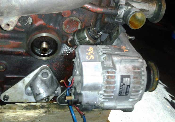
Denso alternators found in Volvos are usually either 80 Amp or 100 Amp. They look similar to each other, but you'll notice the 80 Amp units have a SMALL 6 mm lug for the fat red cable. 100 Amp units will have a LARGER 8 mm lug. 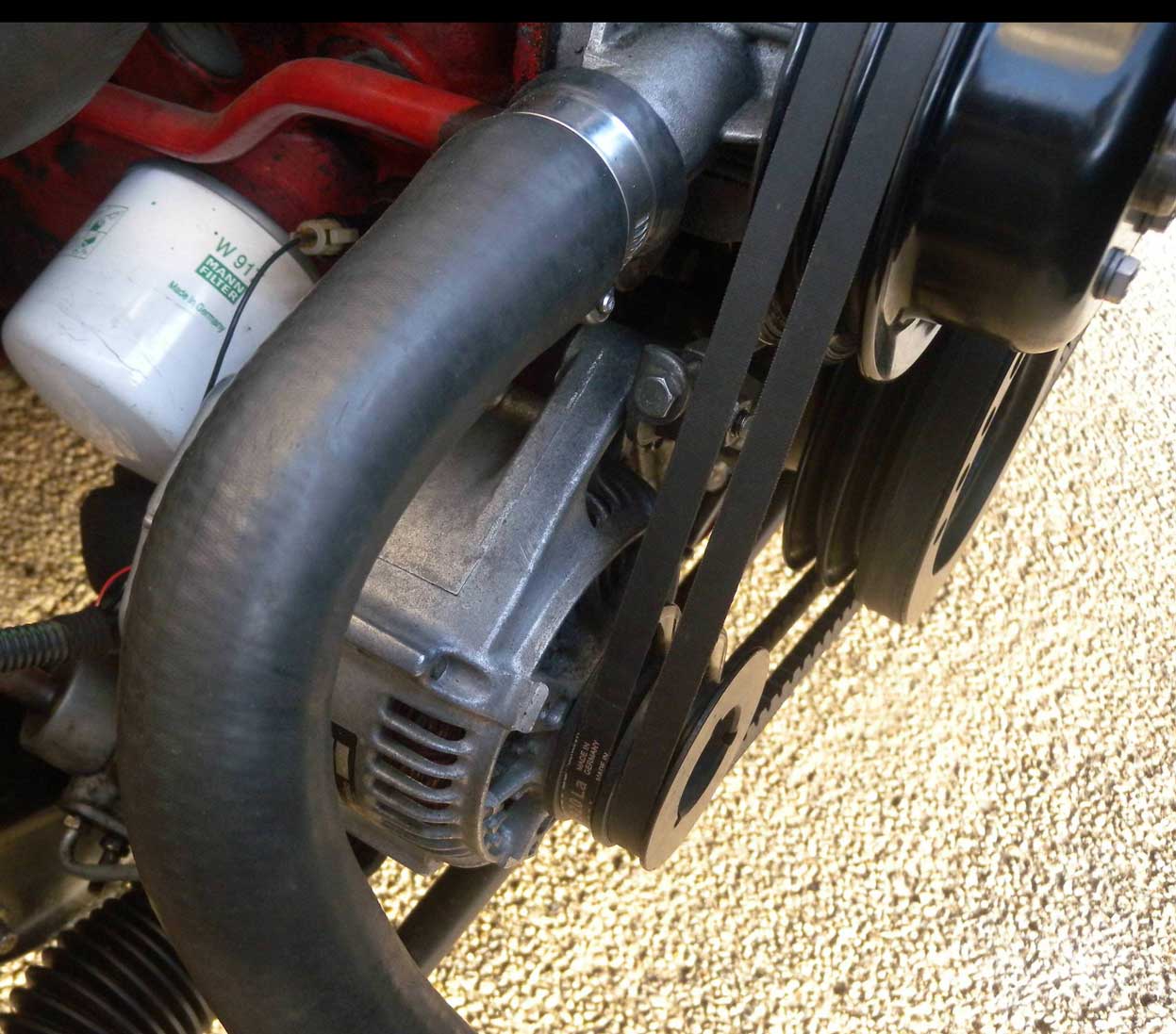
 |
And a discussion thread on Servicing a Denso Alternator: https://forums.turbobricks.com/t=349853 |
| INCREASING THE VOLTAGE IN A DENSO |
What about increasing voltage output for a Denso alternator like this?
It's not something I have tried personally, but there now seems to be
some interesting videos on this subject. Here's one where the
author increased output from 14 volts to 14.7 volts. The video is not in English, but following along is pretty easy.
|
|
| INCREASING THE VOLTAGE IN A BOSCH |
| This is a video about using diodes to increase voltage in a later (internal fan) BOSCH alternator. It's
not something I have tried personally. I've never worked on a BOSCH alternator
like this one, so I would consider this EXPERIMENTAL. Make sure you read the
video description so you have a good understanding before you burn your
car to the ground. VIDEO DESCRIPTION: 120A Bosch alternator modified to 15.3v. A simple diode mod to give 15.3v instead of the factory 14.5v when charging a single lead acid battery (test only). PLEASE NOTE: This is merely a proof of concept. The diode used in this video is only 3A rated and not enough on it's own for the field current at max load. After the video once fitted back to the engine, I swapped the diodes out to 2 parallel diodes in series (4x 3A diodes in total). This bumped the voltage up to about 15.8v at the alternator. Expected field current is approx. 6-8A max, so a single 3A diode could get very hot and blow quite quickly under heavy load. I must also mention any modification you do to your alternator or vehicle is done so at your own risk and I am not responsible for the result.
|
|
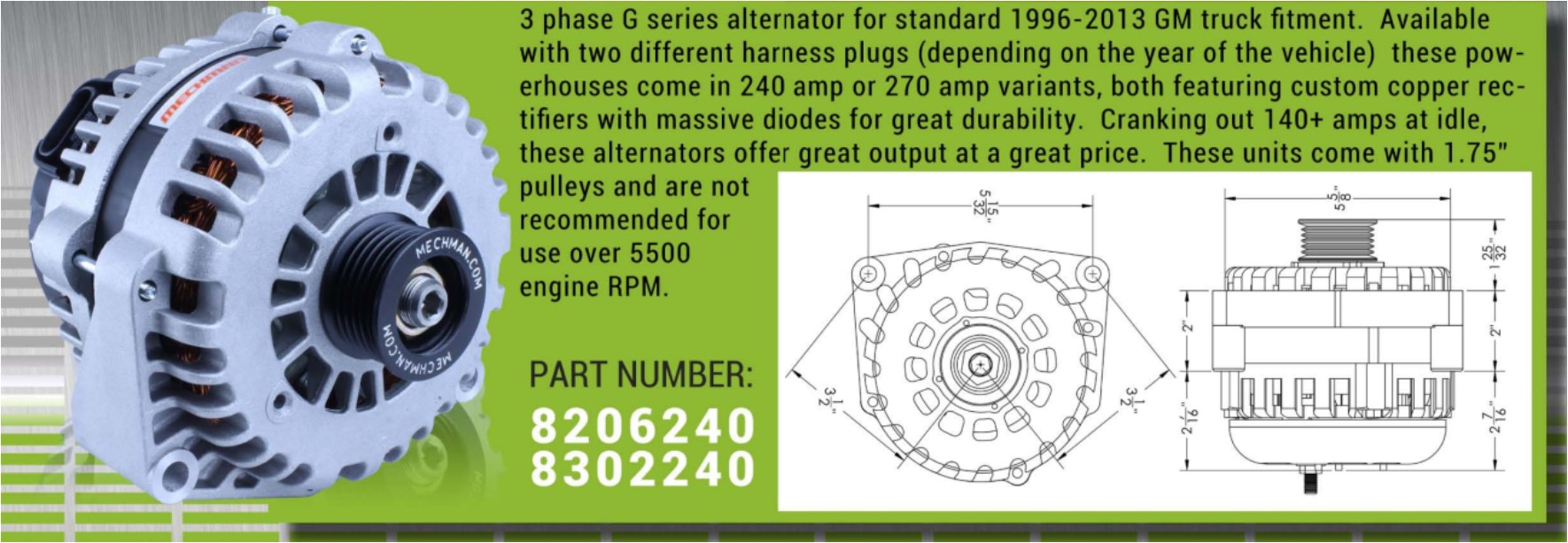
| Introduction of the Mechman Alternator #1 |
|
|
Back in 2010 I finally gave up on trying to make a
100 amp
Volvo Bosch alternator work to my satisfaction. Clearly, it was not going to cut it.
The biggest downfall for me was how it charged at IDLE when UNDER LOAD and HOT. When running the air conditioning (with a big electric primary puller fan and a condenser fan), voltage was suffering badly at idle and it became much worse after the alternator started getting HOT. I had begun using a big Ford electric puller fan, first trying a Ford T-bird fan from a salvage yard. I eventually changed to a Lincoln Mark VIII (Mark 8) fan. A Mark VIII can pull up to 40 amps at full speed, but full speed isn't really needed very often. But even a raised idle speed of about 1000 rpm couldn't bring voltage up enough for my happiness.
I then talked with Mechman and I told them about my low idle voltage. I was assured that a custom unit they would send me would improve voltage at idle by offering more amps at idle. Mechman didn't really have a high-performance Volvo-specific alternator, so they custom tailored a GM Delco style alternator to fit a Volvo. Skipping ahead: The 2010 Mechman alternator did improve charging at idle and overall output was much better, but it STILL suffered from an annoying voltage drop when it got hot. The voltage drop was not as bad as the Bosch though, but I still had to resort to keeping my idle up a bit higher than normal to keep charging voltage from dropping off below 13V when everything was on. I began thinking there might NEVER be a real solution for a 240 Turbo with the alternator on the hot exhaust side and I thought I might have to eventually move the alternator to the other side of the engine like on the Volvo 740.
BOSCH ALTERNATOR VOLTAGE DROPS With the BOSCH 100 amp alternator, the voltage drop between COLD and HOT with a heavy load at IDLE was: 14.4 volts COLD to 12.4 volts HOT. A FULL 2 VOLT DROP! Unacceptable. Also this situation was forcing me to set the idle speed higher than it should be to help keep voltage from going through the floor. Here's a temperature reading from my exhaust manifold (AT IDLE) a short distance from my alternator. 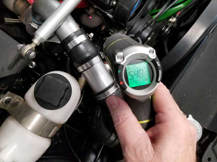
|
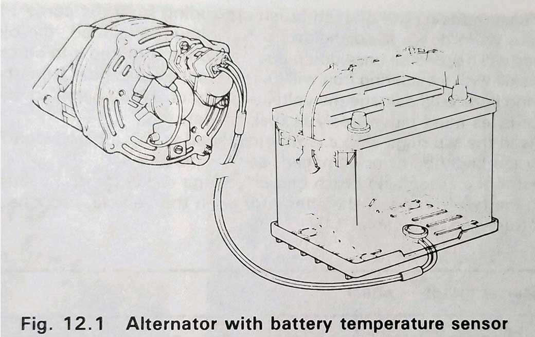
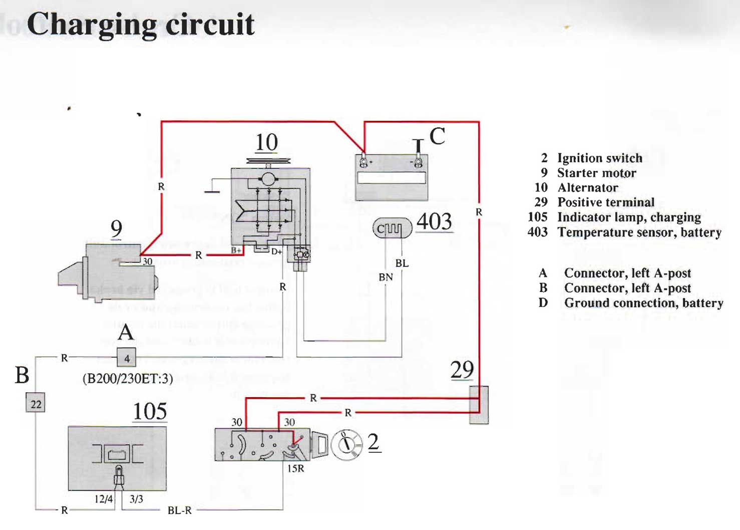
The reason is that the design of an automotive alternator, specifically the design and efficiency of the copper windings, has a direct effect on the deterioration of current output as temperatures increase. This is partly due to increased resistance in the copper windings as temperatures increase. This deterioration could be corrected by design, however increased current output always increases internal temperatures even more. Heat is the biggest enemy to alternator long life, so alternator engineers needed to compromise and they have simply prioritized the designs of alternators to have the best chances of surviving a WARRANTY PERIOD. Specifically allowing an alternator to reduce output when it gets hot is the answer to that compromise. So there's really not much else you can do with a standard Bosch automotive alternator if it's getting hot and dropping voltage. Volvo did add a thin heat shield for the 240 Turbo. It probably helped slightly. This is not as much of a problem in cars where the alternator is on the opposite side from the exhaust, like in the Volvo 740 or 940. Isn't there a temperature sensor in an alternator that helps to regulate current output? With regard to old Bosch alternators that we find in our old Volvos, the answer is NO. There is no temperature regulation in the alternator or in the voltage regulator (except of course the common deterioration of efficiency with higher temps as mentioned above). There are more modern alternators made now, which have internal temperature sensors, but that never existed for the old Bosch units in a 240 or 740. What about the battery temperature sensor found in some Volvo 740s? From 1985-87 some Volvo 740s came with a special voltage regulator, which was connected to a temperature sensor mounted under the battery. See the images below. This sensor was there to measure the battery temperature, not the alternator temperature. Additionally, this system did not compensate for high under-hood temps. It was designed to elevate alternator voltage 0.5 volt when it detected extreme cold ambient temps. 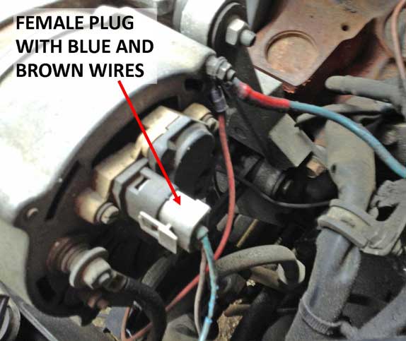
 |
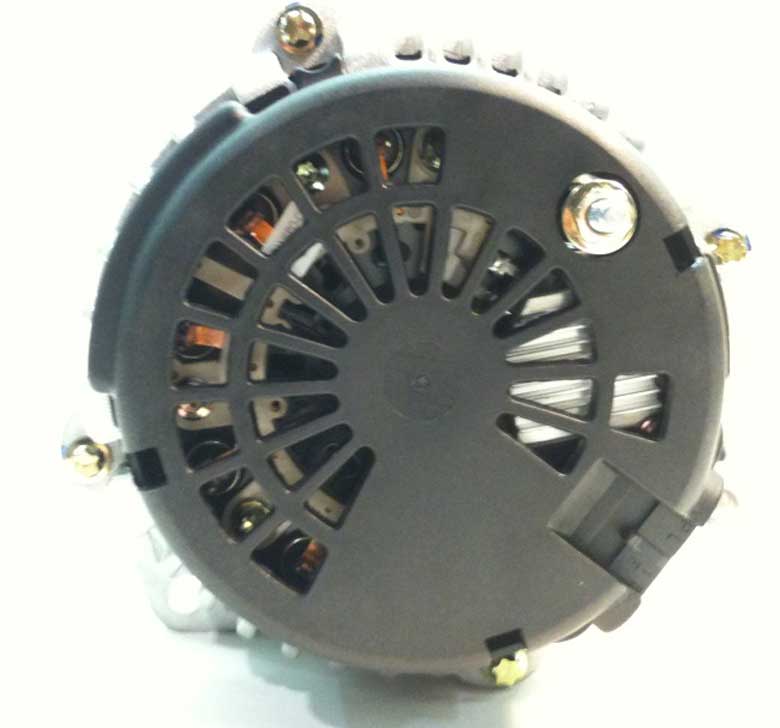
| FIRST GM MECHMAN MORE DETAILS (2010) |
| Here's the
Mechman alternator from 2010 compared to the Bosch 100 amp I was using up to that time. The Mechman used a large case GM Delco style housing. This particular alternator had its case slightly modified by Mechman to fit better in the factory Volvo mounting location (while also using a few spacers). I was told this Mechman unit was created as a one-off 170 amp alternator based on the Delco AD230 (which was reportedly in a 1996-2013 GM truck). NOTE: An alternator like this is used in cars which DO NOT have an ECM or computer controlling the alternator charge output. This unit from Mechman had a little custom machining to its case at a mounting location so it would bolt up similar to the Volvo Bosch alternator. More about the machining modifications Mechman did can be found HERE. 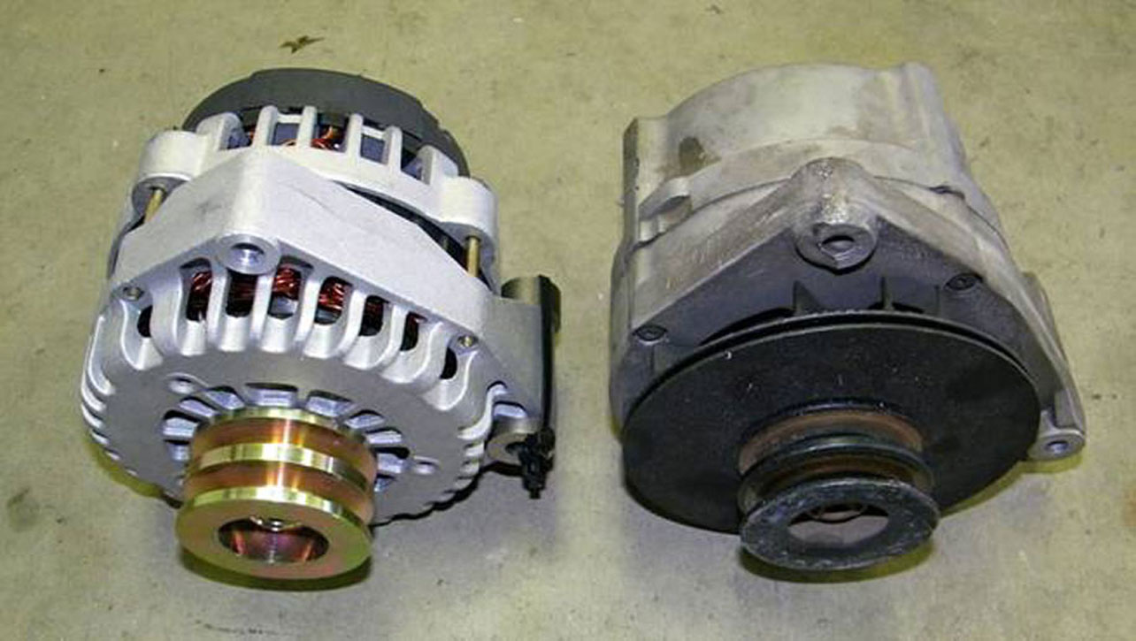
Similar Volvo conversions have been done using GM AD244 and GM DR44 late model truck alternators. The reported benefit is better output at idle, which is something the old Volvo Bosch unit don't do well. 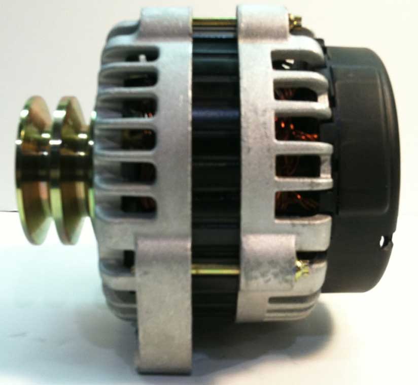
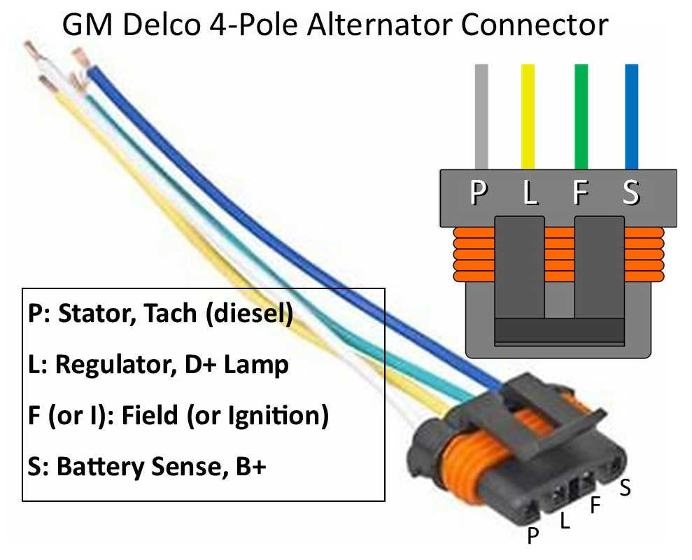 This connector can be found fully assembled with wire pigtails as PN 110-12046. If you need the connector housing only or the terminals and seals separately, search for: Metri-Pack 4-Way connector, Aptiv (Delphi) PN 12186568. Female terminal 17-20 AWG, Aptiv (Delphi) PN 12048074. Wire Seal Aptiv (Delphi) PN 15324976. Sealing Plug Aptiv (Delphi) PN 12059168. 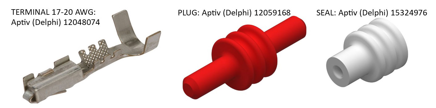 More info: www.dirtydingo.com/ID=108 |
 The belt size I typically used for the Bosch 100a was 10 x 925 mm or 10 x 950 mm. I found that if I could swing this Mechman slightly further from the engine, I could eventually fit a 10 x 965 mm. The limiting factor was always the lower part of the alternator bracket where you can see the belt getting close. |
| GROUND CABLE When Using a GM Alternator |

The best charging results with this new (2010 Mechman) alternator came after I added a dedicated 4 GAUGE ground cable and positive cable DIRECTLY from the alternator to the battery. You can see the results of numerous tests in the above mentioned installation thread. I still experienced a pretty significant COLD-to-HOT VOLTAGE DROP using this alternator, but ultimately adding these cables provided the best result so far for any alternator I had tried up to this time. |
| Using enhanced (LARGER) POSITIVE and NEGATIVE Cables. |
My first cable version used large, fat normal strand cable. The vibration and flexing of the fat power cable at the alternator eventually broke the cable at the alternator lug after a number of years and many miles, leaving me stranded and calling for a tow truck. Plan ahead and get better cable. 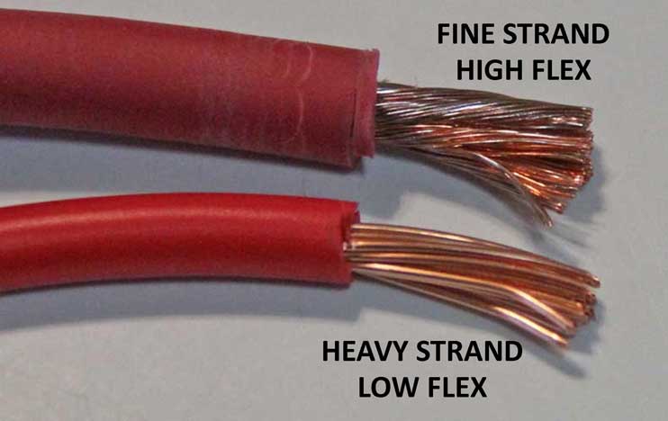
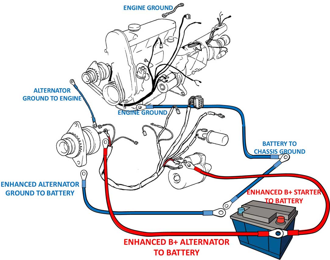 This illustration ABOVE will give you an understanding of the enhanced power and grounds that are recommended with a high-amp alternator. You might consult the manufacturer of your alternator for a cable size recommendation, but be prepared to be told to make them very BIG. I made this illustration above to show the big dedicated cables (POWER AND GROUND) going directly from the BETTER TO ALTERNATOR and a big cable from the BATTERY TO STARTER. The factory used a cable going between the alternator and the starter. This become unnecessary. Using a cable there was convenient for the Volvo factory, but it's better to ALWAYS use cables directly from the battery to the component. |
|
|
| |
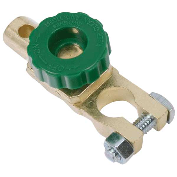 <<<
WARNING NOTE: I don't recommend using one
of these inexpensive disconnect devices on your battery
when using a high output alternator like this.
I had one of these on my
negative battery terminal back in 2010. After
installing the Mechman I began experiencing
some strange intermittent momentary voltage
drops when the alternator was under load,
such as when the AC was on. It took a
while to figure it out and it's detailed in
the Turbobricks thread mentioned above. It turned out
that this disconnect knob was creating higher resistance in the ground cable
circuit and the Mechman was sensitive to
it. I removed this devise so that my battery ground was solidly connected. <<<
WARNING NOTE: I don't recommend using one
of these inexpensive disconnect devices on your battery
when using a high output alternator like this.
I had one of these on my
negative battery terminal back in 2010. After
installing the Mechman I began experiencing
some strange intermittent momentary voltage
drops when the alternator was under load,
such as when the AC was on. It took a
while to figure it out and it's detailed in
the Turbobricks thread mentioned above. It turned out
that this disconnect knob was creating higher resistance in the ground cable
circuit and the Mechman was sensitive to
it. I removed this devise so that my battery ground was solidly connected. |
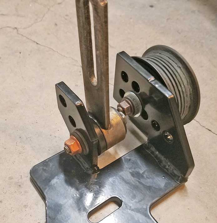
| Dealing with BELT SLIP |
|
| Have a good look at the belts wrapping around this pulley. There's just a little more than
90 degrees of belt wrap. The actual belt-to- pulley contact patch is pretty small. But that's how a 240 is designed. This is not very good and it's why the designers added DUAL BELTS. 
This
was not really a problem back when the weaker 55 amp original Bosch
alternator was there, but it became intolerable with a high
output alternator.
I found that I needed to tighten the
alternator belts much more and then they usually needed more tightening
later as they began to wear. I was putting a LOT of stress on my belts. That can cause problems.
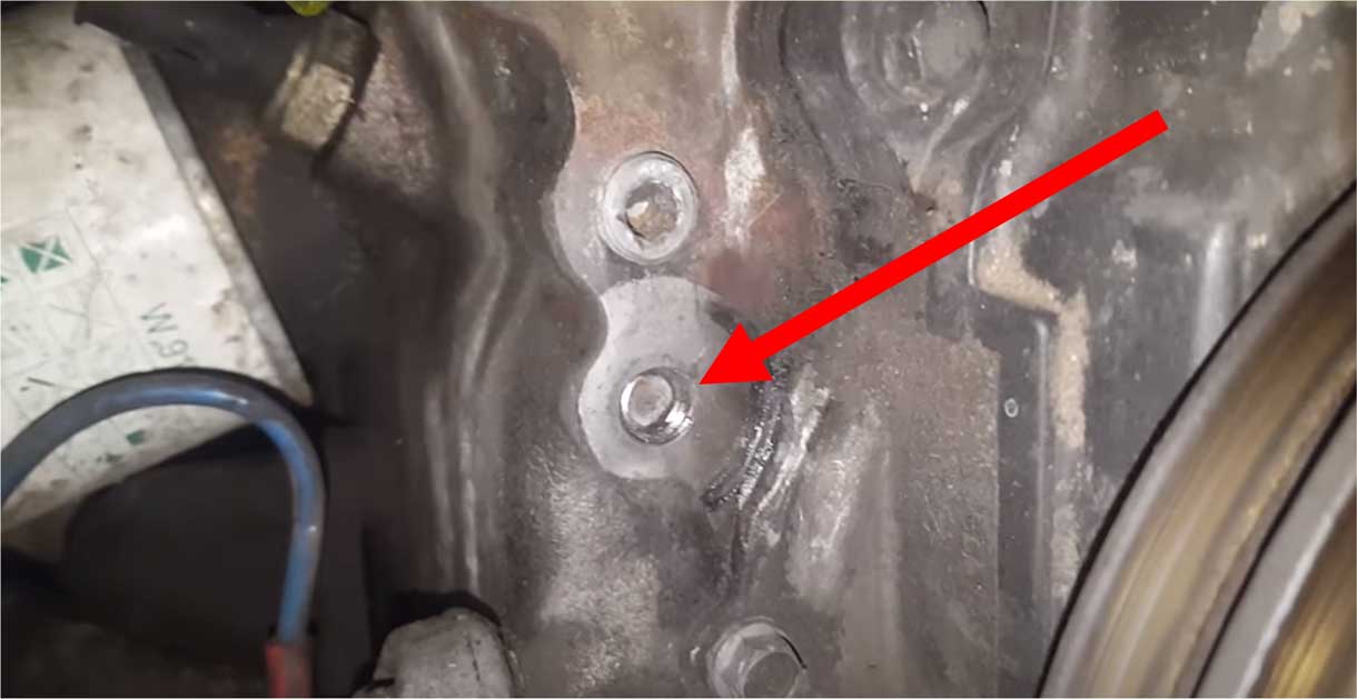
That bolt on the front of the block for the adjusting bracket has been known to break off (it happened to ME). I've also heard of a few people with broken water pump pulleys (see thread here: https://www.forums.turbobricks.com/t=323223). Over-tightening a V-belt is just plain BAD. It can also prematurely wear water pump bearings and generally your belts don't last as long as they should. They just wear faster and then they begin slipping again sooner. |
|
| MORE ON THE BROKEN BOLT ISSUE WILL CONTINUE LATER IN THIS PAGE. |
|
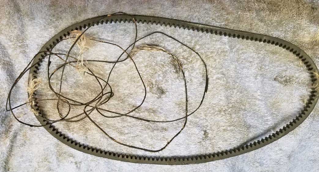 It failed after about 300 miles of use because it was adjusted too tight. The belt didn't actually break, but it did jump off the pulleys after breaking those reinforcing cords. |
|
|
|
|
That
long corded string stuff above was the embedded cord in the top-side of the
belt. The cord separated from the belt (or maybe snapped from too
much tension) and then eventually unraveled.
The belt eventually came off the pulleys and I found it sitting in my
belly pan. Most of that corded material ended up wrapped around my AC
pulley. Once that
corded part separated, the belt lost the ability to stay tight. After losing that corded material, the
belt became more like a big, soft, stretchy rubber band. 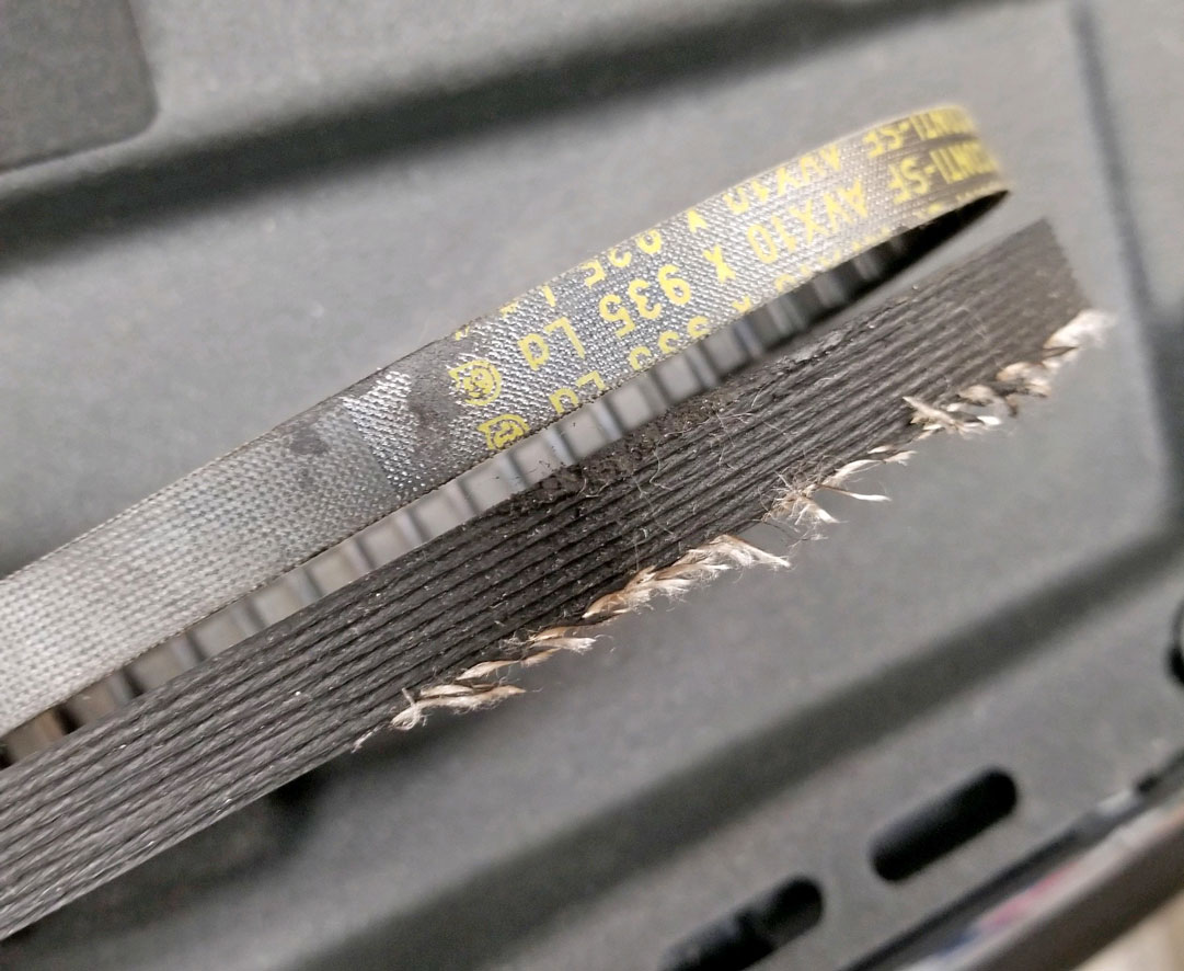 |
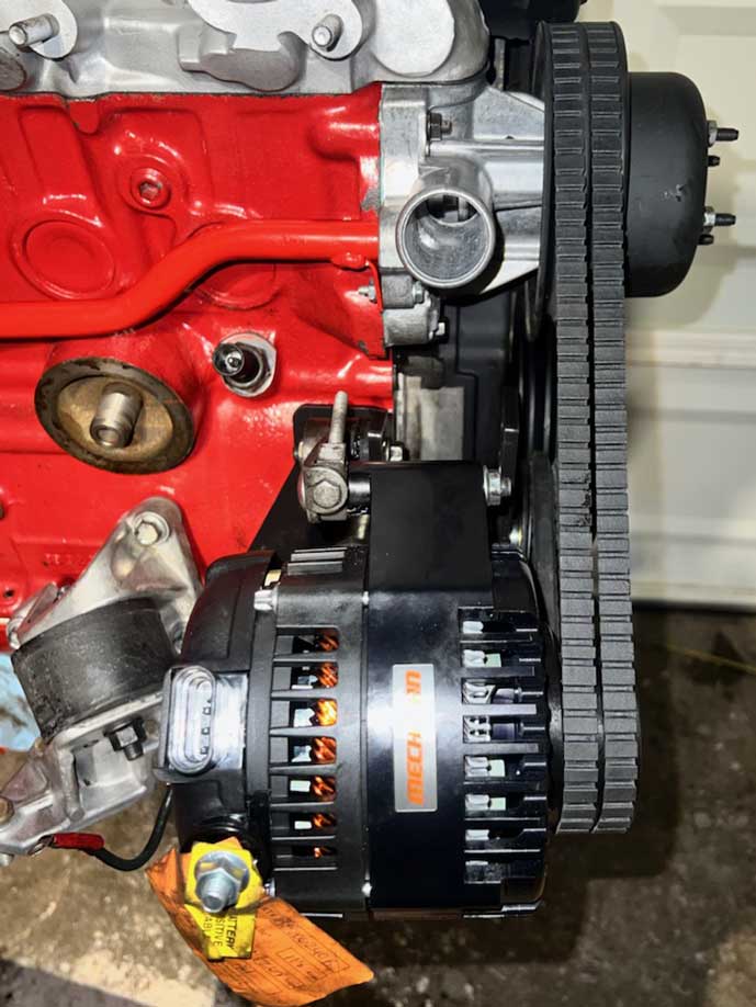
| MECHMAN #2 |
|
|
||
| Wiring a GM Mechman |
Increasing Voltage in a GM Alternator |
|
| PLFS 4-Wire Plug Info |
GM Voltage Regulator |
|
This alternator came with a 170 amp 6 phase HAIRPIN STATOR. According to the literature a bit further below, it's based on a GM Delco CS130D (original to a 1998-2002 GM F-body, i.e.: Camaro). NOTE: An alternator like this is used in cars which DO NOT have an ECM or computer controlling the alternator charge output. This Mechman part number was B8206170M (PN B8206 with 170 amps). 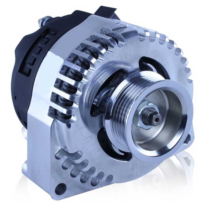

|
|
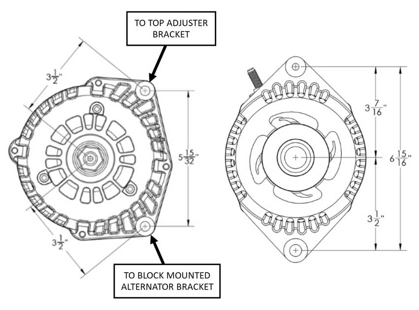
| The alternator Mechman provided for me
was custom prepared by them for a VOLVO. This means they did some MINOR MACHINING to the case so it would easily bolt up in the Volvo red block mounting location similar to a normal Volvo Bosch alternator. And of course it also got a double V-belt pulley instead of a serpentine pulley, since the 240 uses V-belts. More on the custom modifications that were done to create this alternator can be found HERE. |
So are the custom features really necessary? The answer is NO! There are great solutions to make a UNIVERSAL high-output alternator fit your Volvo. I have added info below that will help. CLICK HERE. |
|
| So, the 6-phase hairpin design looks pretty cool. . . . but does it actually perform better? YES IT DOES. Keep reading below. |
 More info below on the P-L-F-S connector. . Here are a few ways to connect an alternator like this. You've undoubtedly heard of 1-wire alternators. Forget what you've heard. This is NOT a 1-wire alternator. A true 1-wire alternator is considered self-exciting and doesn't require an external circuit source to excite charging. The GM CS130D requires an external source to excite it (similar to a Volvo Bosch). In most OEM systems, this excite circuit is the wire to the dash battery warning lamp, like the Volvo Bosch. In this example below, a resistor is used instead of a lamp. Note: P-L-F-S plug pin designations are sometimes called P-L-I-S. 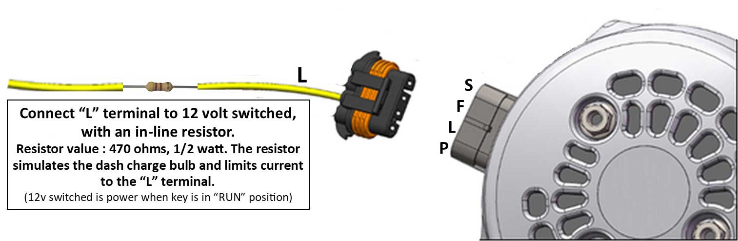  Resistor. 470 Ohm 1/2 W Carbon Film Single Resistor. www.amazon.com/WWNKYZX7ES9QZMTDZ693 The polarity for a resistor is not specific. A resistor can point either direction. If you're familiar with the old Bosch alternator, it used the red D+ wire from the dash charge warning lamp to excite the charging. The GM CS130D is not very different. This method above is pretty standard for this type of alternator, which uses this the P-L-F-S plug. With this method above the “L” (Lamp) terminal is connected to switched 12v, with a resistor in-line to reduce current to the regulator. The resistor will offer a similar effect as a warning bulb, except with this method you will not have a dash warning lamp that will illuminate if the alternator fails. Either way, the resistor is important. Many on-line sources say that if you do not use a resistor on this circuit, you may eventually burn up the voltage regulator. The 12 volt switched source needs to be powered when the key is in the "RUN" position. This will activate the alternator when the engine begins running. It must be a switched circuit, because if a constant 12v circuit was connected, it would eventually drain your battery after the engine was shut off. ALTERNATIVE using TWO Excite Circuits 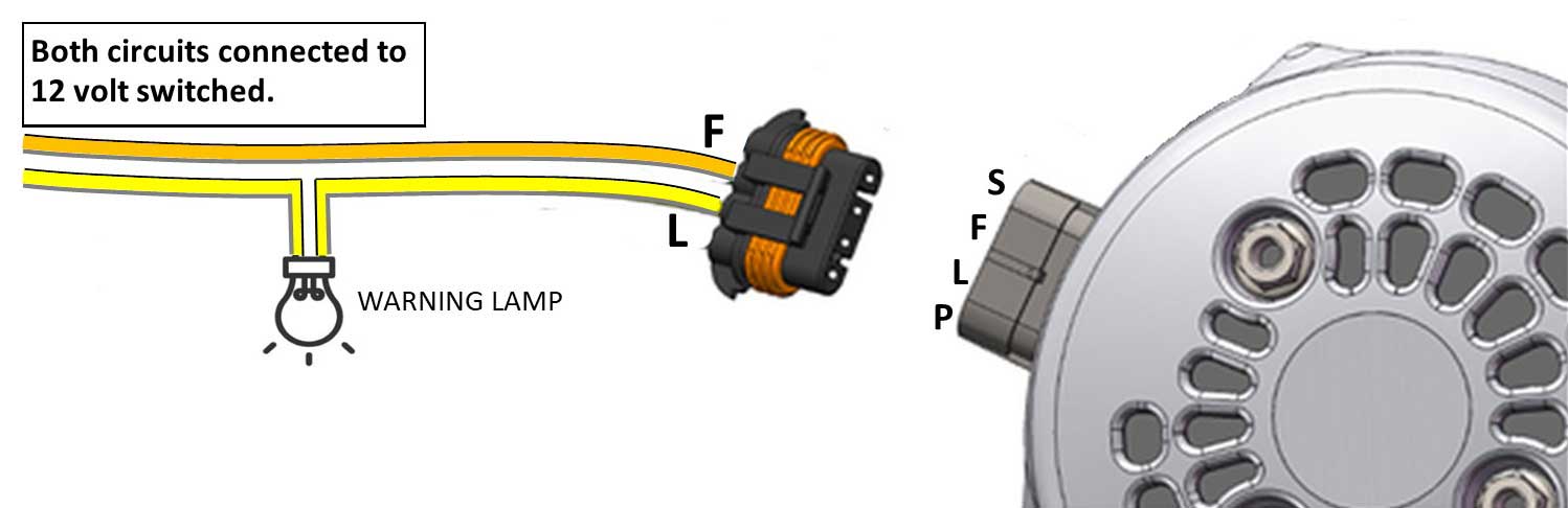 An alternate method of exciting the alternator is shown above. This method offers two redundant ways to excite the alternator. Plus it offers an opportunity to have a normal dash warning lamp if you want one. The lamp used in a dash lamp is normally a very low wattage incandescent bulb (1 or 2 watts). The bulb will offer a small amount of resistance, which will serve protect the regulator in the same way as the resistor method above. The alternator doesn't need very much resistance to excite and a 1 or 2 watt bulb is perfect. Some sources say the minimum trigger to excite might be as low as 1/4 watt. The only downside to using a bulb to excite the alternator is if it burned out, the alternator may stop charging without warning. Fortunately, this above method also offers a redundant way to excite using the 'F' terminal. The "F: terminal is also connected to switched 12v. No resistor should be used with the 'F' terminal wire. More info: www.dirtydingo.com/shop/ID=108 .VIDEO: Activation of GM style alternator with P-L-F-S plug. Here's a video that demonstrates the use of the above 470 Ohm resistor INSTEAD of a bulb. https://www.youtube.com/watch?v=a3pp448t0U4 Resistor. 470 Ohm 1/2 W Carbon Film Single Resistor. www.amazon.com/dp/WWNKYZX7ES9QZMTDZ693 The polarity for a resistor is not specific. A resistor can point either direction. VIDEO: Here's a tricky method designed to BUMP UP VOLTAGE in any GM style alternator that has an 'S' (Sense) terminal. This method may work for any other alternator which uses an S terminal. This method uses diodes. Mods like this are at your own risk. https://www.youtube.com/watch?v=qLX-RBcsNrU In the above video he is using the following resistor and diode below: Resistor connected to the "L" wire: 470 Ohm 1/2 W Carbon Film Single Resistor. www.amazon.com/dp/B07QYRRX3L The polarity for a resistor is not important. It can point either direction.  Optional DIODE connected to the "S" wire: 1N5404 Rectifier Diode 3 amp 400V. www.amazon.com/BOJACK-Rectifier The polarity for a diode is important. The silver band needs to point TOWARD the ALTERNATOR. Here's another video below discussing the above 1N5404 3 amp Diode connected to the 'S' wire where an increase of about 0.3 volts per 3 amp diode is demonstrated (results can vary). https://www.youtube.com/watch?v=MRoJMv-yMSY Alternately you may use one or more 1N40001 - 1N4007 1 amp Diodes instead of a 3 amp if you feel like experimenting for different voltage results. 1 amp Diodes are featured in the next video below. POTENTIOMETER METHOD TO INCREASE or ADJUST VOLTAGE in a GM Alternator Here's another method designed to bump up voltage output in an alternator with an 'S' (Sense) terminal. This method uses a 5k Ohm POTENTIOMETER and optional 1 amp diodes. NOTE: Mods like this are at your own risk. https://www.youtube.com/watch?v=QEIpHnuj6sc This video above is very brief and explains things rather quickly. I made a diagram below that will help. The 1 amp diodes are optional. He explains that these diodes are in place to offer a default voltage setting that will be ABOVE the normal setting, which only comes into use in case the potentiometer circuit fails. So you could try out one, two or three diodes there to see what that setting would be.  At the end of the above video he says, "This is effectively a $5 external voltage knob, not $80." I think the $80 knob he is referring to is a 5k Ohm potentiometer box that is a ready to use device and sold as the Brand X Voltage Control Knob: https://brand-x-electrical.com/ . If you're looking at ready-made control knobs, that might be a solution. Or you could consider one from Coventry Car Audio, which offers a control knob with a voltage display: https://www.coventrycaraudio.com/. If you use one of these ready-made devices, you'll see in their instructions that you can use an optional relay. I DEFINITELY recommend using that relay. 4-POLE ALTERNATOR PLUG INFORMATION This plug connects to the regulator and would be typically found in a 1998-2002 GM F-body (Camaro), 2004-2005 Buick or Pontiac, and 2001-2006 Cadillac. Fits alternator part numbers: Denso 104210-3060, 104210-3070, 104210-3300, 104210-4540; GM 15145637, 25697765, 25697766, 25758348, 25759776, 84009369. Note: The P-L-F-S pin designations below are also sometimes called P-L-I-S. This connector can be found fully assembled with wire pigtails as PN 110-12046. If you need the connector housing only or the terminals and seals separately, search for: Metri-Pack 4-Way connector, Aptiv (Delphi) PN 12186568. Female terminal 17-20 AWG, Aptiv (Delphi) PN 12048074. Wire Seal Aptiv (Delphi) PN 15324976. Sealing Plug Aptiv (Delphi) PN 12059168. More info: www.dirtydingo.com/ID=108 DELCO VOLTAGE REGULATOR 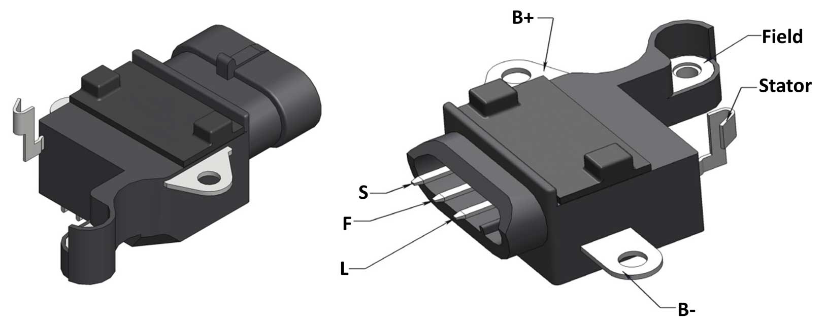 If the voltage regulator ever needs to be replaced in this CS130D type Delco alternator, I thought I would add that info here, just in case it becomes useful to you (or me) in the future. 12 Volt, B-Circuit, S-F-L Terminals, 15.0 Voltage Set Point, w/ LRC For Denso Alternators. Part Numbers: Denso 126600-0030, 126600-0031, GL10031, 104210-330, 104210-454, Transpo IN6003. |
 Anyone can install a volt meter. I've installed many, but this is a bit DIFFERENT. THIS section will discuss my work in getting a really, really ACCURATE volt meter, after many years of NOT having a very accurate one. Working toward an extremely accurate volt meter might seem a bit obsessive, but if you've read this page, you can easily come to your own conclusion about THAT. If you've used the factory 240 VOLTS gauge, like I did for a while, you know it's NOT known for being precise and probably not very CONSISTENT either. The below info will detail how I did this project in my 240 and the results. I have some suggestions here, but this certainly is NOT the only way to do this kind of thing. I welcome your comments. Teaser - Spoiler You'll see more about this if you keep reading, but what I discovered got my attention. If you test voltage at the battery or in the dash when your car is idling with LITTLE OR NO LOAD, you'll generally see less voltage than what the alternator is actually putting out. Maybe only a few tenths of a volt less at the battery. A lot less if measured at the dash, possibly 3 to 5 tenths of a volt less at the dash with LITTLE OR NO LOAD. Then if you do the same test WITH A HIGH LOAD (such as with AC running), I have seen a voltage drop of up to 1.5 VOLTS LESS, even though the OUTPUT AT THE ALTERNATOR really did not change at all. My Volvo originally came with one of these VDO VOLTS gauges. It can help give you a general idea that things are charging or not charging, but you can't tell a whole lot more about your alternator performance.  |
 And THIS TIME I wanted to step up to a 4-DIGIT LED display (with 2-digits to the RIGHT of the decimal). Four digits for no reason other than preference.   |
Having a 4-digit meter isn't important. This guide works with any voltmeter. This 4-digit unit has three wires instead of two wires. You can see the meaning of that third wire in the diagram below. That's not a super important thing. You can see below I connected both power wires to the same place. 4-digit meters like this are a bit harder to find if you want one. You can try searching for 4-digit DC volt meter. Having 4-digits does NOT make this more accurate. What makes it accurate is a MORE DIRECT PATH from the alternator to the meter. A typical factory in-dash volt gauge doesn't have a very direct path at all. Not even close (see here about why that "path" is bad). The factory gauge will have a number of connections between the battery/alternator and the dash. So it suffers dramatically from voltage loss. This diagram below involves the GM 4-wire alternator I'm using. The Bosch diagram is further below. 
The POWER and GROUND PATH in this diagram above from the alternator to the volt meter is pretty DIRECT. The only thing I added in it's path is a standard mini RELAY. Without that relay, the alternator "S" Sense circuit in this GM type alternator would be active all the time when the car is off. Also the meter would be on all the time. That can drain the battery and it's kinda bad to do that. So the relay is there to activate things when the car is on and running and to shut it all off when the car is OFF. DIAGRAM for a Volvo BOSCH Alternator? Even easier. The relay is still used. A relay should be included or your meter will never shut off.  An ALTERNATE connection to the KEY IN Warning Chime can be made below. With this connection the only change will be the volt meter will activate when the key is inserted and will stay activated in all key positions until the key is removed. The reason for choosing this method would be if you want to see the battery voltage before you begin turning the key. 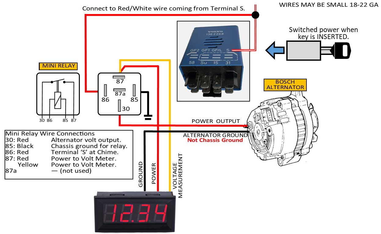 |
Here's an example of how COMPLICATED the PATH normally gets for a factory 240 volt gauge. Beginning at the battery, there's a wire going to a junction block on the inner fender. From there, another wire goes back to the firewall, into the under-dash area, terminating at a pole on the ignition key switch. This is where battery power is switched to ON for things in the dash that don't have full-time voltage. From the ignition switch, aother wire runs to the fuse panel. The circuit will then probably go through a fuse (possibly fuse 13), and then a new wire goes to a multi-pin plug near the instruments. From that plug a power wire is shared by several gauges. Meanwhile a lot of voltage drop has taken place. NOTE ABOUT CHASSIS GROUND: Using a normal chassis ground in the DASH is fine for most devices, but the same voltage problem can happen for a volt meter with a poor chassis ground. A chassis ground in your dash may not provide as clean a path as a DIRECT ground wire DIRECTLY from the battery or the alternator to the volt gauge. This is why I say it's important to take the power and ground for this meter directly from the alternator.. Is VOLTAGE DROP really such an important thing to eliminate? Take a few seconds and watch this ONE MINUTE video on Voltage Drop Testing. https://www.youtube.com/shorts/ORv0eh_aY2A |
My testing has suggested that volt meter readings can be more consistent when very little load is present, but when load increases, consistency changes, sometimes a lot. We know using power-hungry accessories will pull voltage down in most Volvo 240 systems, but does that always mean the battery or alternator output is being pulled down equally. My tests say NO. This type of inconsistency can fool your volt gauge into registering less voltage than your system has at your battery or alternator. Here are some photos showing the wiring to my GM type alternator. The first image below shows the PLFS plug on my Mechman alternator.  The next image below is an Amphenol AT connector for those same wires as they run from the alternator to the right fender. I added this connector for convenience so it's easier to disconnect when I need to remove my alternator.The wires below then go back to the firewall and into the dash. I have a detailed page HERE showing this Amphenol connector if you need to see more about it. These connectors are easy to work with and are waterproof. 
This image below is showing the new 4-digit meter installed at the base of my center console. Yes, it's reading 14.77 volts. That's actual alternator output for my Mechman.  COMPARING VOLT READINGS: If I test the voltage at the battery when idling, it generally reads about 1 or 2 tenths of a volt less than this alternator output. When measuring the voltage coming from the battery to the dash, which suffers from the most voltage drop, it can be 3 to 5 tenths of a volt less than alternator output when NO LOAD is present. A LOT worse, up to 1.5 VOLTS LESS, when there's a HIGH LOAD. So now with this new meter setup showing me the ACTUAL ALTERNATOR OUTPUT at all times, I can rest more comfortably on long trips knowing my alternator is nice and consistent. |
| MORE GM MECHMAN GENERAL INFO |
 The GM Mechman I'm using is this one above, PN B8206170M. The '170' in the PN is the amps. The 'M' is a machined finish. This style alternator is also available in 240 amps and in a BLACK finish, such as the PN B8206240B pictured below. 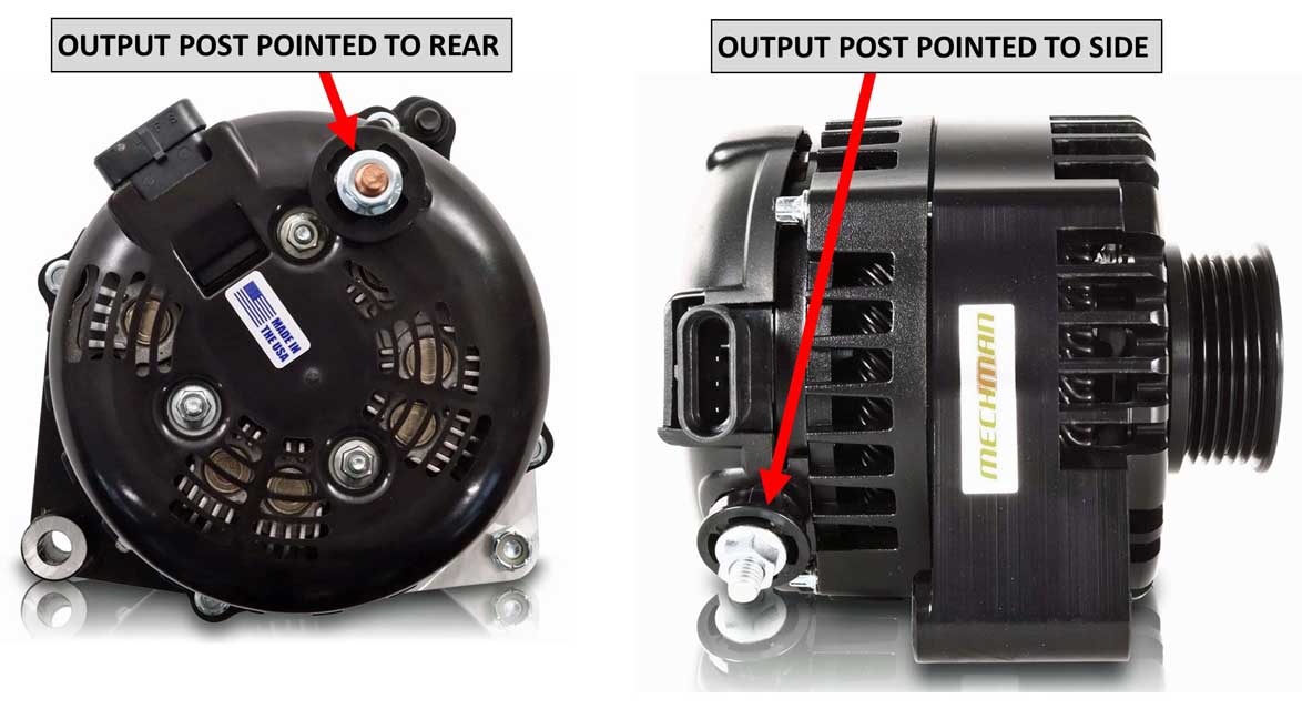 Note about the alternator POWER OUTPUT lug: In this photo above you can see the B+ output lug may be pointed to the rear or to the side. I'm using one that's pointed to the rear. If requested, Mechman offers the option of either configuration. |
||
 Mechman Elite and S Series alternators employ cutting edge alternator technology not found in other aftermarket alternators. 6 phase hairpin stators make Mechman Elite and S Series alternators fundamentally more efficient than other aftermarket alternators. This new technology and increased efficiency equates to incredible output at extremely low engine RPM, less energy wasted in the form of heat, and more horsepower to the wheels. Also because less heat is being generated, the internal components of Mechman Elite and S Series alternators last longer. This is especially beneficial on turbocharged and/or endurance racing vehicles with high engine compartment temperatures. All Mechman Elite and S Series alternators feature soldered stator and rectifier connections, with epoxy re-enforced stator connections, reducing the chance of vibration failures. High Pole Count 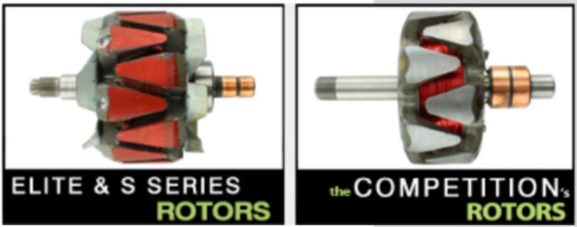 Mechman Elite and S Series units are built exclusively with precision balanced low-mass rotors that allow them to operate safely at shaft speeds of 20,000+ rpm. This high RPM capability, combined with excellent output at idle, gives the user a much broader operating RPM range, and more flexibility in the size of the crankshaft pulley used. A properly selected Mechman Elite and S Series alternator can even fix low voltage problems caused by using small diameter, or "underdriven" pulley ratios. The higher pole count in the rotor also results in less electromagnetic interference to cause problems with radios and other electronics. Twin Rectifiers  As a final precaution, Mechman Elite and S Series alternators are constructed with twin high efficiency cooling fans, and twin internal rectifier plates. While other high performance alternators have only one rectifier with 6 diodes. Mechman Elite and S Series units boast 12 press fit diodes with 300% more surface area to dissipate heat. These considerations to cooling airflow and heat dissipation make Mechman Elite and S Series high performance alternators the most durable aftermarket alternators you can buy. If you are experiencing pre-mature alternator failure, intermittent electrical accessory problems, or low voltage at any engine RPM, a Mechman Elite or S Series alternator is the answer! |
||
|
||
|
||
Here are the dyno specs for this 6 phase alternator,
Mechman PN B8206170M. As you can see it puts out 145 amps at idle and 185 amps while cruising.
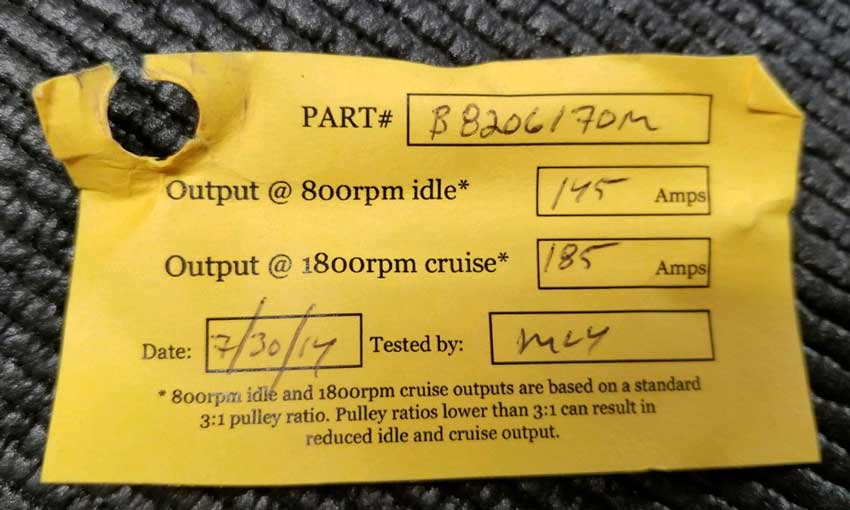
That sounds impressive but what does that mean in real life?
Impossible you say? I would have doubts too if I didn't see it for myself. So yes, if you can afford it, buy a 6 phase hairpin stator alternator. |
||
|
|
||
|
| ||
|
And this video shows the fully HOT alternator voltage when getting a full load. https://www.youtube.com/watch?v=T5c_6JGEplo |
||
|
|
||
While the above reading may seem deceiving, the actual voltage drop measured at the BATTERY is shown below.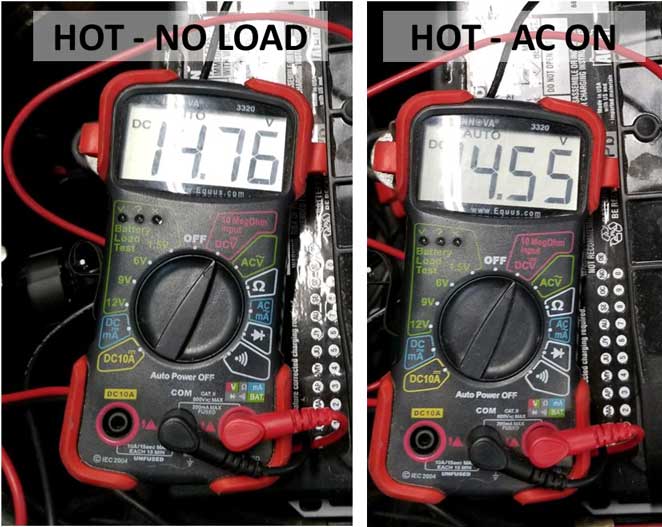 |
||
|
|
||
| IDLE SPEED I've mentioned in a couple places in this page that sometimes I have increased my idle speed to improve charging. This was an absolute must when I was using a Volvo BOSCH alternator and back then I had to keep idle at 1000 RPM or voltage would drop too low. With a Mechman this can be a subject to pay attention to also, but for me it was not nearly as important because the Mechman charged better at low RPMs. Every car is not the same. My 1984 240 Turbo factory idle speed is 900 RPM. I typically run my car at about 950. Most non-turbos recommend 750 ±50 RPM. I know some MECHMAN users are running their idle below 700-800 RPM, but I think 700 RPM might be pretty much as low as I would go with a Volvo 4 cylinder and with an alternator like this. You'll probably find there's a certain RPM threshold where charging begins to drops off if you dip too low, so adjust accordingly. |
||
|
|
||
|
||
|
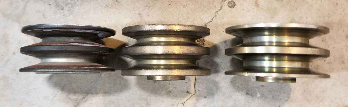
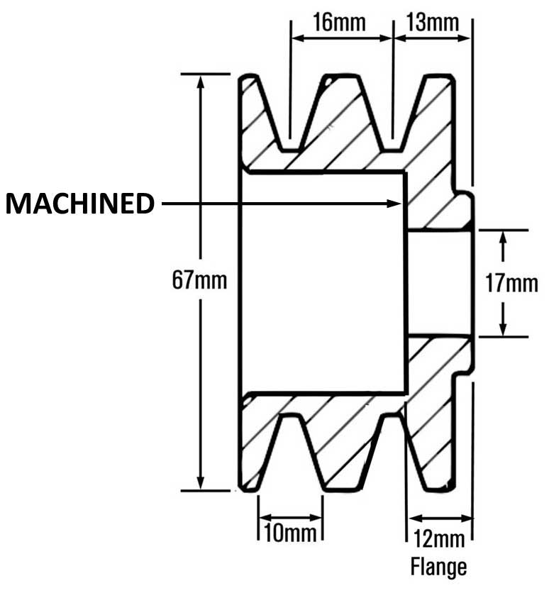
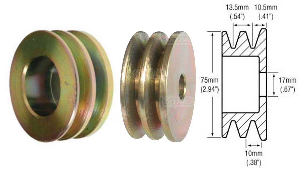
| FITTING A
UNIVERSAL HIGH-PERFORMANCE ALTERNATOR TO A 240 |
Here's a good selection of 2-groove pulleys, all machined from cold-rolled steel . alternatorparts.com/2-groove |
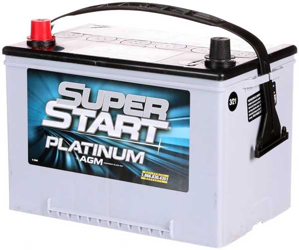
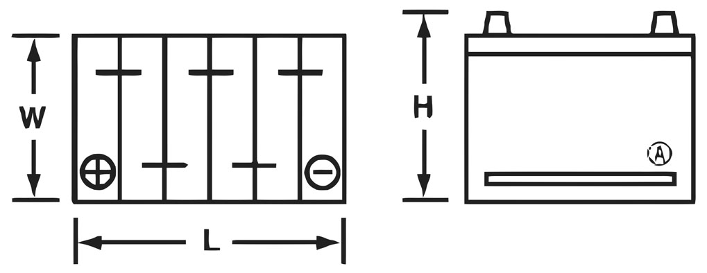
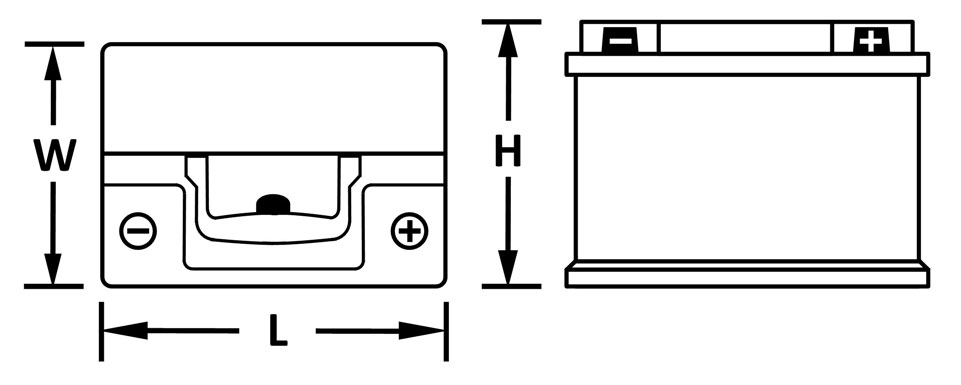
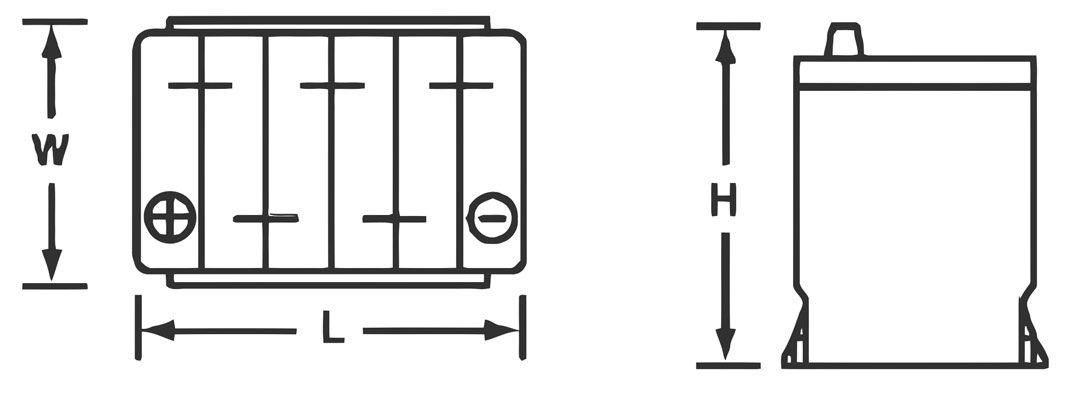
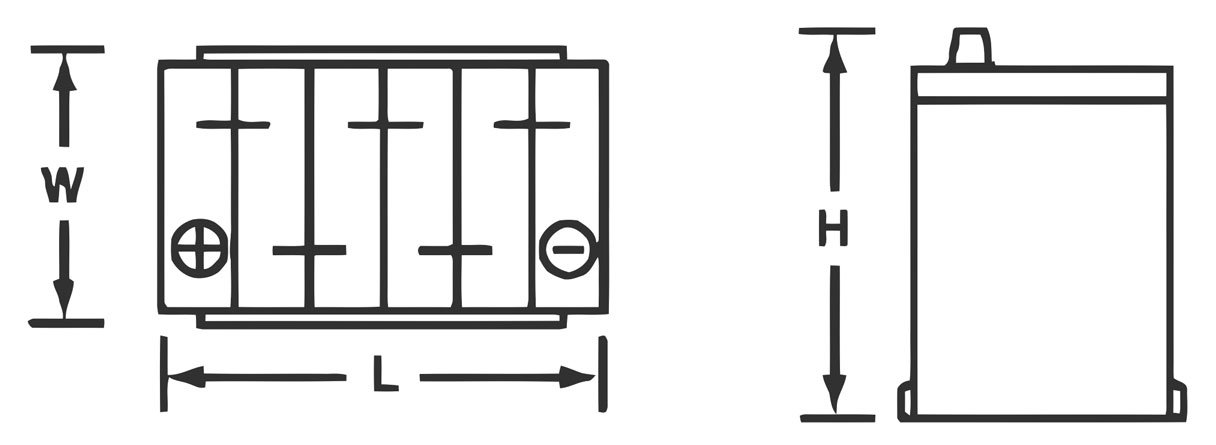
 An AGM battery means it's constructed using Absorbed Glass Mat, which is superior in design to an old school flooded lead acid battery. I picked this battery brand because it's made by East Penn Manufacturing, who has been known for making the revered Deka battery line. I've been very happy with this type of AGM in my car for many years. BCI Battery Group Sizes BCI Group Sizes are standardized sizes. A PDF document of all sizes can be found at: https://batterycouncil.org/wp-content/uploads/2023/10/BCI-Group-Sizes.pdf Commonly used sizes for Volvo 240.
ALTERNATOR CHARGING VOLTAGE The Mechman alternator I use typically keeps alternator output between 14.6 and 14.7 volts when things are good and hot and stable. This seems to be OK for this AGM Battery and I think it's not excessive. Most high performance AGM battery manufacturers warn against overcharging when using a battery charger (sometimes warning to not charge above 14v). Charging with a battery charger is not the same as an ALTERNATOR maintaining a charged battery. Most published recommendations for alternator charging are between 13.8 and 14.8 volts, while some I've seen recommend up to about 14.6 volts. I've seen recommendations from Interstate Batteries for not over 15 volts for an AGM. Keep in mind any of these recommendations always comes with temperature variables, so try not to take them as absolute. For example, you can see how recommended charging voltages will change dramatically depending on ambient temperature in XS Power Battery guidelines. This PDF below used to be in their pages, but no longer, but I saved it: https://www.davebarton.com/pdf/BATTERIES_XS_Power_PSseries_Instructions.pdf Most guidelines will agree that ALTERNATOR charging below 14 volts is getting very close to insufficient for an AGM battery. Here's a very detailed PDF document from East Penn Manufacturing on GEL versus AGM. They offer both, but a GEL battery is not the same as AGM. The recommendations between them are quite different for charging voltage too. https://www.davebarton.com/pdf/Batteries_East_Penn_Gel_or_AGM.pdf This image below is from page 11. 
|
|||||||||||||||
|
|
||||
| davebarton.com |
prancingmoose.com |
240turbo.com |
Special Emblems |
|
| Prancing
Moose Stickers |
Volvo
Stickers |
Body/Chassis/Engine
Labels |
240 MODS and FIXES Page | |
| Other Car Brand
Stickers |
Steering
Wheel Labels |
Center Cap Labels/Overlays |
Cool Volvo
Products |
|
| Grill Labels/Overlays |
Volvo Wire
Harnesses |
Conversion Harnesses |
Harness
Parts/Connectors |
|
| Volvo Relays |
Coil Repair
Harnesses |
240 Window
Scrapers |
740/940
Window Scrapers |
|
| Adjustable Voltage
Regulators |
Horn Buttons |
240 Odometer
Repair |
740 Odometer
Repair |
|
| Volvo Gauge
Faces |
740
Turbo/Boost Faces |
240 Black Door Vinyl |
850 Odometer
Repair |
|
| ALTERNATOR Page |
240 Power Mirrors - Switches |
240 Oil Cooler Page |
240 Fuse Panel Page |
|
| Group A
Racing 242 Turbo Page |
240 Hydraulic Clutch | Fuel Pump RELAY Page |
240 Headlight RELAY Page |
|
| Used Parts & Extra Stuff for sale |
CRIMPING Page |
240 Ignition Page |
240 Headlight Page |
|
| 240 Gauge Electrical Diagrams | 240 REAR END Page | Yoshifab Catch Can Install | 240 TAILLIGHT Page | |
| Side Marker
Lights Page |
Gentex Mirror Upgrade | Yoshifab Drain Tube Install | Modified 240 Favorites | |
| SoCal Salvage Yards | Unleaded Racing Fuel | B26FT Stroker | Dave's 245 Spec Page | |
| 240 SUSPENSION Page | 240 Lowering Page |
240 Windshield Page |
240 WIPER Page | |
| 240 BRAKES Page |
240 Dash Top Gauge Pod | Cadillac 4-Note Horn Install | 240 DYNAMAT Installation | |
| 4 Speed Fan
Controller |
Electric Cooling Fan
Page |
BRUSHLESS Cooling Fan Page |
Tropical Fan
Clutches |
|
| 240 AC Page | "KOMFORT BLINKER" Upgrade | T5 Trans Conversion Page | 240 Engine Mount Page | |
| 240 VIN Page | Stepper Idle Valve Page |
Vacuum Diagrams | 240 HOOD Page | |
| 240 Exhaust Page | 242 Power Vent Window Project |
EFI Volvo Pin Function Diagrams |
Favorite Links | |
| R-Sport
Apparel |
Prancing
Moose Apparel |
Volvo Meet Photo Albums | Texas Volvo Meets and Events | |
| Ordering Instructions | Policies | PAYMENTS Page |
Mojave Road Trail Map Page |
|
| Returns | Shipping | Shopping Cart Troubleshooting | Contact Us |
|


 alternators are known for poor voltage.")


