|
2 4 0 T U R B O . C O
M D A V E ' S V O L V O P A G E
|
||||||||||||||||||||||||||||||||||||||||||||||||||


 alternators are known for poor voltage.")


| So I thought I would put together
a page to keep track of the hydraulic clutch parts I have put in my
240 or researched and all the other things I've learned about this stuff over the years. Nothing here is for sale (at least from me). |
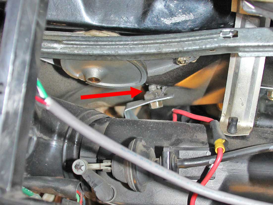
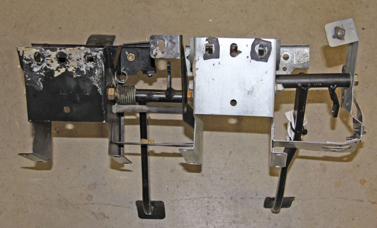
 Here's a lengthy TB discussion on this if you want more info. I don't have any of THIS info in my page here. turbobricks.com/tilton-hydraulic-release-bearing.357178/ So why haven't I tried this? Reason #1: This release bearing was a pretty unknown subject back when I first did this conversion. Reason #2: I didn't want to be the guy who posted this: "I had a lot of issues using these Tilton throwout bearings on Randy's flyin' moose car using M90 trans. We went back to the oem style and have never looked back." SOURCE: turbobricks.com/tilton-hydraulic-release-bearing.357178/page-3#post-6373384 Nowadays there might be more experience behind users of this bearing. So one of these may be something to reconsider. Here's a video showing how a Hydraulic Release Bearing is generally fitted. https://www.youtube.com/watch?v=QlItEBpbqSs CABLE vs HYDRAULIC PEDALS First here are some basic CABLE CLUTCH diagrams from the 1981 New Car Features book. 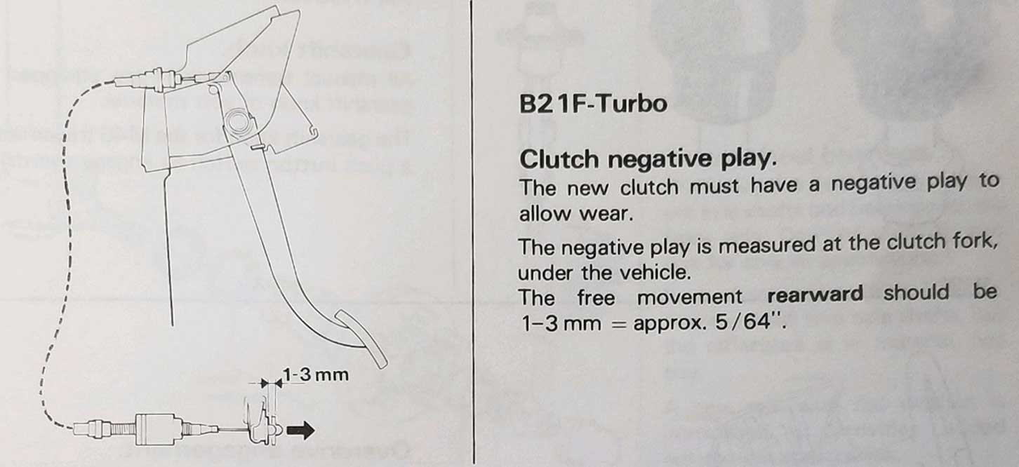 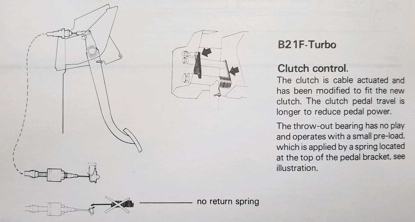 If we assume this CABLE pedal has 170 mm travel as shown (with a pedal fulcrum ratio of 5.18 to 1), the cable at the firewall will travel about 32.8 mm. (Pedal dimensions here) 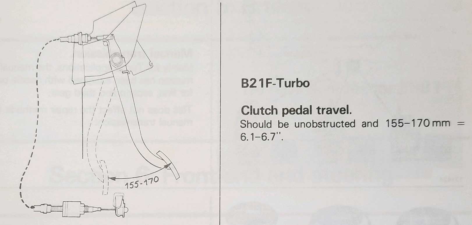 This cable fork PN 1212189 has a fulcrum ratio of 320/115mm: 2.78 to 1. This ratio means that the cable travel of 32 mm at the fork end will push about 11.5 mm at the clutch release bearing. 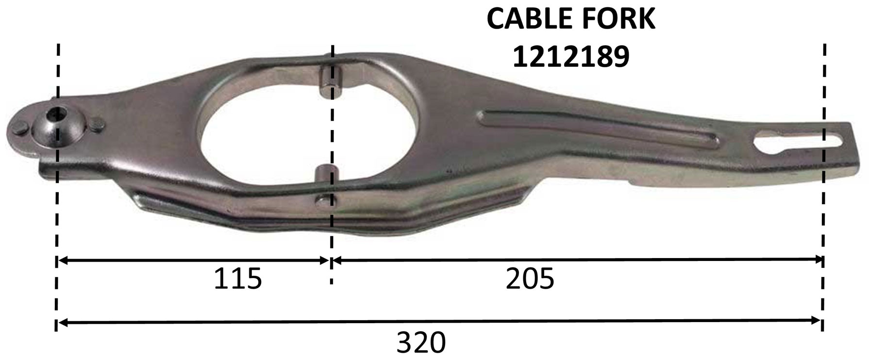 And here is a diagram for the 240/260 HYDRAULIC CLUTCH. 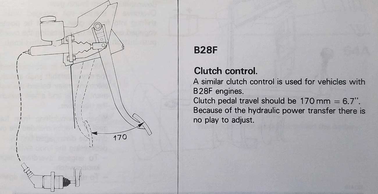 If we assume this HYDRAULIC pedal has 170 mm travel as shown, with a pedal fulcrum ratio of 6.7 to 1 (assuming the pedal dimensions are accurate), the master cylinder pushrod at the firewall will travel about 25 mm. (Pedal dimension diagrams here) Note this image above states there is "no play to adjust." This is true with regard to the pedal, but there is some adjustment available at the fork by spacing the clutch pivot ball closer to or further from the bell housing. The clutch pivot ball can be seen below CLICK HERE. Regarding 25 mm of Push Rod Movement at the MC If there is 25 mm of push rod movement at the master cylinder, we can use that to determine how much or how far a hydraulic system can push the clutch. This requires an understanding of the fluid volume being pushed in the master cylinder versus the fluid volume in the slave cylinder. If we start with the factory piston bore of the 240/260 FAG master cylinder: 19 mm (0.75 inch), and the factory 740 slave cylinder, which has a bore of 22.2 mm (7/8 inch), this means the 25 mm of initial movement in the master cylinder will become just over 21 mm of movement at the slave cylinder and clutch fork end. And since the hydraulic clutch fork has a fulcrum ratio of 1/2 (70/140 mm), then the movement of the release bearing against the clutch fingers would be about 10.5 mm. Is that enough? Good question. It's hard to know for certain, since I haven't found any standard info for this which says what factory specs were supposed to be (Hydraulic Fork dimension diagrams here). 240 FIREWALL INFO Some 240 driver side firewalls have holes already present for clutch components. Some do not. This is the driver side firewall plate from a LHD 240. The large lower hole near the bottom is where the steering column goes through. Most early 240s I've seen will look like this. The diamond shaped metal cover is covering the position for a hydraulic clutch master cylinder. So converting an auto car to manual or installing a hydraulic clutch master cylinder may not require altering the firewall if you have this firewall plate. Some 240s, however, have a firewall plate WITHOUT the clutch holes.  Here's a driver side firewall plate from a LHD 240 BELOW which came WITHOUT any holes for clutch controls. I have no idea why Volvo thought it was a good idea to eliminate the holes. If you have a 240 like this, you can try finding a different firewall plate, however swapping this plate can be difficult, since it requires removing the steering column. The other option is to drill a few holes. If you have a brake pedal box assembly for a manual transmission 240 you can use the holes on that box to guide you.  For some perspective, here's what the CABLE TYPE CLUTCH PEDAL looks like. For a hydraulic clutch conversion, the clutch pedal must be changed to a hydraulic type pedal.   Here's a hydraulic pedal in place. And using the pedal bracket for reference, we can see where the holes need to be for the hydraulic clutch master cylinder. You can use the pedal bracket as a template to locate the holes and figure out precisely where to drill.   Learning some Hydraulic Clutch Basics If you're a beginner at this subject or if you want to learn more of the basics, I think you would benefit from watching the below 6-part series on Hydraulic Clutches 101. youtube.com/watch?v=m0bMac1 | |
|
Lets look at the basic differences between a cable clutch and a hydraulic clutch.
The below article was first published in the Skandix web page: skandix.de/clutch-actuation Clutch actuation - The Differences Some Volvo models were produced with both hydraulic and cable-operated clutches, and the M46 and M47 transmissions were also installed in several model series.
This makes it possible for different types of actuation to be found in
the same clutch bell housing. For example, an early Volvo 740 can
usually be converted to a hydraulic clutch without any problems. With hydraulic clutch
actuation, the slave cylinder presses on the release lever. To ensure
that the release bearing is pressed forwards, the release lever is
mounted on the pivot pin to the left of the release bearing. The pivot
pin is screwed onto a stud bolt, which is screwed into a nut inserted
between the bell housing and the gearbox housing. The height of the
pivot pin can be varied using two different lengths and washers. On the
pivot pin there is either a plastic ball socket to reduce friction or a
locking spring engaged in the release lever. With cable clutch
actuation, the clutch cable pulls on the release lever. To push the
release bearing forwards, the release lever is mounted on the pivot pin
to the right of the release bearing. The pivot pin is firmly riveted to
the release lever. It is held by a screw on the right-hand side of the
clutch bell housing. 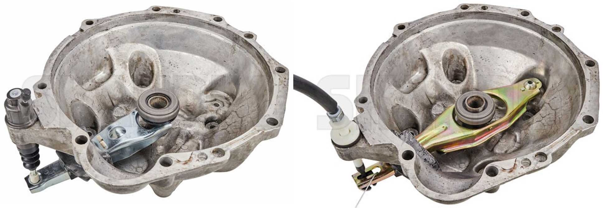 You'll see the below left photo again later, but I wanted to show how the Volvo bell housing will accommodate a pivot ball for EITHER a cable clutch or a hydraulic clutch. This allows for the cable to PULL a CABLE clutch fork when the pivot ball is in the cable clutch location. More detailed bell housing and pivot ball info can be found here.  And if the pivot ball is in the hydraulic clutch location, it allows the hydraulic slave cylinder to PUSH the HYDRAULIC clutch fork. This slave cylinder is from a 740 or 940.  |
|
My 240 conversion from Cable to Hydraulic was completed in 2011.
INTRODUCTION OF THE VOLVO FAG 260 HYDRAULIC MASTER CYLINDER
This is the Volvo 260 clutch master cylinder I used, Volvo PN 1205729, manufactured by Fag. An aftermarket MC was available as Centric PN 136.39000, but probably no longer. This FAG master cylinder was used in the manual trans 264 in North America and in all manual trans 240 models in the UK and Australia because those were right hand drive. It was still available new when I started my conversion in 2011. If not, then you can pursue an aftermarket MC, such as Tilton or Wilwood. The inner piston bore diameter is for this FAG master cylinder is 19 mm (0.75 inch). The hose port is 12 x 1.0 mm Inverted Flare (AKA: Double Flare). This is quite different from the 10 mm Bubble Flare that Volvo used in brake systems. It used a metal pipe like this photo below. 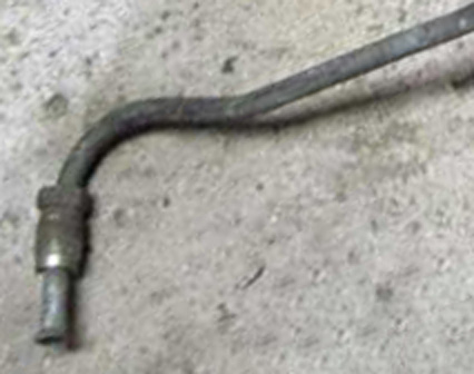
|
|
|
|
|
|
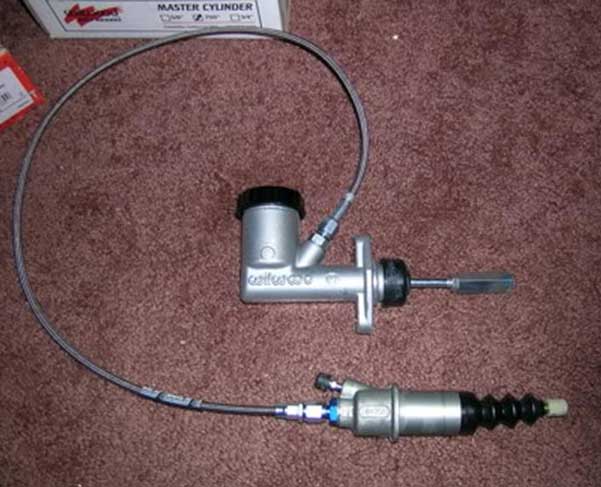
So then I
needed a clutch hose to mate the FAG MC to a Slave Cylinder.
Back in 2011 I was able to locate a USED original 740 hose (like this one shown below). It had a hard line beginning at the master cylinder and it then transitioned to a flexible hose further down. I also chose the same 740 slave cylinder seen in this photo below. It was originally made for a 740, but it fits perfectly in the 240 bell housing since the bell housing is the same. 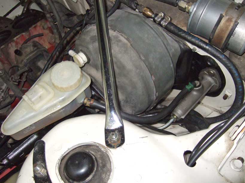 Note the different looking clutch master cylinder in the photo below. That's a 740 MC for a manual trans 740. The 740 did not use a fluid reservoir for the clutch MC. Instead this MC received fluid from the brake MC reservoir through a hose, as you can see below. The length of this 740 clutch master cylinder is longer than the Fag MC. This 740 Clutch master cylinder is known as Volvo PN 8601785 (also 1273680, 1330248, 1330249). The inner piston/bore is 19 mm (0.75 inch). Same bore size as the 240 Fag master cylinder. The outlet port is same as the 260 FAG MC, 12 x 1.0 mm Inverted Flare (double flare). 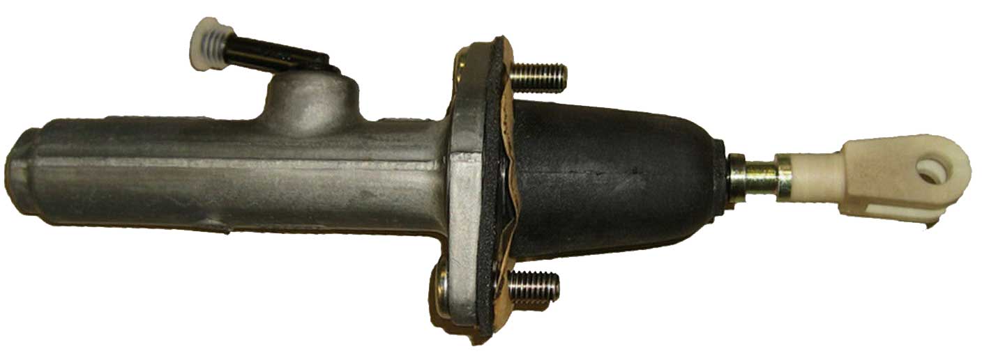 The STROKE or length of travel of this master cylinder is 25 mm (1 inch). This is shorter than the Volvo 260 FAG, which is 33 mm (1.3 inches). The shorter stroke could limit the clutch travel. turbobricks.com/clutch-master-slave-cylinder-riddle.370314/ |
|
|
|
|
| Building your own clutch hose or having one built. An original Volvo 264 hydraulic clutch hose will not be easy to find. ONE OPTION: This image below is a banjo adapter fitting which can be found online. The thread size is 12 x 1.0 mm and it will fit the FAG clutch master cylinder outlet. It then uses the AN -3 end for the hose fitting. Search for "Steel M12x1.0 to 3AN banjo fitting". 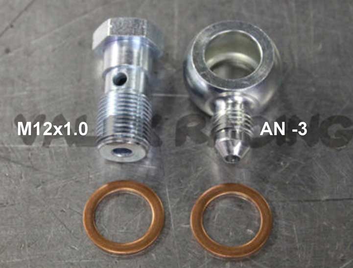 Optionally you can choose -4 AN hose, but for this info I will show info for -3 AN hose. Using a banjo fitting on the MC can help with a tight fitting master cylinder that has very limited room for the hose to turn before hitting the fender. Using adapters shown here is possible or you can seek out a pre-made hose or build one yourself. A proper length can be about 30 inches. If you buy the parts to build one yourself, choose a hose type that is rated for high pressure, such as this: pegasusautoracing.com/Product=3260 or https://www.summitracing.com/aer-fcc0303 These Stainless Steel Braided PTFE Brake & Clutch Hoses can handle 3000 psi. Here are some hose ends in -3 AN size: pegasusautoracing.com/productdetails=4154. Pegasus PN 3261-3-00 straight 3AN hose end. |
|
| This info will help if you want to build a hose with a FLARED HARD LINE at the Master Cylinder. If you prefer a hard line like this below, you'll need to flare the pipe. So you'll need a flaring tool or someone who can flare this line. This hard pipe is very similar to brake line, but normally this clutch line is larger than a typical 3/16 inch (4.75 mm) brake line you have on your 240 brakes. The photo below compares the clutch hose to a 240 brake line. The larger size pipe (shown below on the MC) is 6 mm hydraulic pipe. The flare type at the MC needs to be Inverted Flare (AKA: Double Flare).  It would be possible to use small 3/16 inch brake line. If you do, you can use this flare fitting fitting below at the master cylinder. Select DOUBLE/INVERTED and 4.75MM (1 needed). Or if using the larger 6 mm brake line (as in the photo), you can select DOUBLE/INVERTED and 6.0MM (1 needed). https://belmetric.com/m12x1-0-brake-end-double-bubble-flare-4-75mm-6-0mm-line/ Then on the other end of the hard line, it should transition to a flexible line. You can use a similar fitting, except in my opinion this end should be flared as a bubble flare (which is normally used in Volvo brake lines). For 3/16 inch line, that would mean your would select BUBBLE and 4.75MM (1 needed). Or if your going with 6 mm line, select BUBBLE and 6.0MM (1 needed): https://belmetric.com/m12x1-0-brake-end-double-bubble-flare-4-75mm-6-0mm-line/ This fitting above can then be mated to an adapter, which will adapt the 12 x 1.0 mm flare fitting to an AN -3 hose end fitting. This one will do it (1 needed): https://www.summitracing.com/parts/cst-sbh8069. HOSE: So then the high pressure flexible hose in size AN -3 can be like this: https://www.summitracing.com/parts/aer-fcc0303 with a hose end like this on each end (2 needed): https://www.summitracing.com/parts/aer-fbm1100. |
|
| Here's a useful video showing how to assemble a hose like this. https://www.youtube.com/watch?v=5tdsgZ-KfWI |
|
|
|
|
|
Here are some
adapters that will fit the 740 slave cylinder, which has M12x1.0 threads.
The hose side will use either AN -3 or AN -4
thread. You can search for "Steel M12x1.0 to 3AN adapter" or "Steel M12x1.0 to 4AN adapter".
Or something like this: https://www.summitracing.com/parts/ear-592053erl You should use a brass sealing washer on the M12 side (the side going to the slave cylinder). Or as a better option that I used, I suggest a metal-bonded sealing washer shown below.  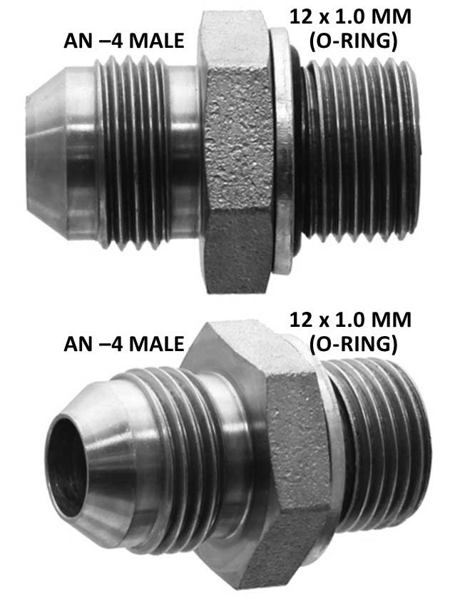 METAL BONDED SEALING WASHERS 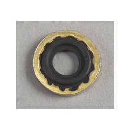 This is a metal-bonded sealing washer above. It has a rubber o-ring embedded in it. A sealing washer is generally used when a flare fitting is not used, such as on the M12 end of this adapter above. McMaster Carr has these washers: mcmaster.com/#standard-washers/, click "Sealing Washers," then "Metric High-Pressure Metal-Bonded Sealing Washers." Your local hydraulic hose shop may have them too. They can also be found at Pegasus Racing, called Stat-O-Seal Sealing Washers: pegasusautoracing.com/Product=3245 You might be thinking this hybrid washer above is inferior to an all-brass washer. You would be wrong. It can handle thousands of PSI and will easily out-perform the sealing capability of an all-brass washer. The custom clutch hose I had assembled in 2017 by a hydraulic shop can be seen a bit further below or CLICK HERE. |
|
|
|
|
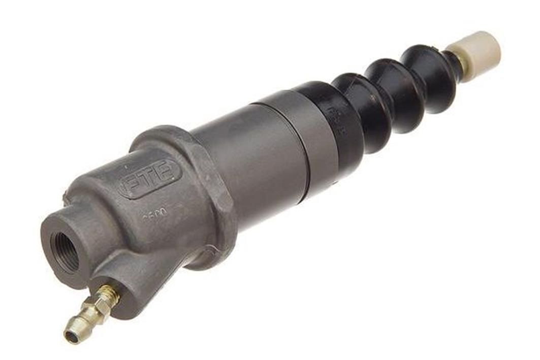
| The 740 slave cylinder is made to be a perfect
fit on a typical M46/M47 bell housing. Volvo PN 8601783 (older PNs 1205733, 1273681, 6843913). The circular mount on an M46 or M47 bell housing is designed to hold either the cable end for a cable actuated clutch or it will hold this slave cylinder. This slave cylinder came standard on a 740 or 940 with a manual transmission. This part (and a number of aftermarket versions) is still available from a number of sources. The machined barrel that slides into the mount had an outer diameter of 32 mm or about 1.26 inch. This slave cylinder is retained in the bell housing mount with an external snap ring (shown in detail further below). 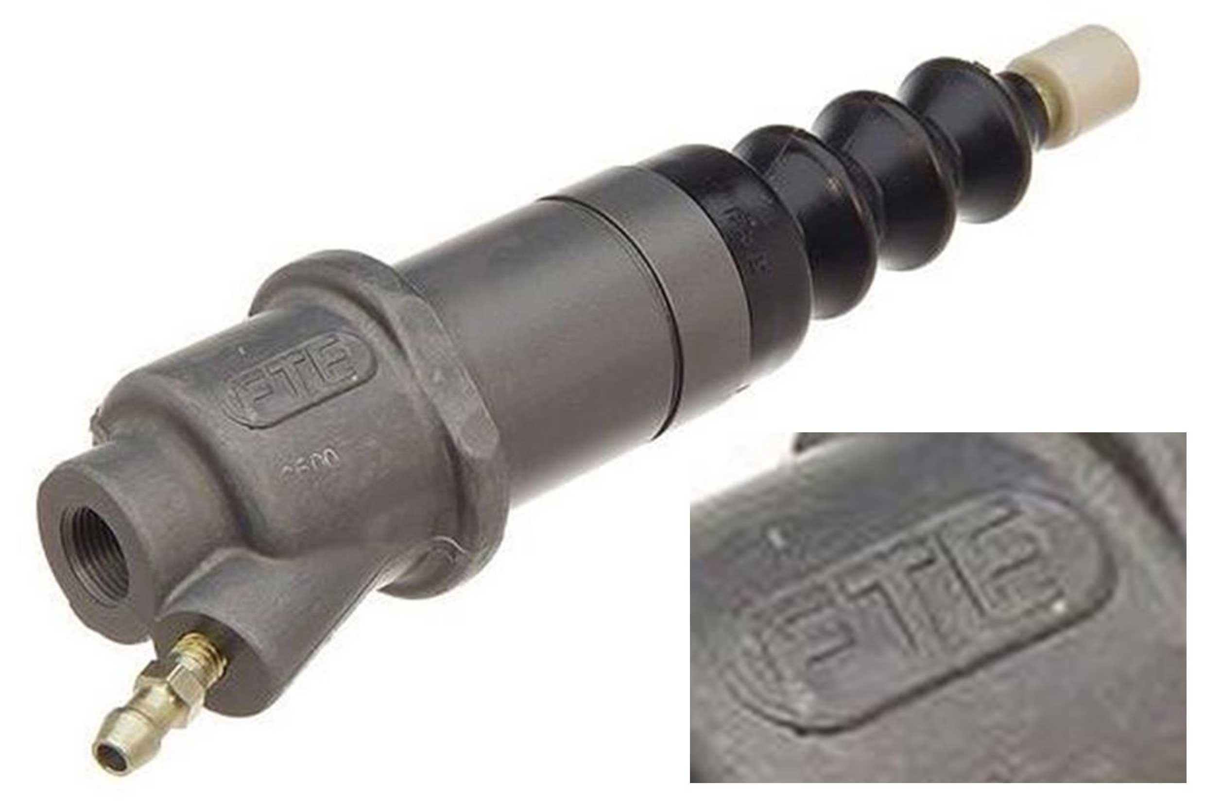
This slave cylinder pictured above is marked FTE. This brand is made in Germany and appears to be a good version. I had an opportunity to disassemble an FTE slave and I found the rubber piston seal inside was marked FAG. The inner piston bore for this slave cylinder is 7/8 inch (22.2 mm) The piston stroke is up to 1.75 in (44 mm), however only a portion of that is needed. 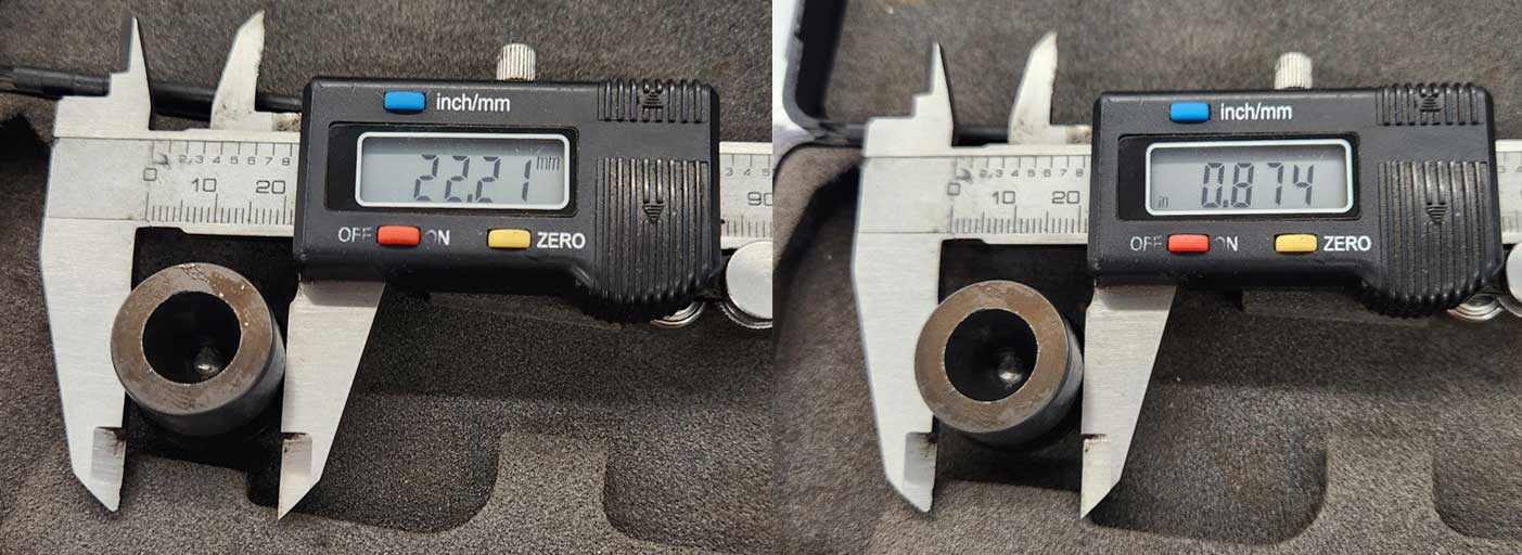 Be aware there are some very early Volvo bell housings (pre-B21F) possibly for P1800s, 122s or 140s. Those have a different configuration and use a different type of slave cylinder. You're on your own with that type, since I have no useful info on that one. 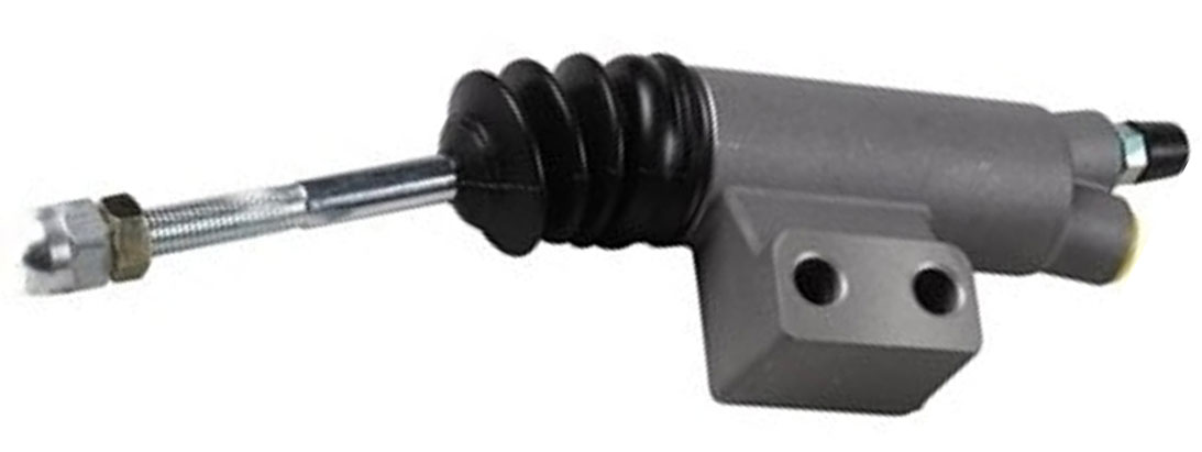 |
|
|
|
|
This 740 slave cylinder has an inlet port threaded 12 x 1.0 mm. It's machined at the bottom for a bubble flare (this different from the 240 FAG MC), so if you prefer, you can use a 12 x 1.0 mm Bubble hose end or adapter fitting. The face of the port is also machined flat, so you can optionally use a 12 x 1.0 mm fitting (or banjo) which accepts a sealing washer. This may be a brass, aluminum or metal-bonded sealing washer. The second photo below shows what the original hose end looks like for the 740 slave cylinder. The thread is 12 x 1.0 mm Bubble Flare. It's pictured below next to a 240 brake line for comparison.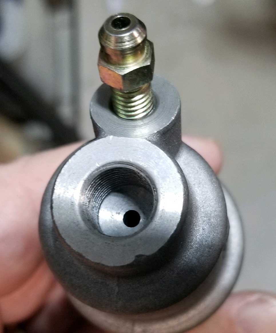 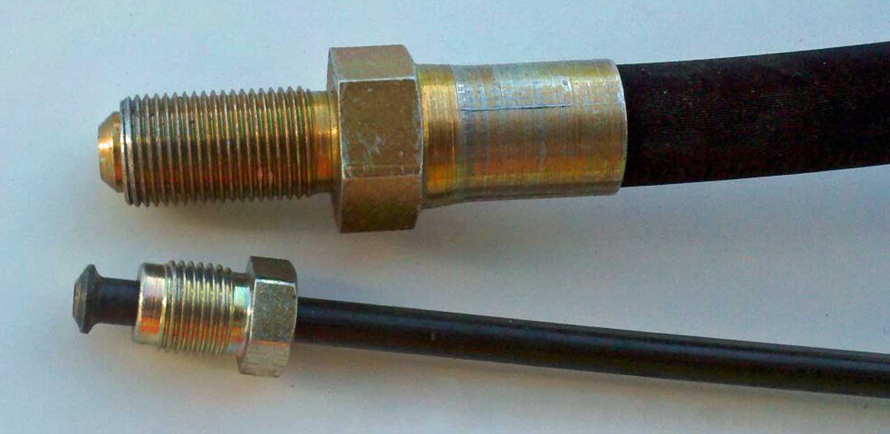 |
|
|
| |
|
And you'll need this EXTERNAL SNAP RING (AKA: external circlip or retaining
ring) to keep the slave cylinder locked in the
mount on the bell housing.
It's Volvo PN 914463 (part number for 740 part). Inside diameter is 30 mm (same as 1 3/16 inch or 1.187 inch). 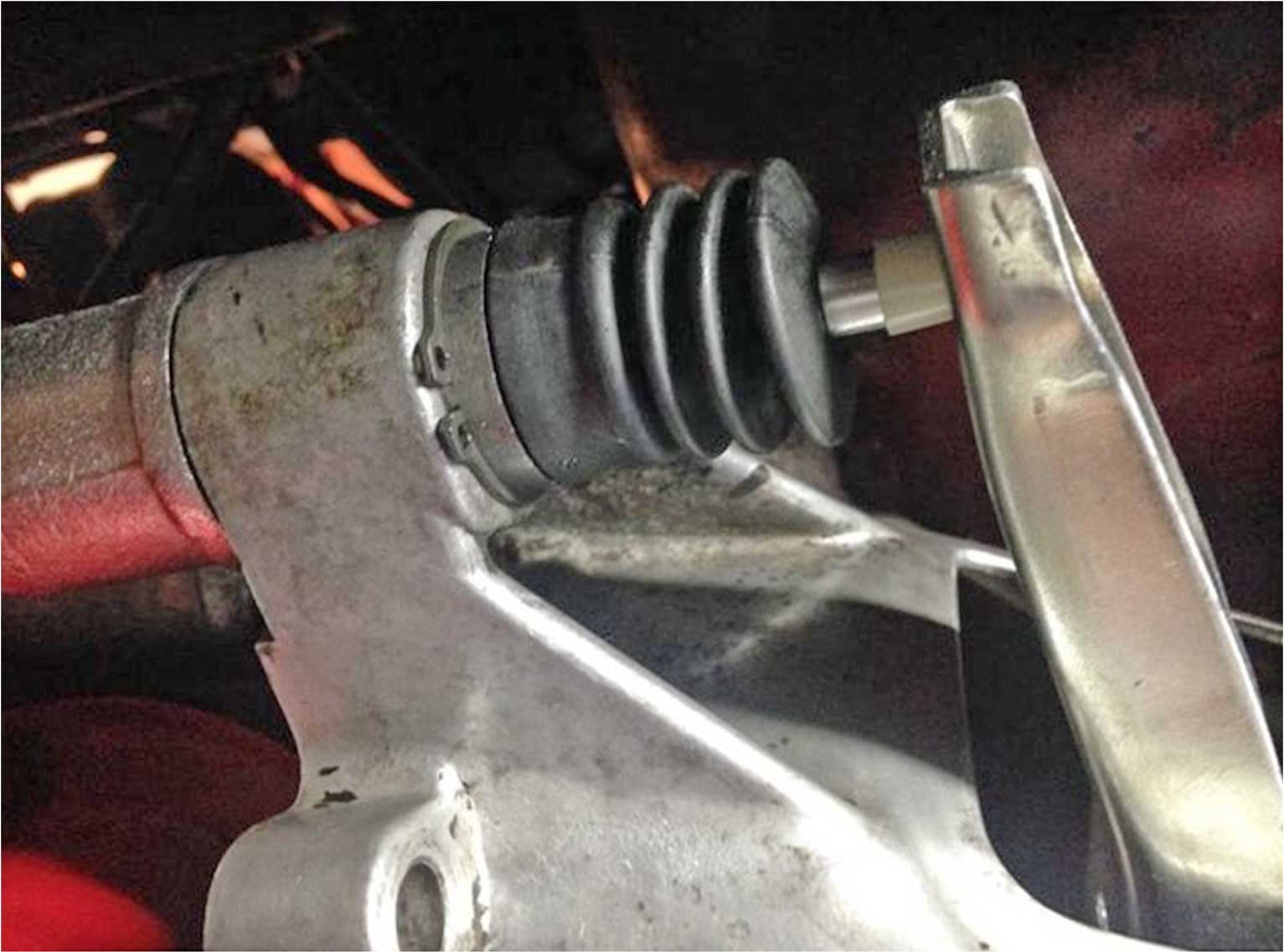 Here's the snap ring in place. |
|
|
|
|
|
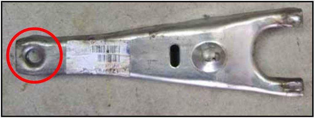
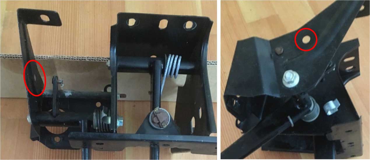
CAUTION: If you have clutch fork PN 1220763 with the hole at the end, be careful of
this little PLASTIC END CAP found on the push rod on the Volvo 740 slave
cylinder.
If your clutch fork has this hole where the plastic end on the push-rod pushes, you could experience a failure like I did below. 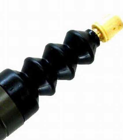
 |
|
|
One
minute you have a nice working clutch. The next
minute your pedal goes to the floor!
Because of THIS. The white plastic end cap sheered and the push-rod went right through that hole in the fork.  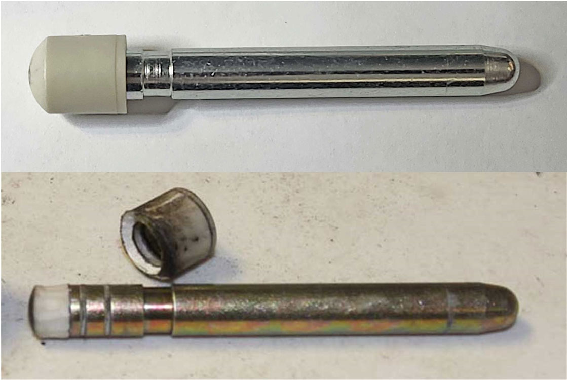 |
|
So I then drilled that hole out in the hole in the fork slightly and installed
a large socket head bolt in there so the end of that rod rests in the center of
that socket head. 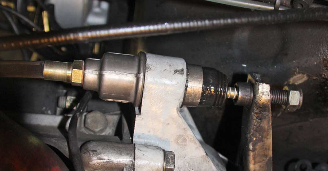  |
|
|
|
|
|
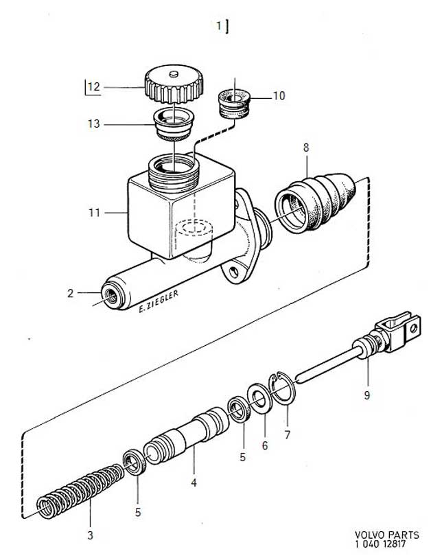
Here's a useful
diagram showing 240/260 hydraulic clutch components.
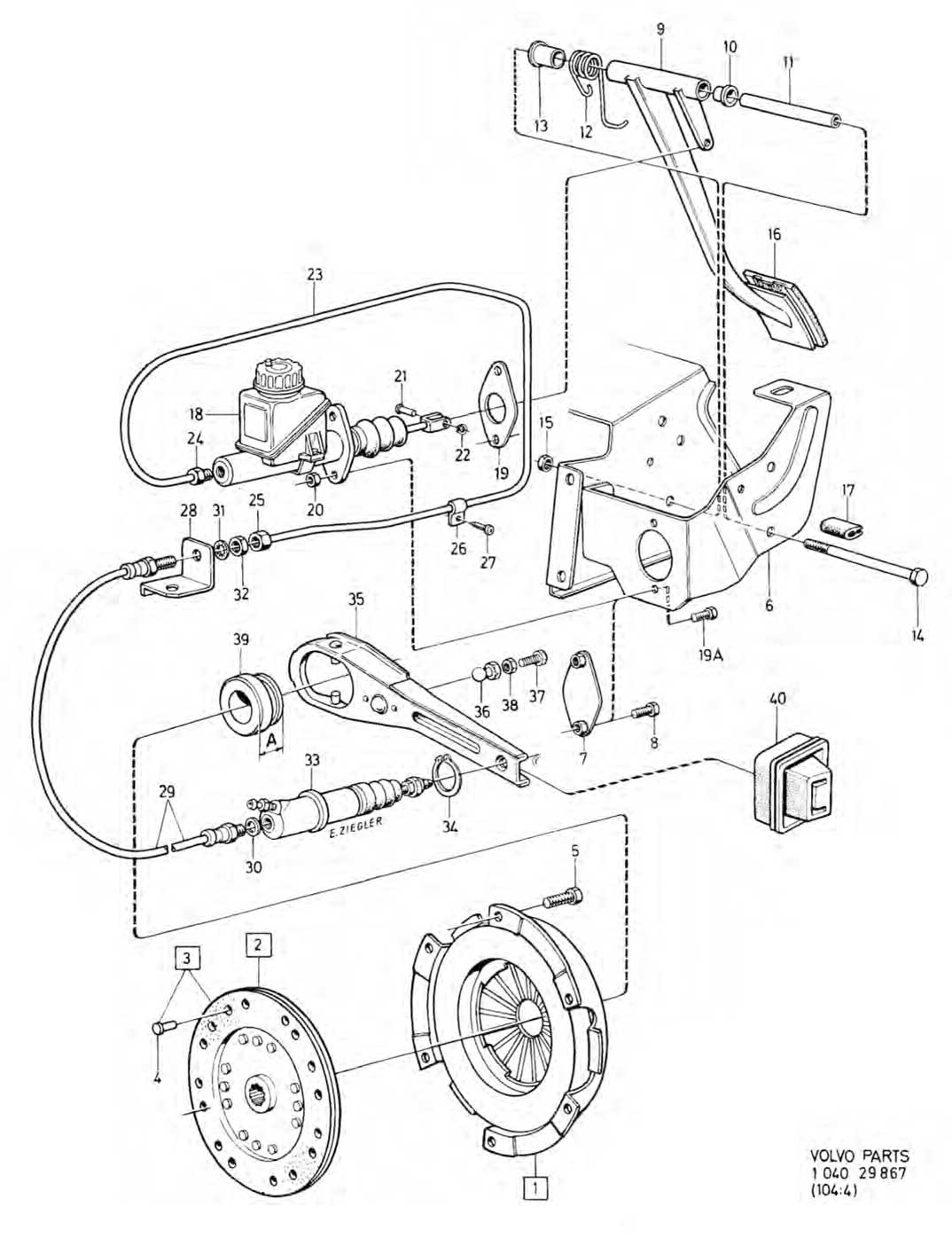 Not all part numbers listed here will be found to be a current or latest part number catalog. If you find information that you can help to improve in this page, please let me know. 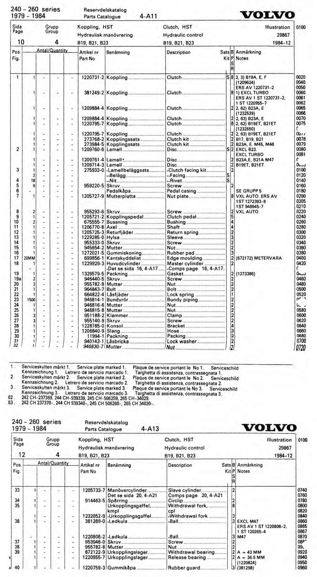 |
|
|
|
|
|
Converting
from a cable to hydraulic clutch requires that you
have a compatible bell housing.
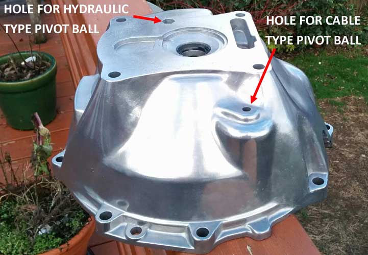
These TWO photos below show a LATER TYPE M46 or M47 bell housing. One part that gives it away as a later type is the opening at the top of the bell housing (top-left in this first pic below) for a crank position sensor, which came on 1989 and later cars. That's not really important for this discussion. Just a bit of trivia in case you need that port for a crank position sensor. 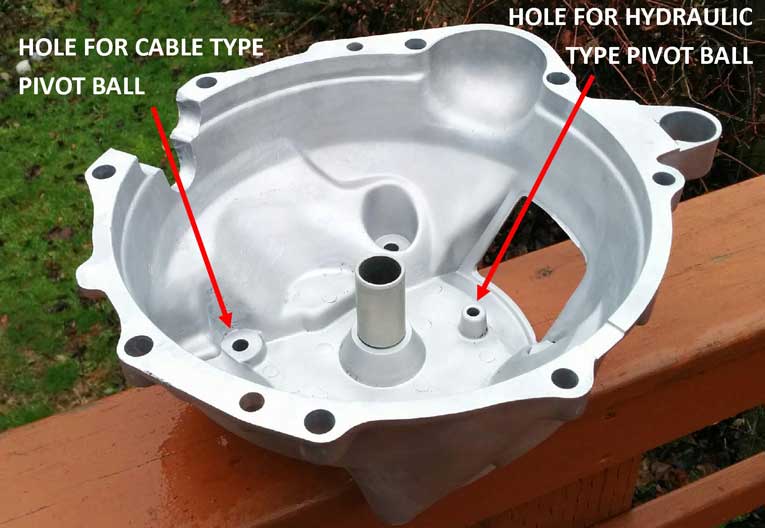 You won't necessarily need a bell housing that has an opening for a crank position sensor unless you're using an engine management system that requires it, such as LH 2.4. The important thing is that the bell housing should have the second pivot ball mounting hole for a HYDRAULIC CLUTCH FORK. There are some early (pre-240) M46 bell housings that do not have this second hydraulic mounting hole. |
|
|
|
|
 Here are some close-up images of the back side of the hole for the hydraulic pivot ball. The 13 mm head of an M8 bolt will fit in there. 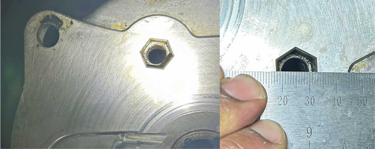 There is more than one style of pivot ball. Some are short and some are tall. 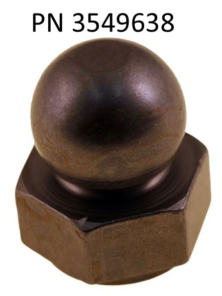 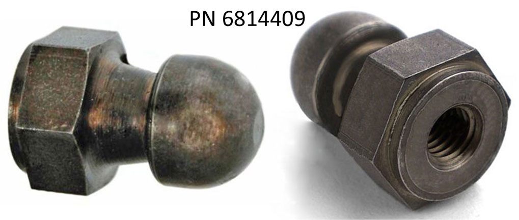 Volvo PN 6814409 (tall pivot) is listed by Volvo Classic Restoration as for 1979-92 cars. classicvolvorestoration.com/pivot-pin-clutch-fork-240-79-92 Volvo PN 3549638 (short pivot) is listed for 1993 and later cars. classicvolvorestoration.com/pivot-pin-clutch-fork-volvo-240-74094093 I think you could probably use either type for a 240. If it needs to be longer, a spacer or washer can be placed under it. The threaded hole in the rear is M8-1.25. And then there's this mystery pivot ball I used years ago. It's from Volvo, however I don't have more info. 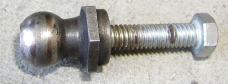 |
|
|
|
|
| When I first installed an M46 in my 240 and then later a T5 I used a CABLE Type Clutch Fork, so I'll show that first. The standard Volvo clutch fork is used with a Ford Mustang style clutch release bearing. The fork required some special metal pieces to be added to properly support the Ford T5 bearing. These are really old photos below from 2004. 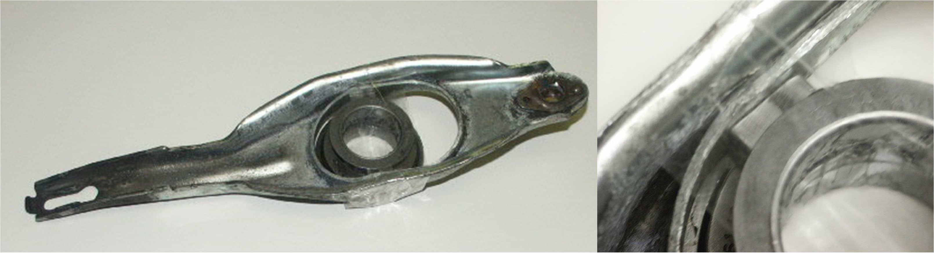 Here are some better photos below of the new parts that are offered by BNE Dynamics for a cable type fork. 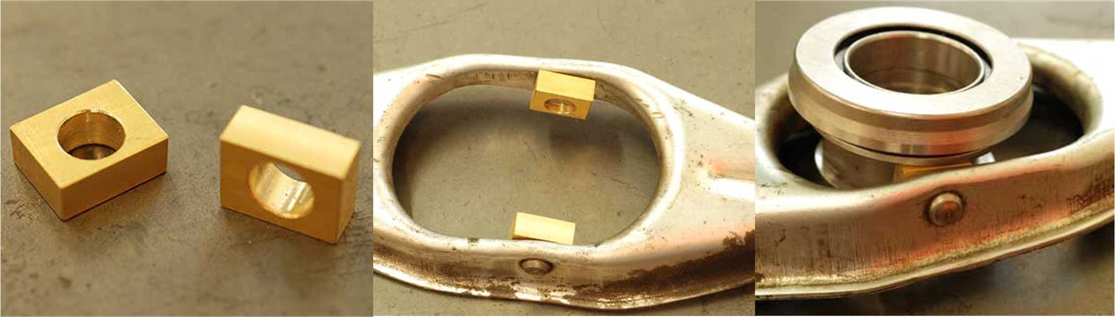 These special pieces are available from BNE Dynamics: bneshop.com/throwout-bearing-for-t5 The McLeod 1600 release bearing (throw-out bearing) is equal to the standard Ford T5 bearing. The McLeod 16515 is an alternate adjustable version you can find in the BNE page. Either of these bearings can be used with a Ford T5 in a Volvo for use with a cable fork or hydraulic fork. 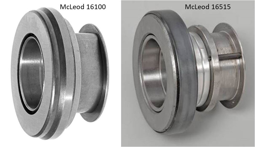 The adjustment instructions for the adjustable type are found here: https://www.mcleodracing.com/product_images/mcleodracing/installation_instruction-instruction_file-118-v1.pdf Comparison: Cable versus Hydraulic Clutch Fork. The top clutch fork is a typical cable type. The bottom one is a typical hydraulic type from a 740. Any typical 740 clutch fork is perfect for this project. Volvo 740 part numbers that should work: 3549983, 1220763. 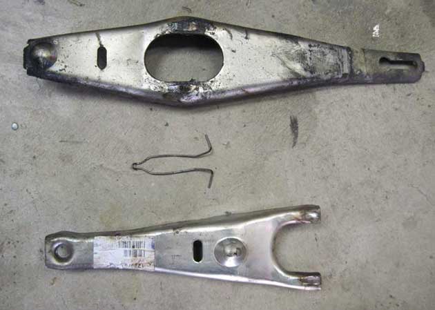 CLUTCH FORKS FOR HYDRAULIC This is Volvo PN 1220763, which was made for Volvo 740 or 940 models. This one has a HOLE in the slave cylinder end. 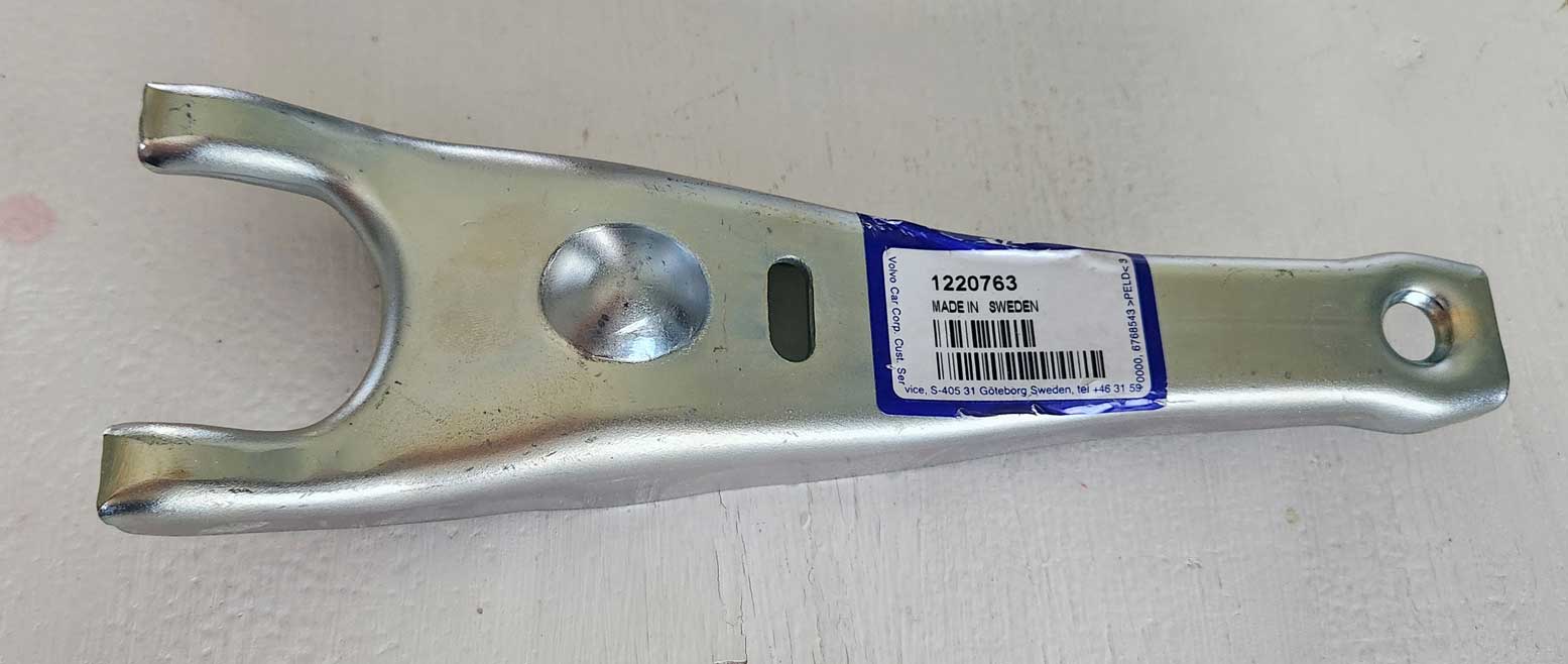 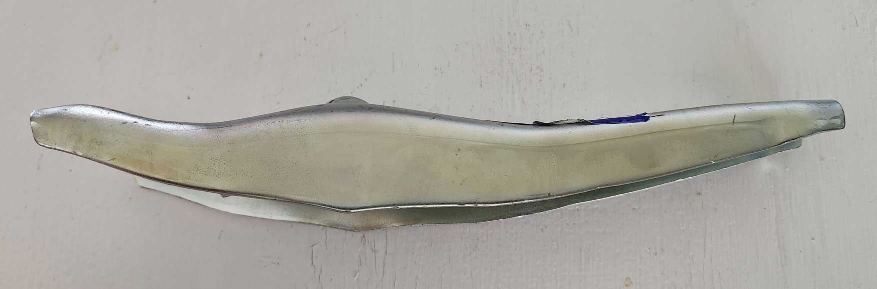
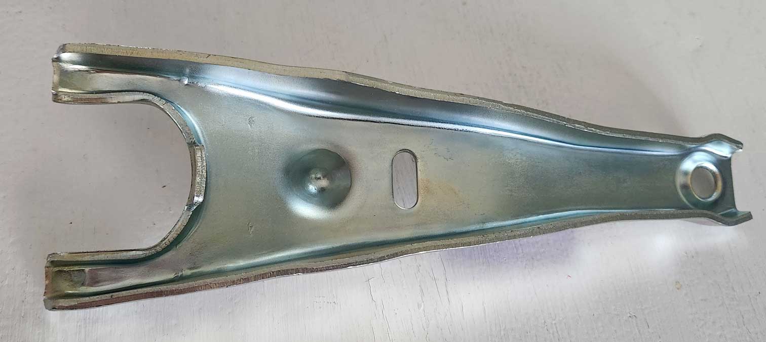
ALTERNATE FORK There is an alternate fork available which has a depression on the slave end instead of a hole. This is the fork used with M90 trans equipped 940s. Volvo PN 3549983. 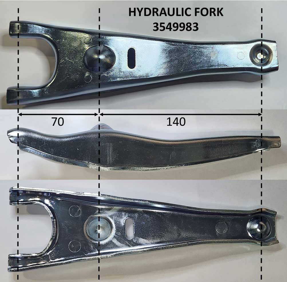 |
|
|
|
|
|
For my project I bought a used Volvo 260
hydraulic clutch pedal and fitted it into my
existing manual trans pedal box.
A hydraulic clutch pedal is about 50 mm longer than the cable style pedal (between the pedal and pivot) because it mounts into a different set of holes in the pedal box that are higher in the box. The holes for a hydraulic pedal should already exist in the pedal box.  Ignore the bend above. That was done before I got it and it's not like that originally.  And here's the CABLE style pedal for comparison. 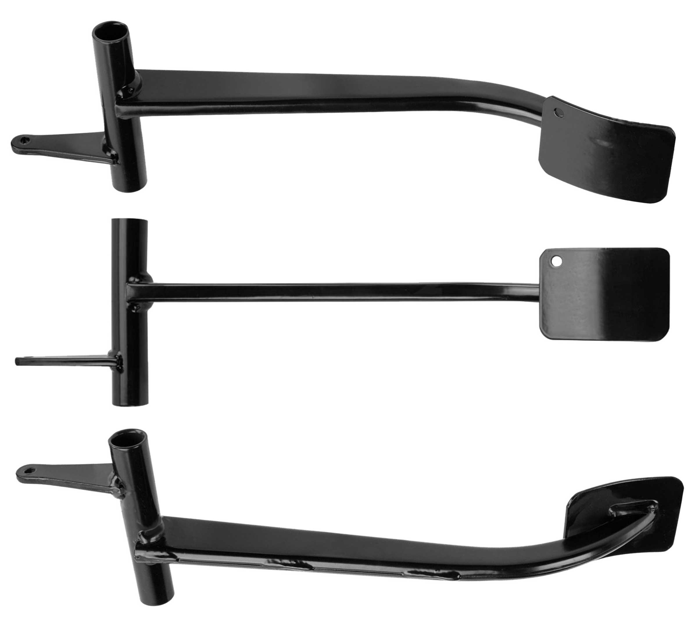 Pedal ratio differences between Cable type and Hydraulic type. Source for dimensions: https://turbobricks.com/index.php?threads/366388 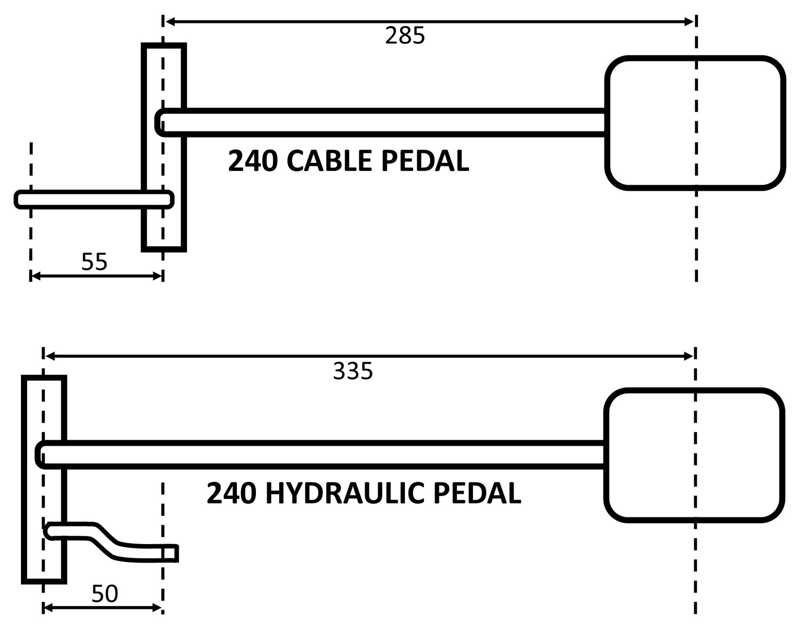 |
|
|
|
|
Here is where
the holes are found for mounting a HYDRAULIC
pedal. It's mounted about 2 inches higher up in the pedal box.
|
|
|
| |
|
There are some Turbobricks threads in which
people have made their own hydraulic pedals or
they have modified a cable type pedal to work. That sort of work was beyond my
skills.
Here's a thread about one that was custom made: turbobricks.com/not-mediocre-242.326370/page-6
|
|
| As of 2018 STS Machining is offering a custom new aluminum 240 hydraulic clutch pedal. 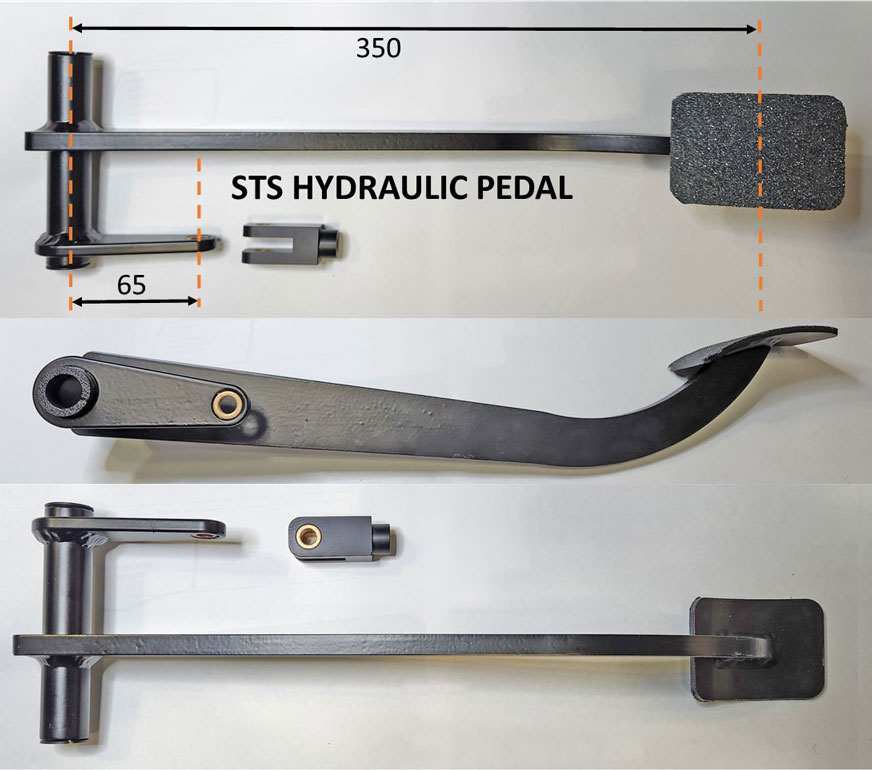 The clevis below has a threaded hole for a push rod with 5/16-24 thread pitch. This is a standard thread for push rods that will usually come with aftermarket clutch master cylinders, such as those from Tilton or Wilwood. 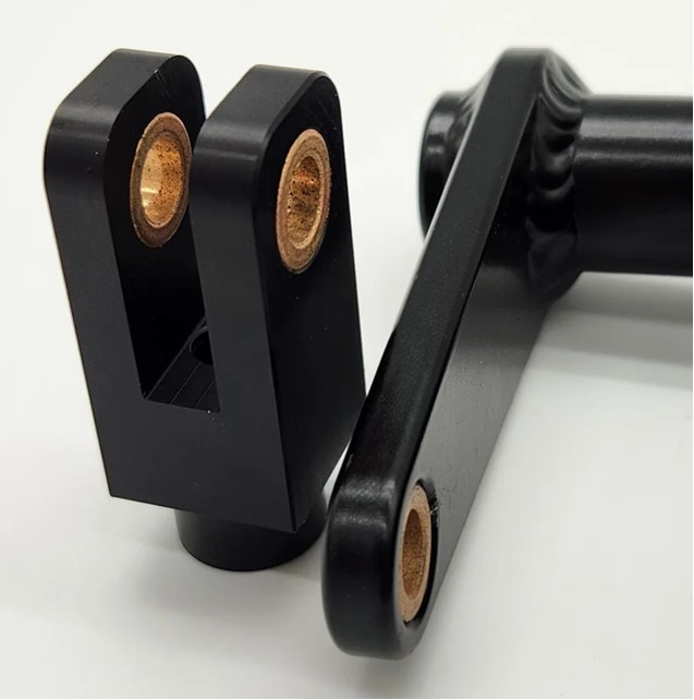 |

| 2017: Changing from a Volvo FAG to a different Master Cylinder |
|
After about 6 years of use, the new Volvo 260 master cylinder shown here began to
fail. The piston seal began leaking fluid
out of the back when pushing on it.
This might have been due to the heavy clutch I had, but it could also have been because this was a 30 plus year old NOS part when I bought it. I could have rebuilt it, but I thought the chance of this happening again was probably high. So I decided to try a different master cylinder. There are a number of choices. I'll show you a few I considered below. Whichever master cylinder you choose, be sure to consider the inner piston size. Most aftermarket master cylinders will give you several size choices. The Volvo Fag 260 MC has a 0.75 inch (19 mm) inner piston. That's the size I would be looking for initially (but if you read further down, you'll find out I later changed my mind for my clutch situation). |
||||||||
|
|
||||||||
 The MC is certainly short enough to fit in a 240. It's very similar to early Volvo master cylinders used in Volvo 122 Amazons. I did not prefer the hose outlet being on top like this. It makes bleeding more difficult than something with a hose sloping downward toward the slave cylinder. When bleeding a hose that rises above the master cylinder, air will get trapped in there. So when bleeding, it can be hard to get that air out. If you have someone pushing the pedal while you're under the car opening a bleed valve, it can be frustrating. This can more easily be solved with a power bleeder, which is shown further below. A power bleeder has the ability to push a lot of fluid through the hose under constant pressure to overcome an air bubble. If I had chosen a master cylinder like the Wilwood shown above, an alternate solution would be a 90 degree fitting on the outlet for the hydraulic hose or maybe a banjo fitting similar to the below images. 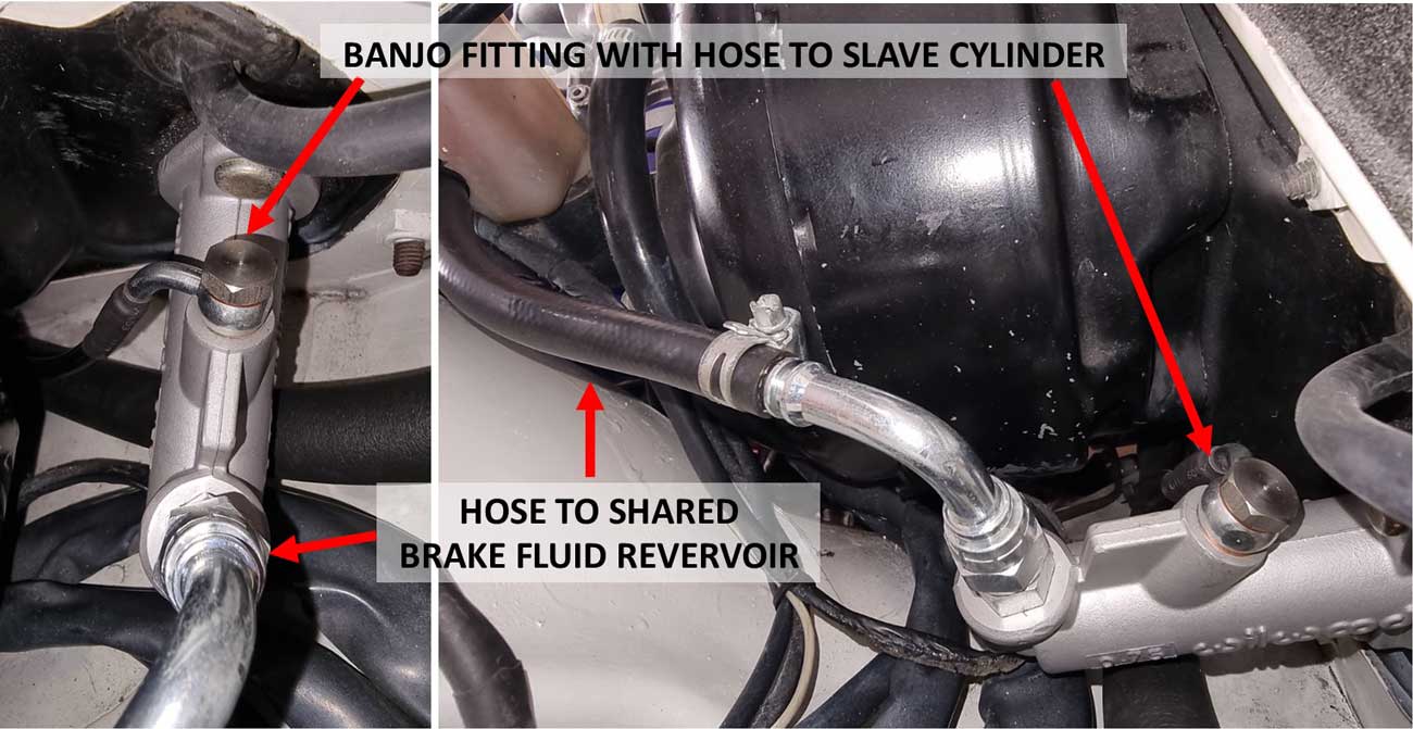 Here are a couple images above from Aris 240 (from Greece). In 2023 he installed this Wilwood Compact Remote master cylinder PN 260-6089 for his clutch. It's made for a remote reservoir and in this installation it shares fluid with the brake fluid reservoir from a 740. Aris' 240 build info is detailed in the following forum discussion (go to Post #136): https://turbobricks.com/index.php?threads/the-build-story-of-a-greek-hopefully-fast-240-brick.310632/ A benefit of this style of master cylinder is that it offers a stroke of 1.4 inches (35.5 mm). This is more than the Volvo FAG 260 MC, which has a stroke of 1.3 inches (33 mm). Volume area: 0.57432 sq.in. |
||||||||
|
|
||||||||
|
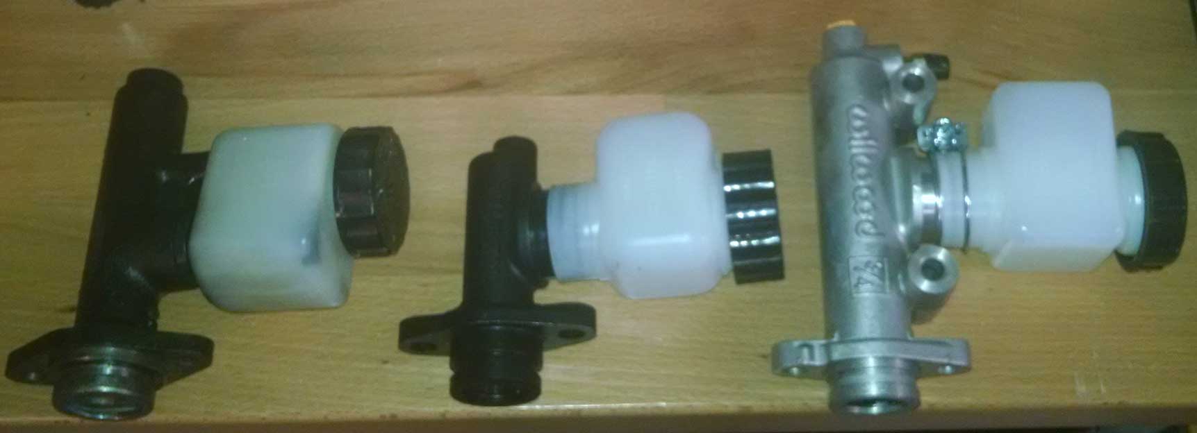
The TILTON 75 compact MC (shown below
MIDDLE) only has a 1.1 inch (28
mm) stroke. With bore of 0.75 inch, the volume area is 0.48597 sq.in.
Most MCs from Tilton or Willwood can be ordered with a few different
bore sizes. I later found the shorter STROKE became a problem for my car.
You'll see if you keep reading.
|
||||||||
| I chose the Tilton
75 Series below with a .750 inch (19 mm)
piston bore. While installing it I discovered that there was a new problem. There always is, isn't there. The 240 firewall sheet metal (just above where the master cylinder mounts to the firewall) interfered with the reservoir. It's because the reservoir on this style master cylinder is positioned very far to the rear and you can see it's very close to the firewall mounting flange. Basically the reservoir hit the firewall before the mounting flange did. PHOTOS coming up further below. 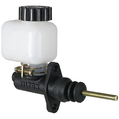 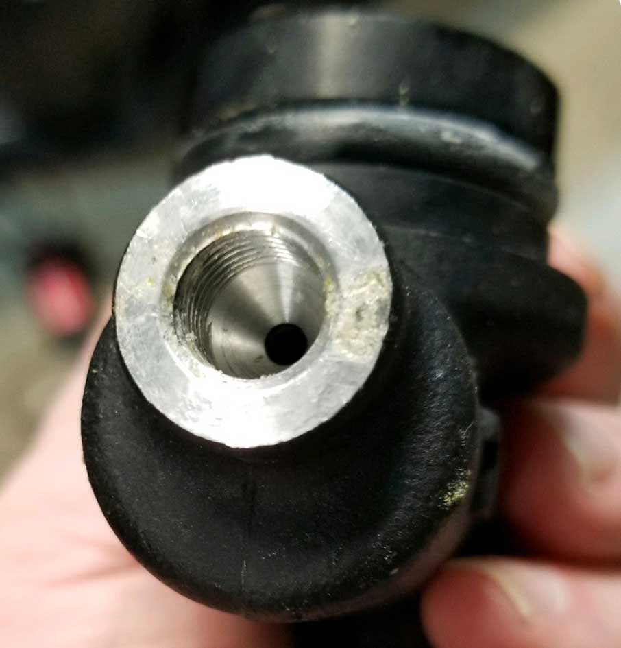 The outlet port is threaded for 3/8-24 female, which is the same as AN -3 thread. 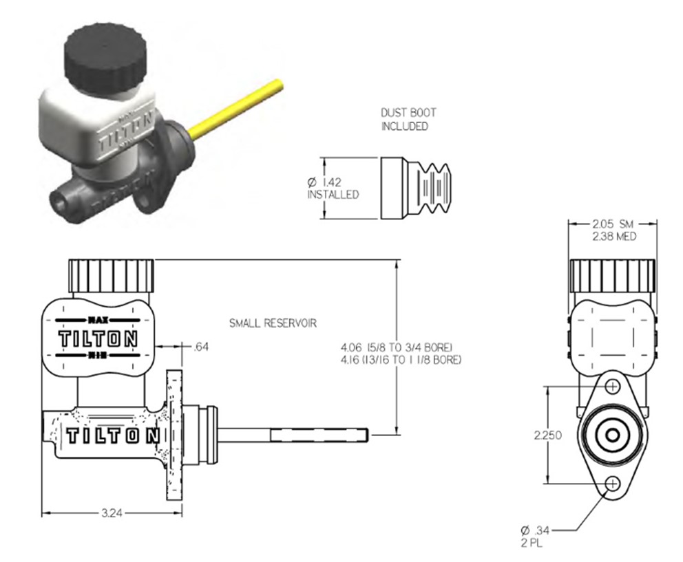 |
||||||||
|
|
||||||||
| I NEEDED TO FIX THE FIREWALL
CLEARANCE PROBLEM with SPACERS: So my solution was to use a couple 1/2 inch thick round spacers and some longer bolts I had on hand. Not the most elegant solution, but it gets the job done just fine and the mounting at the firewall is still very solid. Problem fixed. I had originally hoped to find a 1/2 inch spacer shaped similar to the mounting flange so I could move this master cylinder 1/2 inch forward. Such a spacer did not exist when I was searching and making one was too much work. 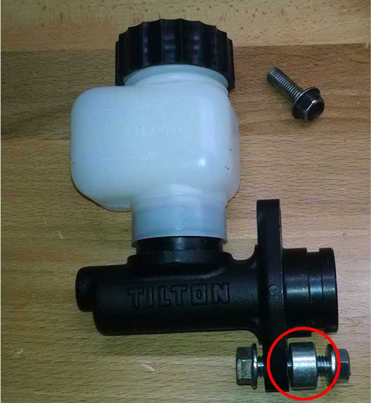 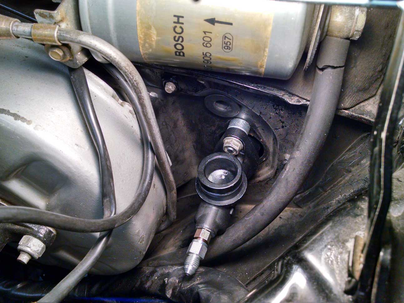 |
||||||||
|
|
||||||||
| Then it was time to have the new hose made. I took the master and slave cylinders down to a local hydraulic hose shop, along with the adapters that came with the master. Keep in mind that most hydraulic hose shops are there to make hoses for heavy equipment. They may not be experienced with automotive or hot rod stuff. 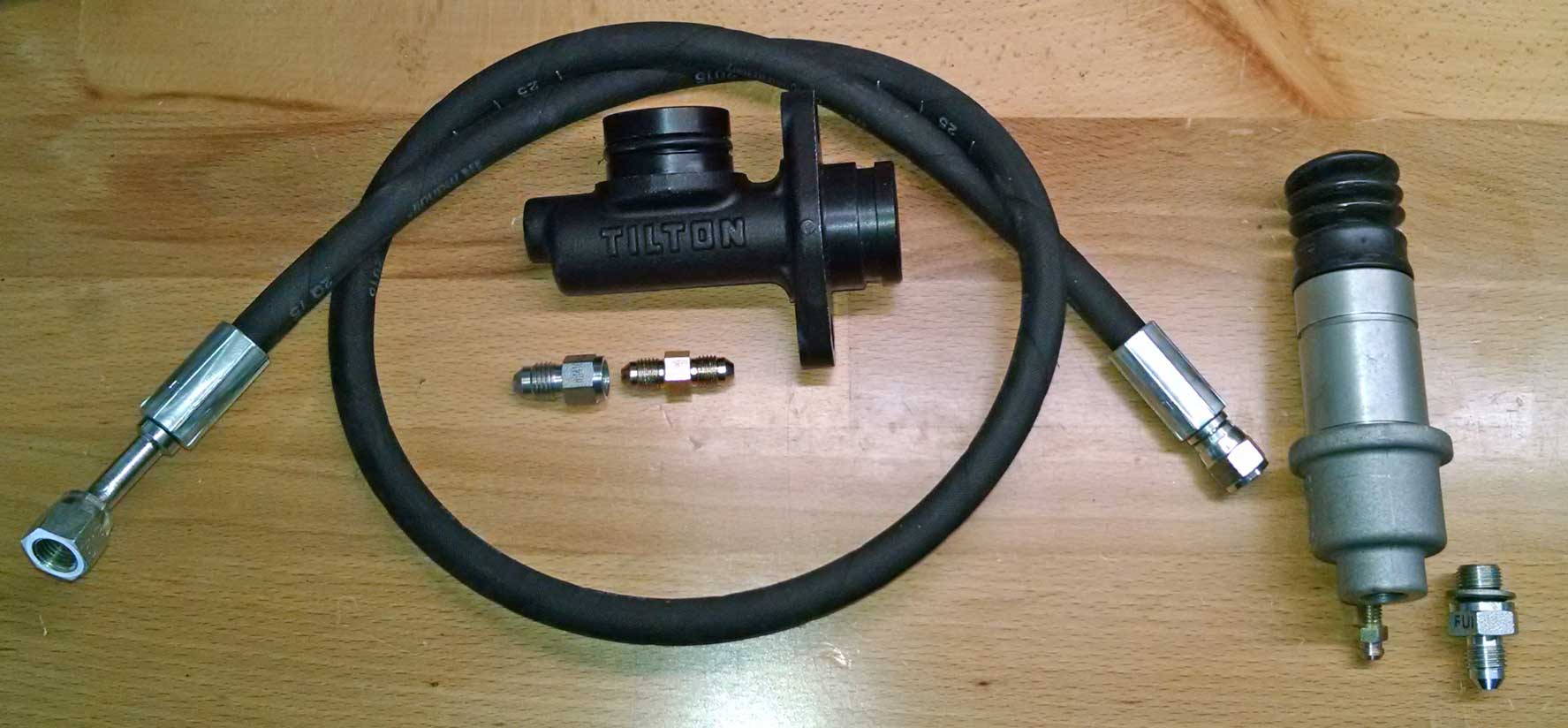
There are a number of ways to make a hose for these components. Lots of options exist. If you know specifically what fittings YOU want, discuss that with them. Try to be patient and have as much info for them as possible. Hose detail: fitting to the Tilton Master Cylinder: The Fag-Volvo 260 MC I previously used and the 740 slave cylinder both have a port with thread pitch of 12 x 1.0 mm female. Now I have an MC with a completely different thread. This Tilton MC has 3/8-24 female threads (which is the same as an AN-3 racing hose fitting). The port outer face is machined flat in case you want to use a banjo fitting or an AN -3 fitting which uses a sealing washer. Those are options to consider. I went a different route.
The Tilton MC came with some adapter fittings. One was that gold-colored fitting in the photo above (double male AN-3 flare fitting). The hose shop I went to had commercial JIC fittings and high pressure -4 Golden21/ISO 3000 psi flexible hose. They used that gold AN -3 double male flare fitting along with another adapter fitting they supplied, which stepped up the AN -3 to AN -4. Then they mated a new hose end to the AN -4 hose. This new hose end was a 45 degree JIC (AN -4) female swivel fitting, which can be seen above. That completed the master cylinder end. Fitting to the 740 Slave Cylinder. On the slave cylinder the port is threaded 12 x 1.0 mm. The hose shop supplied a Male JIC 7/16-20 (equal to AN -4) to 12 x 1.0 mm O-Ring adapter, which is shown below. The 12 x 1.0 mm end goes into the clutch slave. The O-Ring I used to seal this was a metal-bonded sealing washer. The above adapter would then mate to a new hose fitting they crimped onto the AN -4 flexible hose. This new hose fitting was a JIC 7/16-20 (equal to AN -4) STRAIGHT female swivel fitting, which can be seen in the hose photo above. The total length of the new hose when completed was about 36 inches. Cost was about $60.
|
||||||||
|
This is a metal-bonded
sealing
washer.
It has a rubber o-ring embedded in it. It's generally used where a flat sealing washer is required or when a flare fitting is not used, such as on the M12 end of this adapter above. McMaster Car has them: mcmaster.com/#standard-washers, click "Sealing Washers," then "Metric High-Pressure Metal-Bonded Sealing Washers." Your local hydraulic hose shop may have them too. You might be thinking this hybrid washer above is inferior to an all-brass washer. You would be wrong. It can handle thousands of PSI and will easily out-perform the sealing capability of an all-brass washer. |
||||||||
|
|
||||||||
| This factory clutch push rod clevis needed some adjustment. This push rod is listed in early 240 parts catalogs as PN 1221931. For my use I found I needed to shortened the rod almost 1/2 inch compared to when it was used with the 260 master, even with the 1/2 inch MC spacers at the firewall shown above. The threads on this thing allow for a small adjustment, but for the length I needed, that forward rod had to be shortened a small amount (maybe 1/8 inch) using a bench grinder.  If you need to source a clevis pin for one of these, the hole ID is 8 mm. The outer width of the clevis at the hole is 14 mm. This original fastener on my factory 240 clutch pedal was a grooved 8 mm clevis pin with an 8 mm clevis spring clip (BELOW). 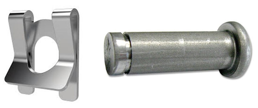 However, you may optionally use a standard clevis pin with a hole and a hitch pin (BELOW). Volvo also shows in parts catalogs they used used this as PN 964843 for the clevis pin (other PN: 913100, 964821). 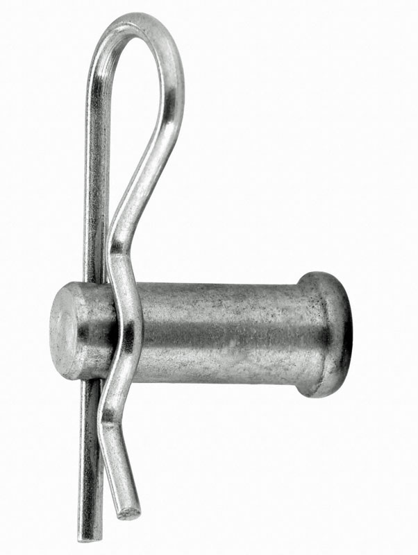 |
||||||||
To those of you who didn't believe me that
spacers were THAT necessary to fit this master
cylinder/reservoir combo, have a close look at
this photo. Yes,
that is the master cylinder WITH 1/2 inch spacers installed.
The reservoir cap is almost touching the firewall.  |
|
|
|
|
|
Update: June 2017
ANOTHER Master Cylinder Change. PROBLEM: The piston stroke for the
Volvo 260 FAG master cylinder is about 1.3 inches (33 mm). Volume area of the FAG with 0.75 inch (19 mm) bore was 0.57432 sq.in.
The Tilton 75 Series MC with 0.75 inch bore has a stroke of only 1.1 inch (27.94 mm). Volume area is only 0.48597 sq.in. This presented a problem in my car and it turned out I was not getting as much pedal stroke (not enough fluid volume) when pushing the Tilton master cylinder as I was before with the FAG MC. So after installing the first Tilton MC, the clutch wanted to disengage very close to end of the pedal travel near the floor. I didn't like that. I needed a bit more hydraulic stroke in the pedal travel, but the Tilton 75 master cylinder is not available with a longer stroke. 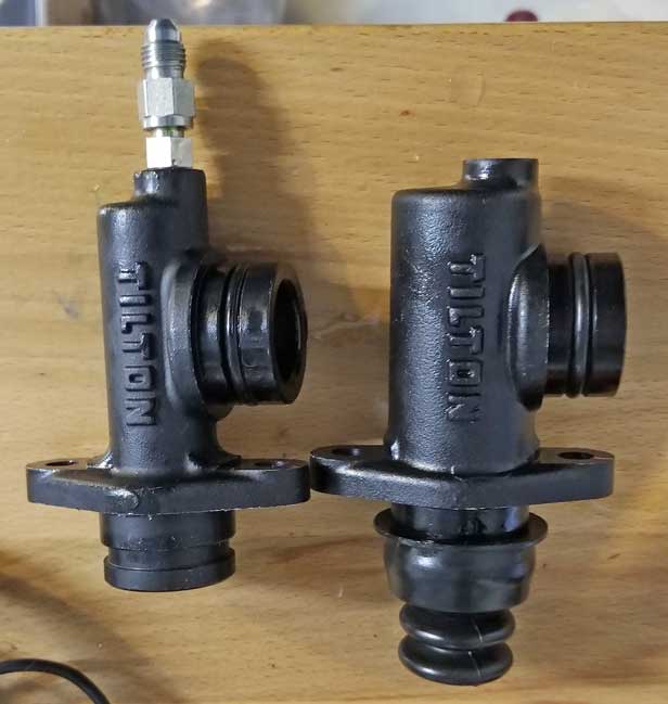 The Wilwood version of this MC is the exact same design as Tilton. No difference. So my decision was to change to a Tilton 75 with a larger bore SHOWN ABOVE RIGHT. This one has a 13/16 inch (20.64 mm) bore instead of 3/4 inch (19 mm). New volume area with 1.1 inch stroke: 0.58802 sq.in. Adding that extra 1/16 inch bore (1.59 mm) seems to add about 17% more fluid volume in the piston stroke. This volume increase is equal to increasing the stroke from 1.1 inches to about 1.3 inches, which virtually gives it the same volume as the Volvo FAG master, which had 0.57432 sq.in of volume. That corrected this problem for me. If you need a master cylinder like this with a different bore, Tilton offers them with 5/8 inch, 7/10 inch, 3/4 inch, 13/16 inch, 7/8 inch, and 1 inch. More about how to navigate this kind of issue is presented pretty well in this video from DazeCars. https://www.youtube.com/watch?v=m0bMac1-McQ |
|
|
|
|
|
MOTIVE POWER BRAKE BLEEDER
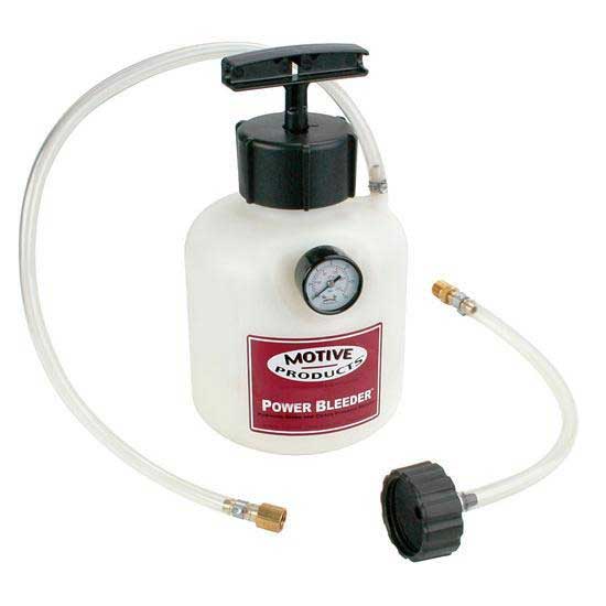 When it comes time to bleeding brake or clutch hydraulics, nothing I have seen beats the Motive Power Bleeder. This it has served me well for years and years for brakes and clutches. DIY bleeding with no need for a helper. Perfect. NOTE: If you need a reservoir cap with a pressure nipple in a pinch, I use an extra cap I bought that fits the reservoir, which I drilled and installed a brass nipple. Make one of those ahead of time and keep it with your power bleeder.
RESOURCES: AN Thread Wikipedia: https://en.wikipedia.org/wiki/AN_thread Automotive Fittings Explained: http://www.speedwaymotors.com/the-toolbox/automotive-fittings-explained/28780 Useful discussion threads: turbobricks.com/wilwood-clutch-master-cylinder-for-my-242.100636 turbobricks.com/making-your-cable-clutch-hyrdaulic-in-your-240.149175 turbobricks.com/240-hydraulic-clutch-conversion.234399 turbobricks.com/critique-my-hydraulic-clutch-set-up.325285 turbobricks.com/converting-cable-trans-to-hydraulic.320417 But if you're one who's stuck on the pedal push bleeding method, here's a video that will help. It involves clamping the slave cylinder closed (compressed) so it doesn't extend on you during your pedal pushes. Good luck. https://www.youtube.com/watch?v=Vwjrh4ezwdU |
 Swapping the pedal box can be a pain, but it's so necessary for this stuff. If you have time, I prefer removing the dash so access is so much easier. It can be done without doing that, like this write-up, but it can take some extra patience. This write up in TB shows how this swap was done from auto to a manual pedal box (with hydraulic clutch) in a 1991 240. turbobricks.com/hydraulic-manual-swap.372737/ |
|
Back in 2009 (before I fitted a hydraulic clutch) I thought my
clutch cable must be stretching because my clutch kept
going out of adjustment. I thought it
might snap in heavy traffic somewhere, so I got a new
cable and pulled out the old one. When I compared the two
side-by-side, they were identical in length. No
stretching to be seen.
|
|
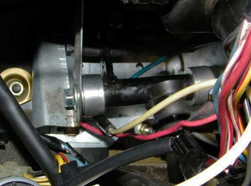 ABOVE BELOW: I could see that the metal framework for the pedal box was becoming seriously bent and deformed. The pivot for the clutch pedal was slowing being pushed closer to the firewall. This explains why clutch engagement kept moving closer to the floor, making it seem as though the cable was stretching. |
|
|
|
|
After I pulled out the pedal box, I could see the
damage more closely. It was pretty seriously bent. 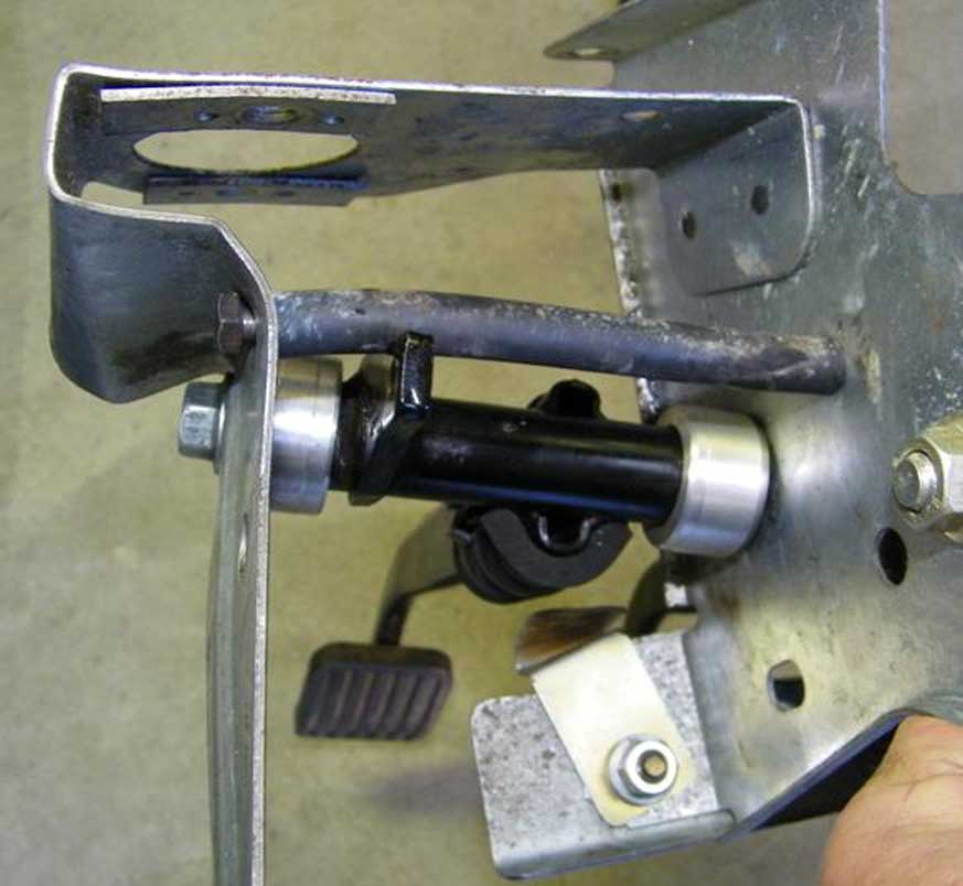 This is what a STRAIGHT or UN-BENT box looks like. 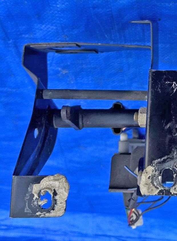 |
|
|
|
|
So
after straightening the metal walls, I needed to
reinforce the metal to keep it from doing that again.
You can see here I added some thin steel sheet metal
to strengthen that side wall. 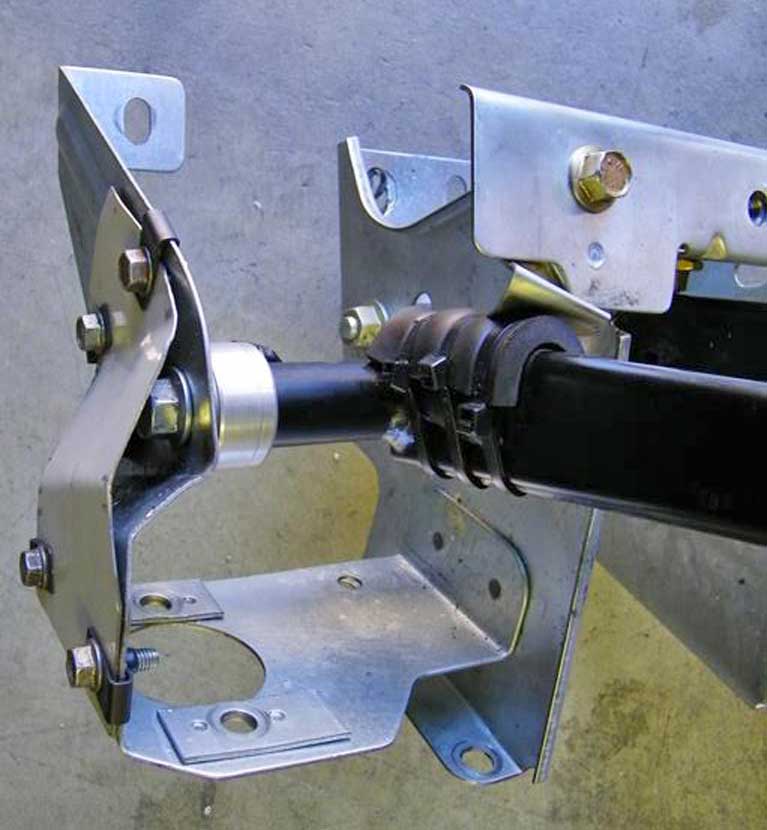  I wanted it to be removable in case it needed to be worked on later. So welding it was not an option for me. I used some clip-on barrel nuts (also known as U-nuts), which I got from McMaster-Carr. PN 95210A150. Thread pitch is metric: M6 x 1mm. These are made for a panel thickness of 0.8 to 4 mm. The bolts I used are typical metric bolts with a 10 mm hex head that you'll find in your 240. If you don't have any, McMaster- Carr does: PN 98093A436, M6 x 1mm, 16mm long with flange head.  |
|
|
|
|
|
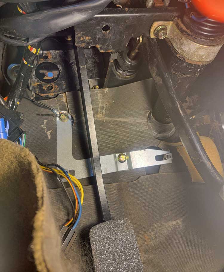
Then in 2013 (after switching to hydraulic)
while pushing in the clutch pedal I felt a SNAP. Then the clutch pedal was suddenly very crooked as you can see here. 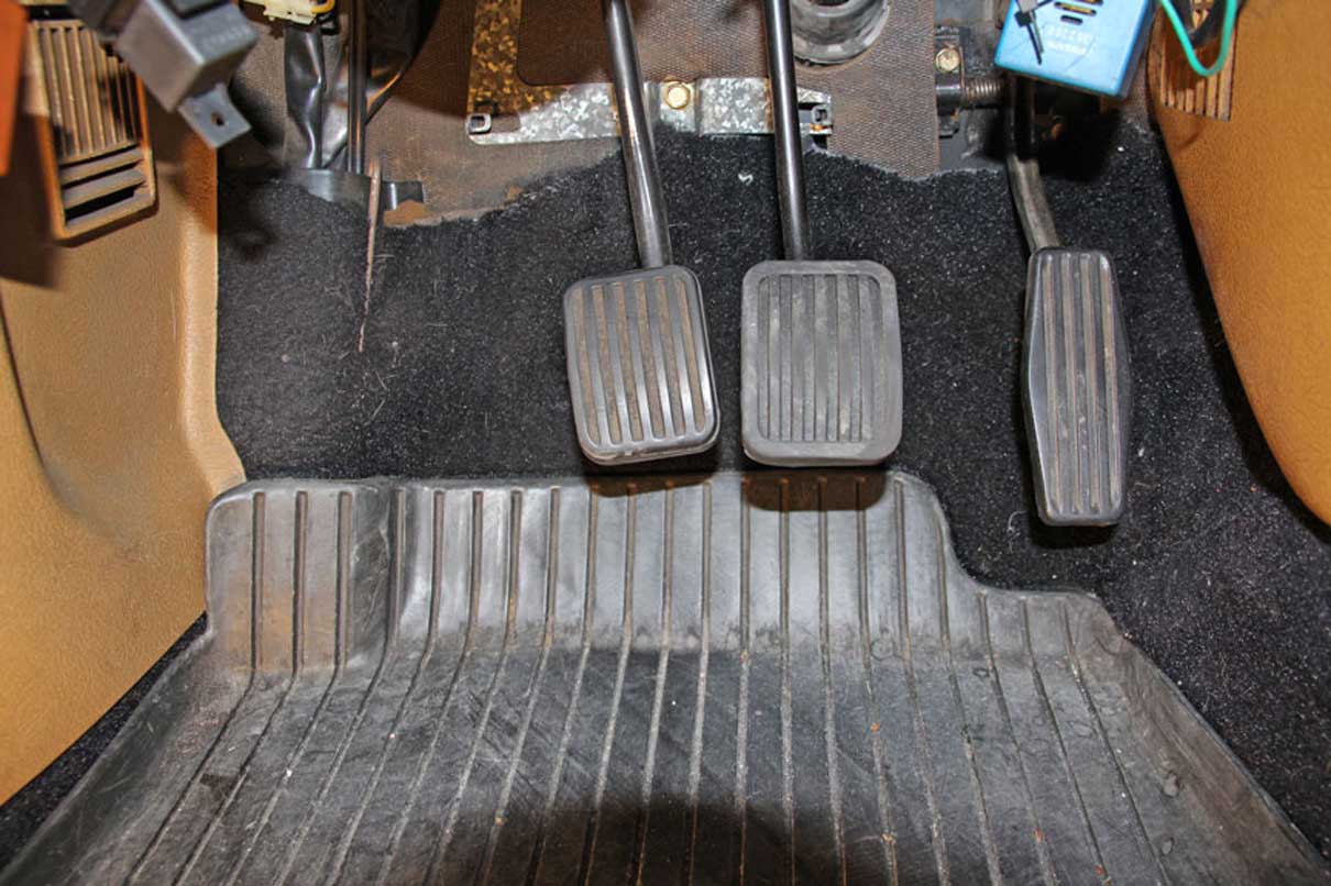 |
|
|
| |
 After pulling out my instrument cluster, I could see this welded captive nut in the cowl above the pedals had been ripped out of the cowl sheet metal. |
|
|
|
|
I didn't have a
welder (or welding skills) and I didn't want to take the car somewhere to be
welded after pulling it all apart. So I removed the dash and AC vents and I made a steel plate and carefully bent and fitted it so it would fit up
under the cowl nice and snug.  I took the plate to a welder and had that nut welded on. |
|
|
|
|
Then I
drilled some holes (more than needed) and inserted threaded inserts, which I bought on-line,
so it could be bolted VERY SECURELY to the cowl and it would be
SUPER STRONG.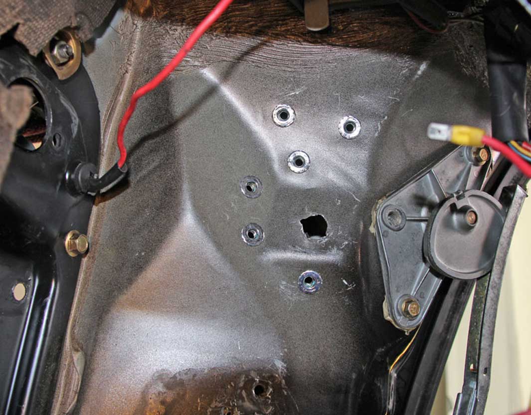 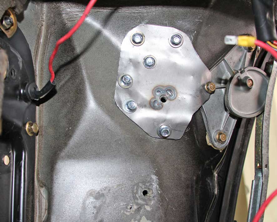
|
|
|
|
|
 Here's the pedal box I was using on the RIGHT that got BENT. The new bend near the firewall mounting part happened when that captive nut broke out of the bottom of the cowl. But since these pedal boxes are not really what I would call sturdy when new, I decided to do another BETTER job of reinforcing it before putting it back in. |
|
|
|
|
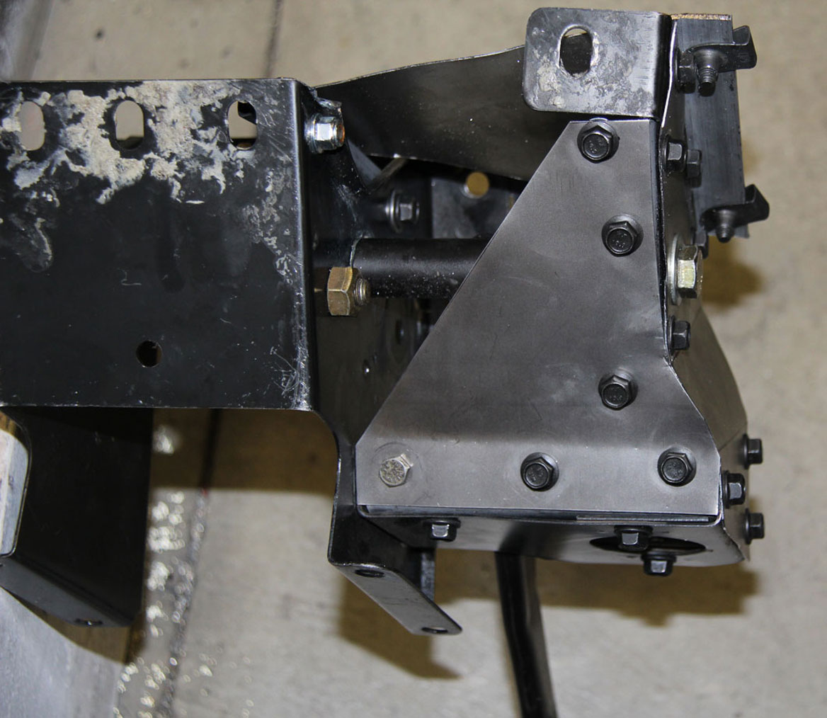
Here we
go. I added new and MORE bracing this
time. I wanted a VERY STIFF pedal box.  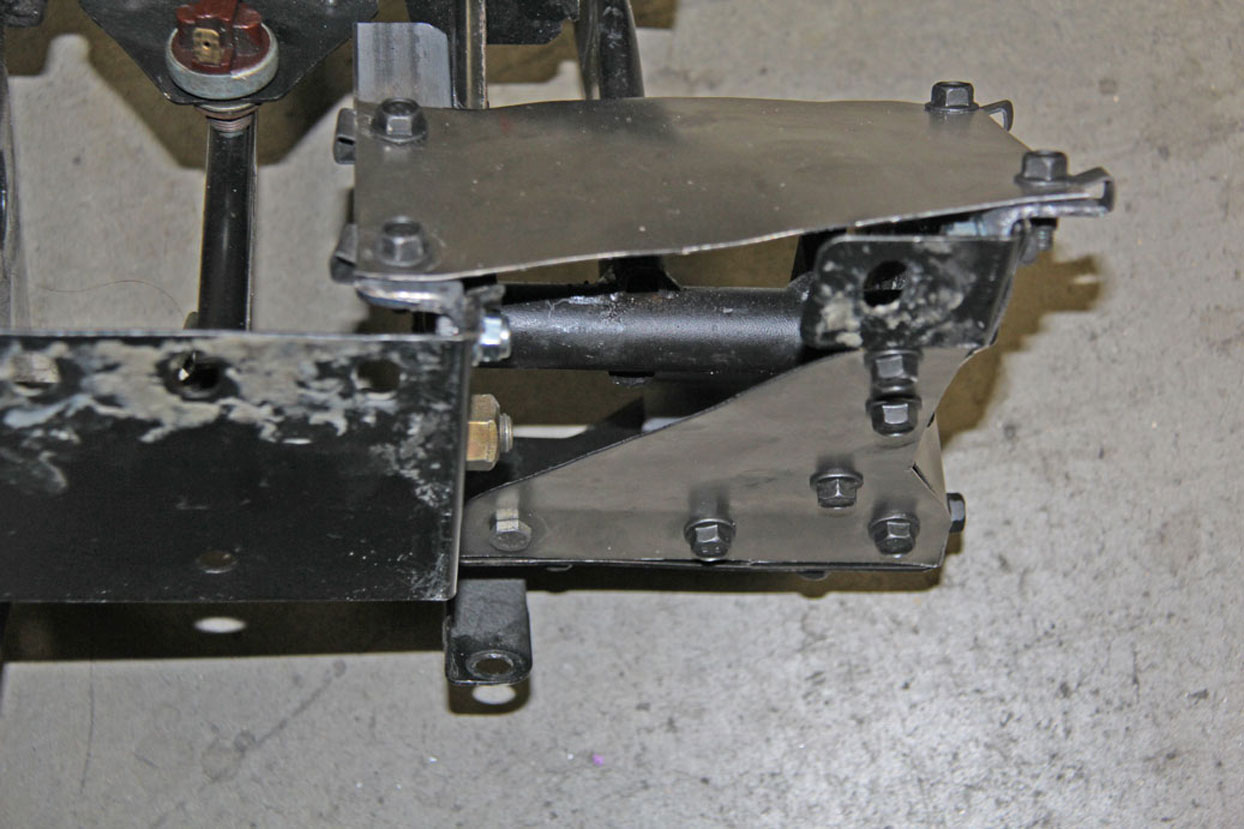
|
|
|
|
|
|
|
|
|
|
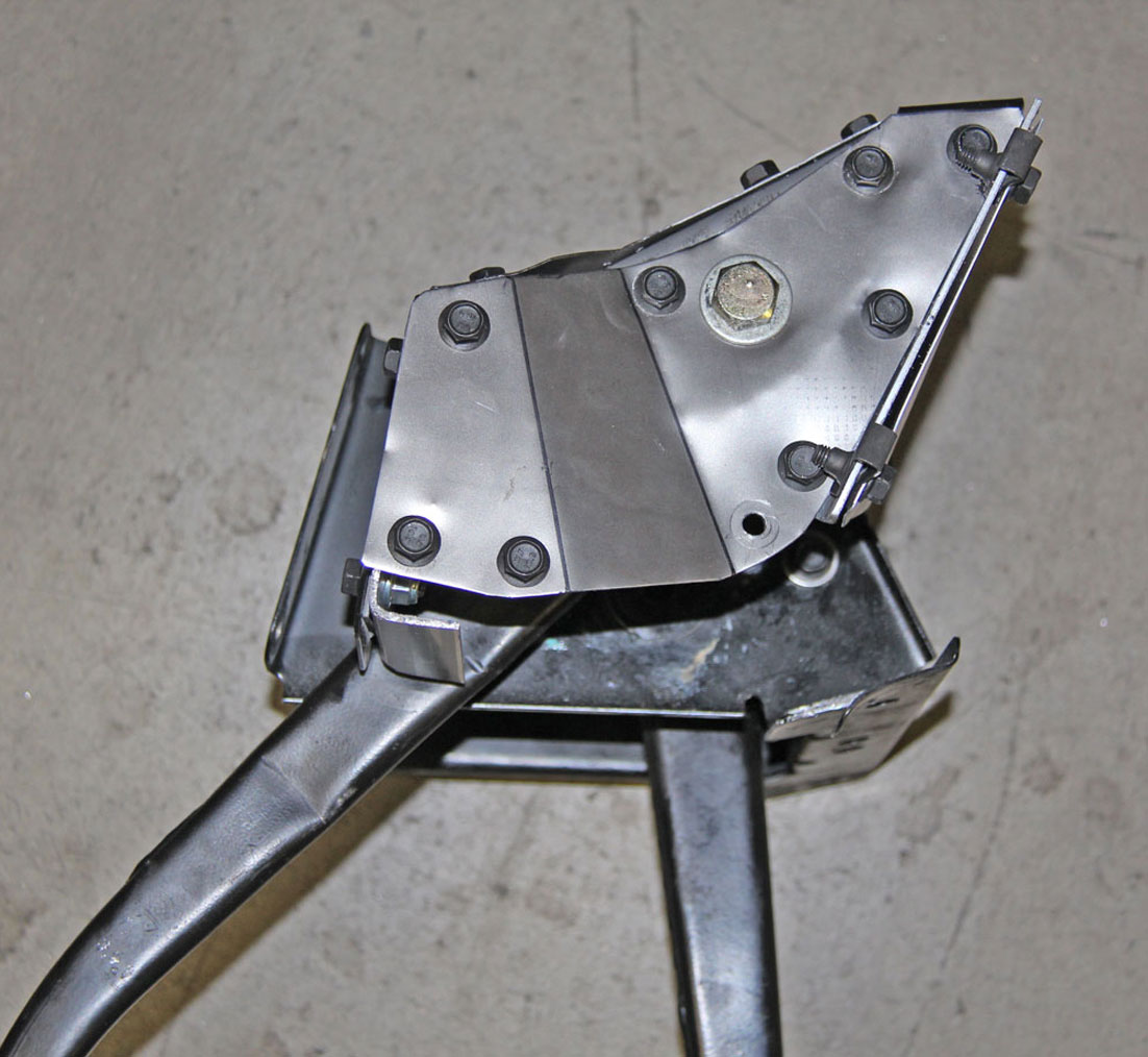
 This view is of the back side that faces the driver. That plate comes off before installing the pedal box, since there are firewall fasteners that you need to reach behind it. Then that plate can be re-installed. This plate is overkill and probably not really all that necessary. But I'm hoping overkill is just what's needed to keep me from having to take the pedals out again. |
|
|
|
|
 Here is an in-progress photo looking through the instrument cluster opening. The newly reinforced pedal box is being bolted in and that removable plate has been removed. |
|
|
|
|
Here I have
completed the installation and the front plate has
been installed.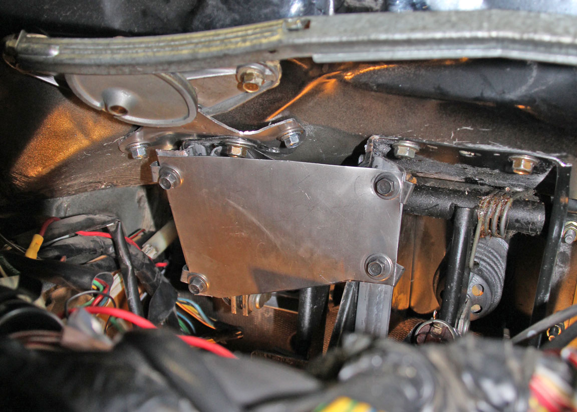 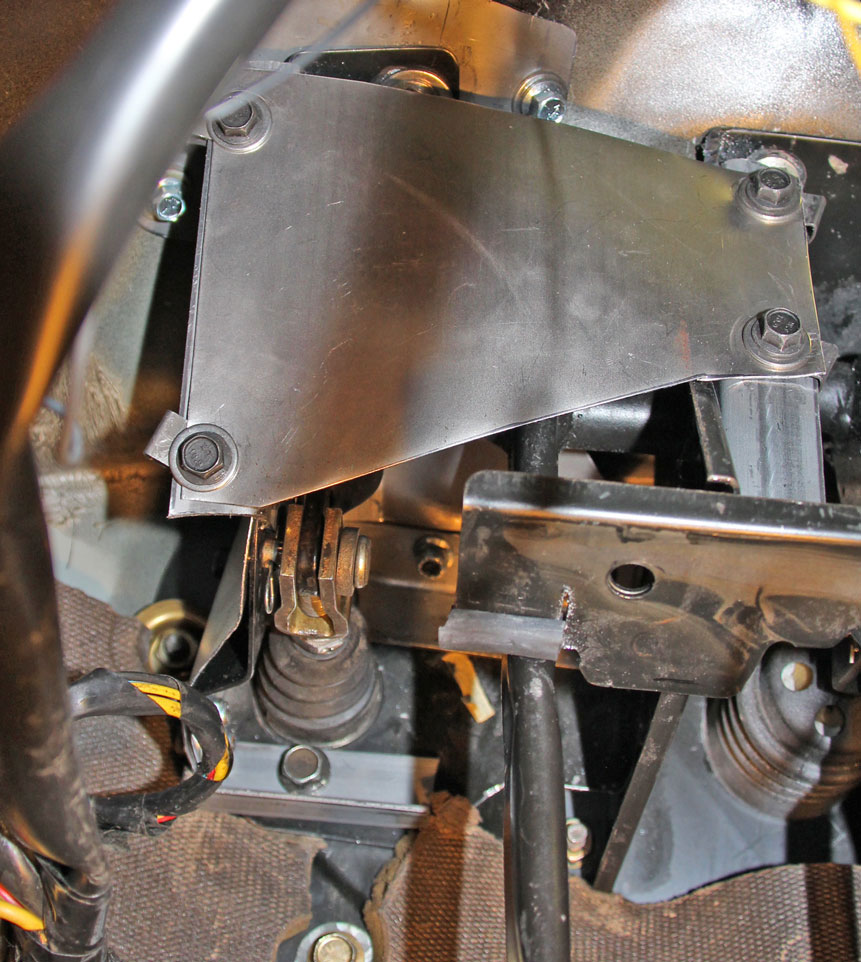 The result is a super stiff and super strong pedal box. Hopefully this info will help someone else from having a similar problem in the future. |
|
|
|
|
|
||||
| davebarton.com |
prancingmoose.com |
240turbo.com |
Special Emblems |
|
| Prancing
Moose Stickers |
Volvo
Stickers |
Body/Chassis/Engine
Labels |
240 MODS and FIXES Page | |
| Other Car Brand
Stickers |
Steering
Wheel Labels |
Center Cap Labels/Overlays |
Cool Volvo
Products |
|
| Grill Labels/Overlays |
Volvo Wire
Harnesses |
Conversion Harnesses |
Harness
Parts/Connectors |
|
| Volvo Relays |
Coil Repair
Harnesses |
240 Window
Scrapers |
740/940
Window Scrapers |
|
| Adjustable Voltage
Regulators |
Horn Buttons |
240 Odometer
Repair |
740 Odometer
Repair |
|
| Volvo Gauge
Faces |
740
Turbo/Boost Faces |
240 Black Door Vinyl |
850 Odometer
Repair |
|
| ALTERNATOR Page |
240 Power Mirrors - Switches |
240 Oil Cooler Page |
240 Fuse Panel Page |
|
| Group A
Racing 242 Turbo Page |
240 Hydraulic Clutch | Fuel Pump RELAY Page |
240 Headlight RELAY Page |
|
| Used Parts & Extra Stuff for sale |
CRIMPING Page |
240 Ignition Page |
240 Headlight Page |
|
| 240 Gauge Electrical Diagrams | 240 REAR END Page | Yoshifab Catch Can Install | 240 TAILLIGHT Page | |
| Side Marker
Lights Page |
Gentex Mirror Upgrade | Yoshifab Drain Tube Install | Modified 240 Favorites | |
| SoCal Salvage Yards | Unleaded Racing Fuel | B26FT Stroker | Dave's 245 Spec Page | |
| 240 SUSPENSION Page | 240 Lowering Page |
240 Windshield Page |
240 WIPER Page | |
| 240 BRAKES Page |
240 Dash Top Gauge Pod | Cadillac 4-Note Horn Install | 240 DYNAMAT Installation | |
| 4 Speed Fan
Controller |
Electric Cooling Fan
Page |
BRUSHLESS Cooling Fan Page |
Tropical Fan
Clutches |
|
| 240 AC Page | "KOMFORT BLINKER" Upgrade | T5 Trans Conversion Page | 240 Engine Mount Page | |
| 240 VIN Page | Stepper Idle Valve Page |
Vacuum Diagrams | 240 HOOD Page | |
| 240 Exhaust Page | 242 Power Vent Window Project |
EFI Volvo Pin Function Diagrams |
Favorite Links | |
| R-Sport
Apparel |
Prancing
Moose Apparel |
Volvo Meet Photo Albums | Texas Volvo Meets and Events | |
| Ordering Instructions | Policies | PAYMENTS Page |
Mojave Road Trail Map Page |
|
| Returns | Shipping | Shopping Cart Troubleshooting | Contact Us |
|