|
2 4 0 T U R B O . C O M D A V E ' S V O L V O P A G E
|
||||||||||||||||||||||||||||||||||||||||||||||||||
|
2 4 0 T U R B O . C O M D A V E ' S V O L V O P A G E
|
||||||||||||||||||||||||||||||||||||||||||||||||||
|
|||
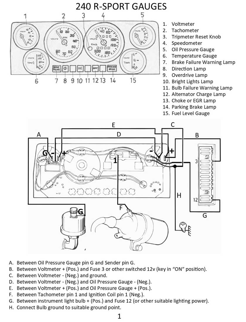
| Early 240 R Sport
Gauges |
|||
 <<< Here
's a diagram (PAGE 1) showing the pin-outs for the 240 R-Sport instrument cluster. This cluster uses a cable type speedometer.
<<< Here
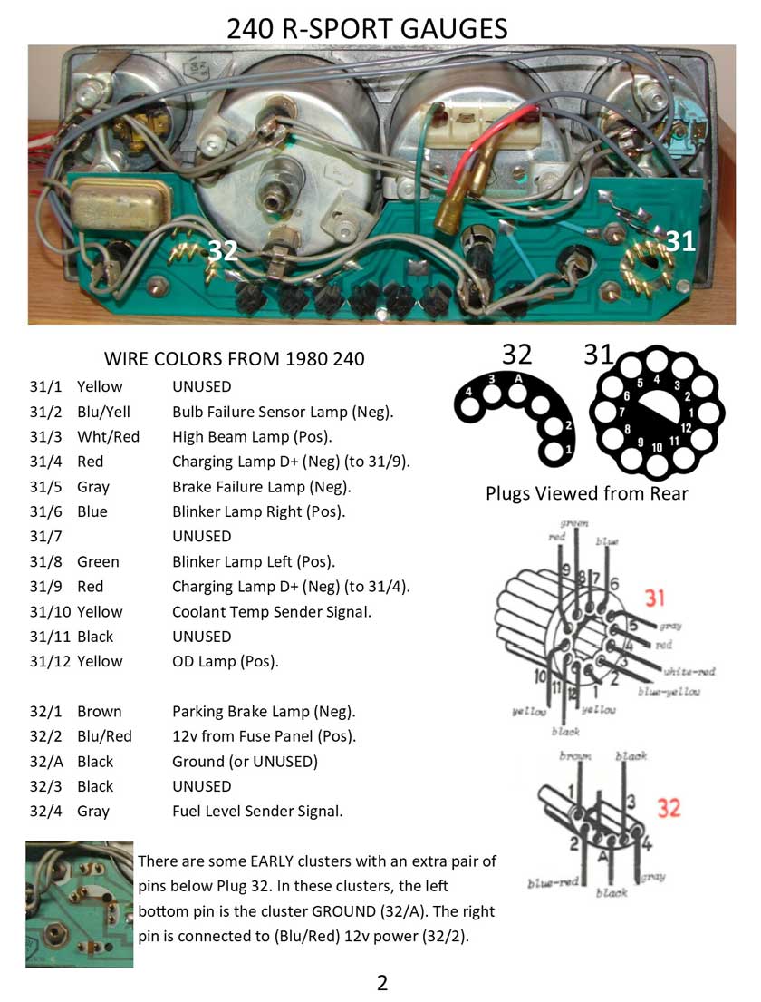
's a diagram (PAGE 1) showing the pin-outs for the 240 R-Sport instrument cluster. This cluster uses a cable type speedometer.Some of the connector pins in these images are noted with "Pos" or "Neg." These notations refer to the circuit polarity. Sometimes this can change from one year to another. For example, Pin 31/2 supplies a signal to the Brake Failure Lamp. That signal is a GROUND (Neg), which completes the circuit for that bulb, since it already has a power circuit supplied by the circuit board, which originates through Pin 32/2. Another example: Pin 31/12 supplies a signal to the OD Lamp. This signal is POSITIVE (12v), which completes the circuit for that bulb, since it already has a GROUND supplied by the circuit board, supplied through Pin 32/A. |
|||
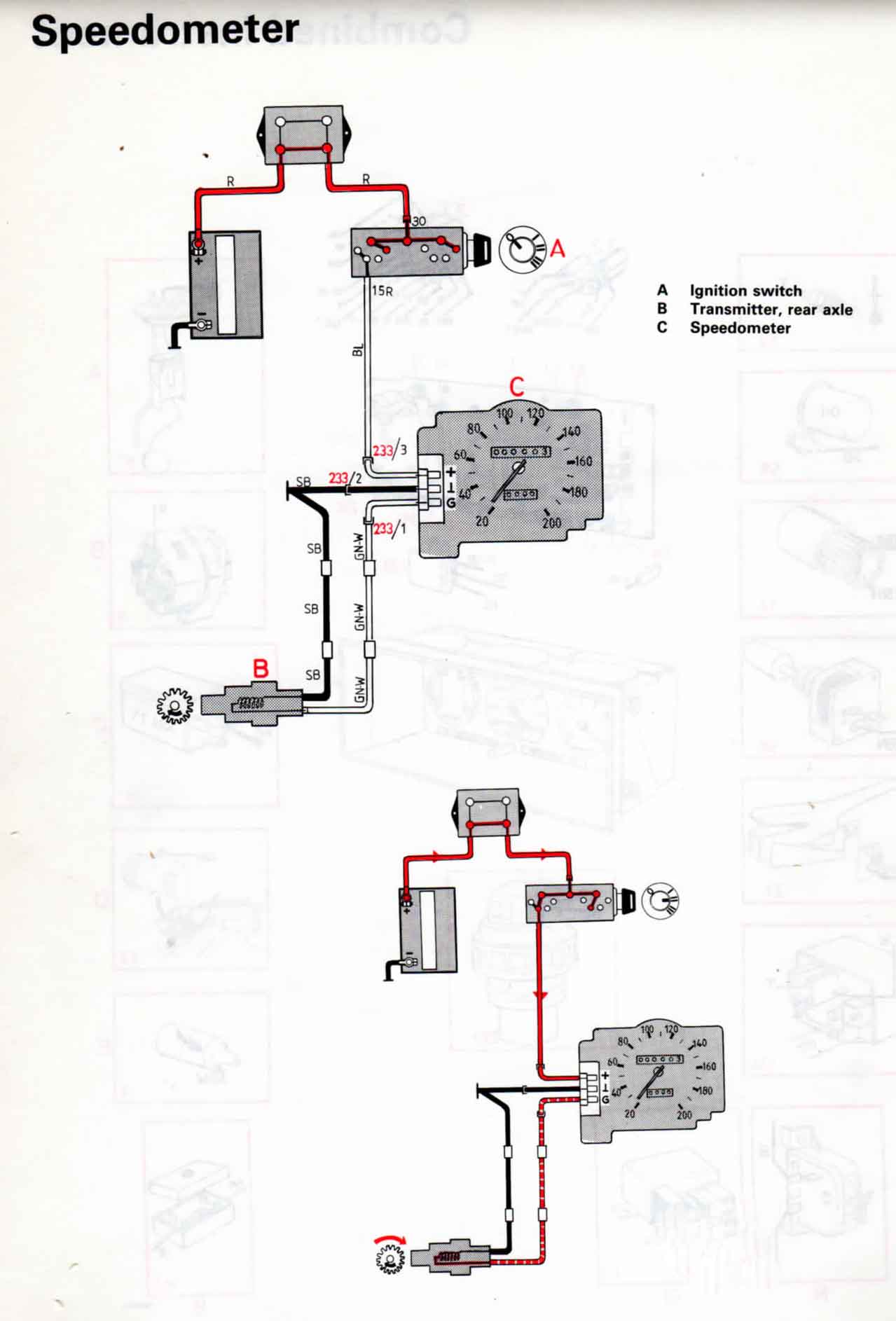
 <<< Here
's PAGE 2 for the R-Sport cluster diagram info. <<< Here
's PAGE 2 for the R-Sport cluster diagram info. |
|||
|
|
|||
|
1977-78 240 Gauge Assembly If you have noticed the HIGHER DETAIL in the below 1984 cluster info, I was able to do that because I have that cluster here. If anyone has a spare 1977-78 cluster that you are willing to lend me for a short time, I can improve this information. |
|||
 <<< Here
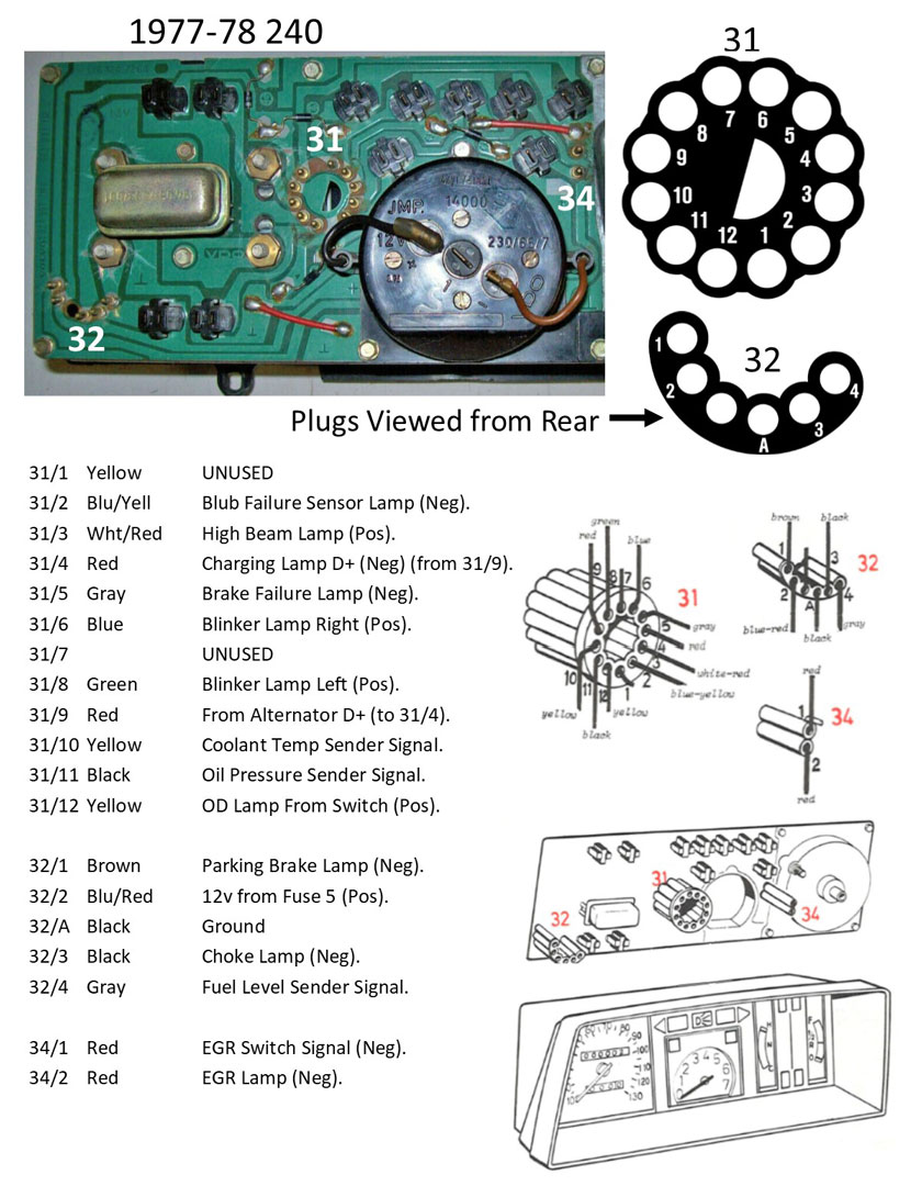
's a diagram showing the pin-outs for the 1977-78 240 instrument cluster. This cluster uses a cable type speedometer. <<< Here
's a diagram showing the pin-outs for the 1977-78 240 instrument cluster. This cluster uses a cable type speedometer.Some of the connector pins in these images are noted with "Pos" or "Neg." These notations refer to the circuit polarity. Sometimes this can change from one year to another. For example, Pin 31/2 supplies a signal to the Brake Failure Lamp. That signal is a GROUND (Neg), which completes the circuit for that bulb, since it already has a power circuit supplied by the circuit board, which originates through Pin 32/2. Another example: Pin 31/12 supplies a signal to the OD Lamp. This signal is POSITIVE (12v), which completes the circuit for that bulb, since it already has a GROUND supplied by the circuit board, supplied through Pin 32/A. NOTE: If you want to do similar lamp polarity tests to a different year cluster, first remove ALL lamps. Any remaining lamps still plugged in will skew your continuity tests. 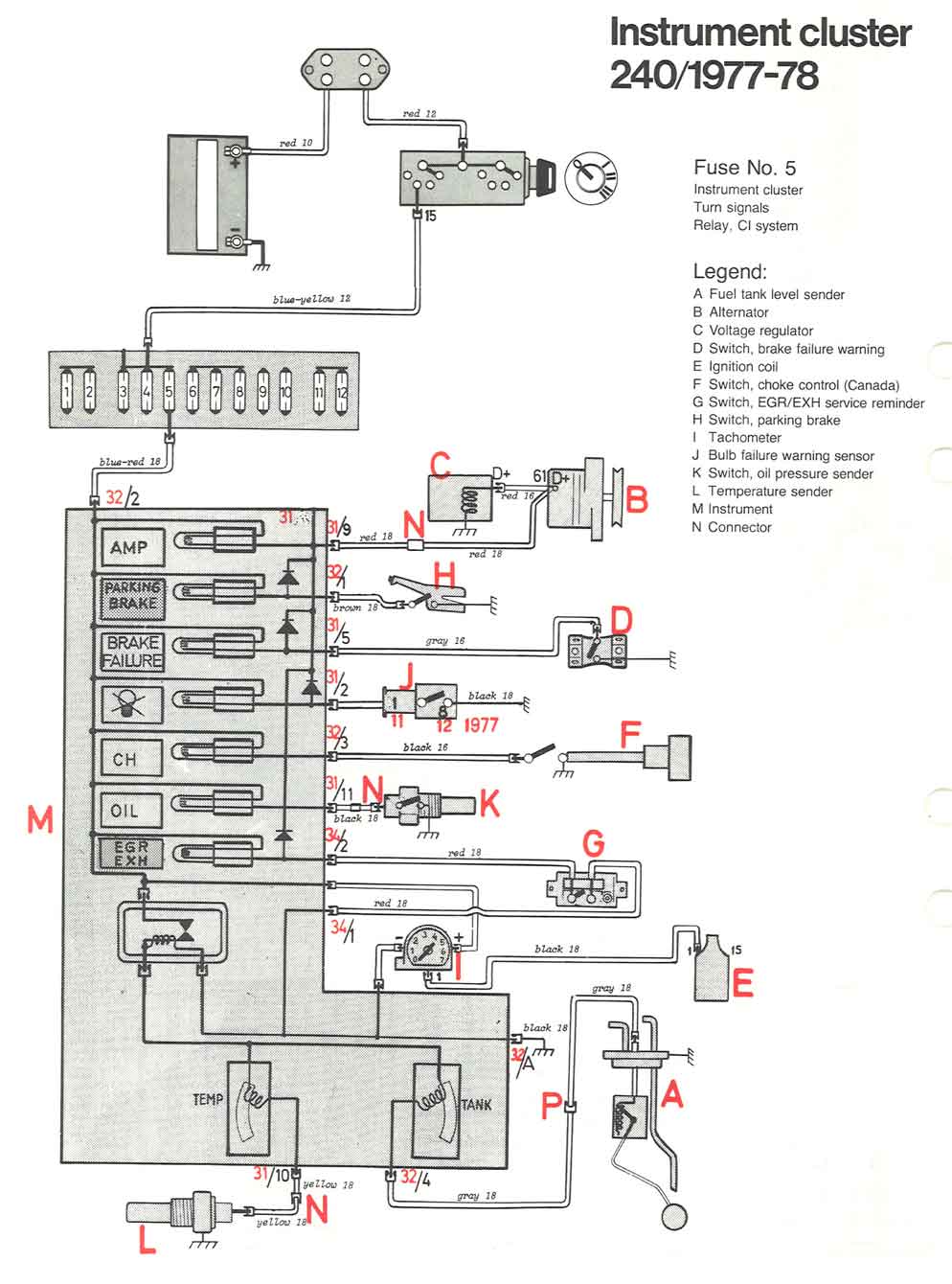 |
|||
|
|
|||
|
1980 240 Gauge Assembly If you have noticed the HIGHER DETAIL in the below 1984 cluster info, I was able to do that because I have that cluster here. If anyone has a spare 1980 cluster that you are willing to lend me for a short time, I can improve this information. |
|||
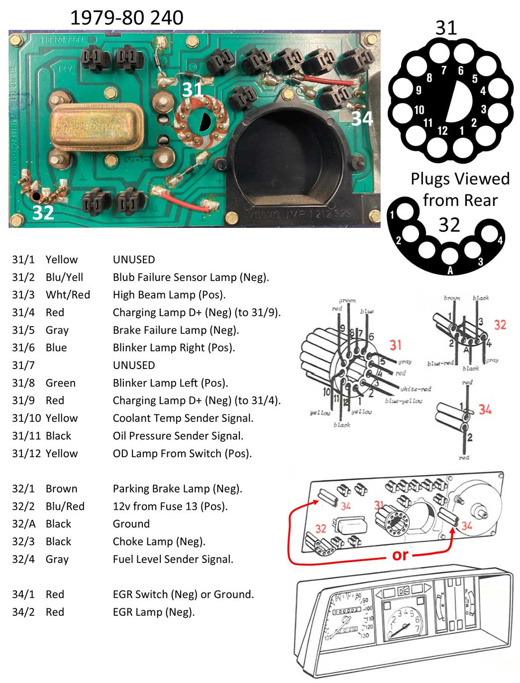 <<< Here
's a diagram showing the pin-outs for the 1980 240 instrument cluster. This cluster uses a cable type speedometer. <<< Here
's a diagram showing the pin-outs for the 1980 240 instrument cluster. This cluster uses a cable type speedometer.Some of the connector pins in these images are noted with "Pos" or "Neg." These notations refer to the circuit polarity. Sometimes this can change from one year to another. For example, Pin 31/2 supplies a signal to the Brake Failure Lamp. That signal is a GROUND (Neg), which completes the circuit for that bulb, since it already has a power circuit supplied by the circuit board, which originates through Pin 32/2. Another example: Pin 31/12 supplies a signal to the OD Lamp. This signal is POSITIVE (12v), which completes the circuit for that bulb, since it already has a GROUND supplied by the circuit board, supplied through Pin 32/A. NOTE: If you want to do similar lamp polarity tests to a different year cluster, first remove ALL lamps. Any remaining lamps still plugged in will skew your continuity tests. 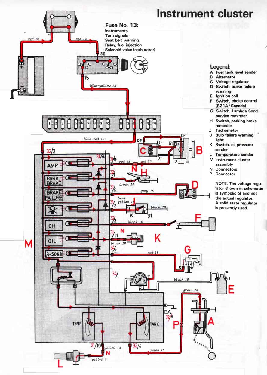
|
|||
|
|
|||
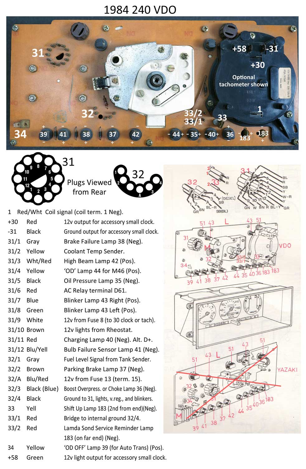
| 1984 240 Gauge Assembly
If you have noticed the HIGHER DETAIL in this 1984 cluster info below, I was able to do this because I have this cluster. If anyone has any spare clusters for other years and if you're willing to lend me one for a short time, I can improve the info for other clusters in this page. |
|||
 <<< Here
's a diagram showing the pin-outs for the 1984 240 instrument cluster. This cluster uses a cable type speedometer.
<<< Here
's a diagram showing the pin-outs for the 1984 240 instrument cluster. This cluster uses a cable type speedometer. I also have some more wiring circuit and circuit board info in the Voltage Regulator section further below in this page. Some of the connector pins in these images are noted with "Pos" or "Neg." These notations refer to the circuit polarity. Sometimes this can change from one year to another. Polarity example, Pin 31/1 supplies a signal to the Brake Failure Lamp. That signal is a GROUND (Neg), which completes the circuit for that bulb, since that bulb already has power supplied by the circuit board, which originates through Pin 32/A. Another example: Pin 31/4 supplies a signal to the OD Lamp (for M46). This signal is POSITIVE (12v), which completes the circuit for that bulb, since it already has a GROUND supplied by the circuit board, supplied through Pin 32/4. NOTE: If you want to do similar polarity tests to a different year cluster, first remove ALL lamps. Any remaining lamps still plugged in will skew your continuity tests. LAMPS: I have included detailed information about each lamp socket along the bottom, including the polarity of each lamp, which can be quite different from other nearby lamps. NOTE: If you want to do similar polarity tests a cluster you have, you must first remove ALL lamps. Any remaining lamps still plugged in will skew your continuity tests. Automatic or Manual Transmission: An automatic transmission car will not have a terminal in round plug 31 pin 4 (M46 overdrive lamp). So if you're converting a car from auto transmission to an M46 manual, you'll need to add a terminal to pin 31/4. Also you should remove the terminal plugged into Pin 34, which powers the "OD OFF" lamp used for the auto trans OD light. 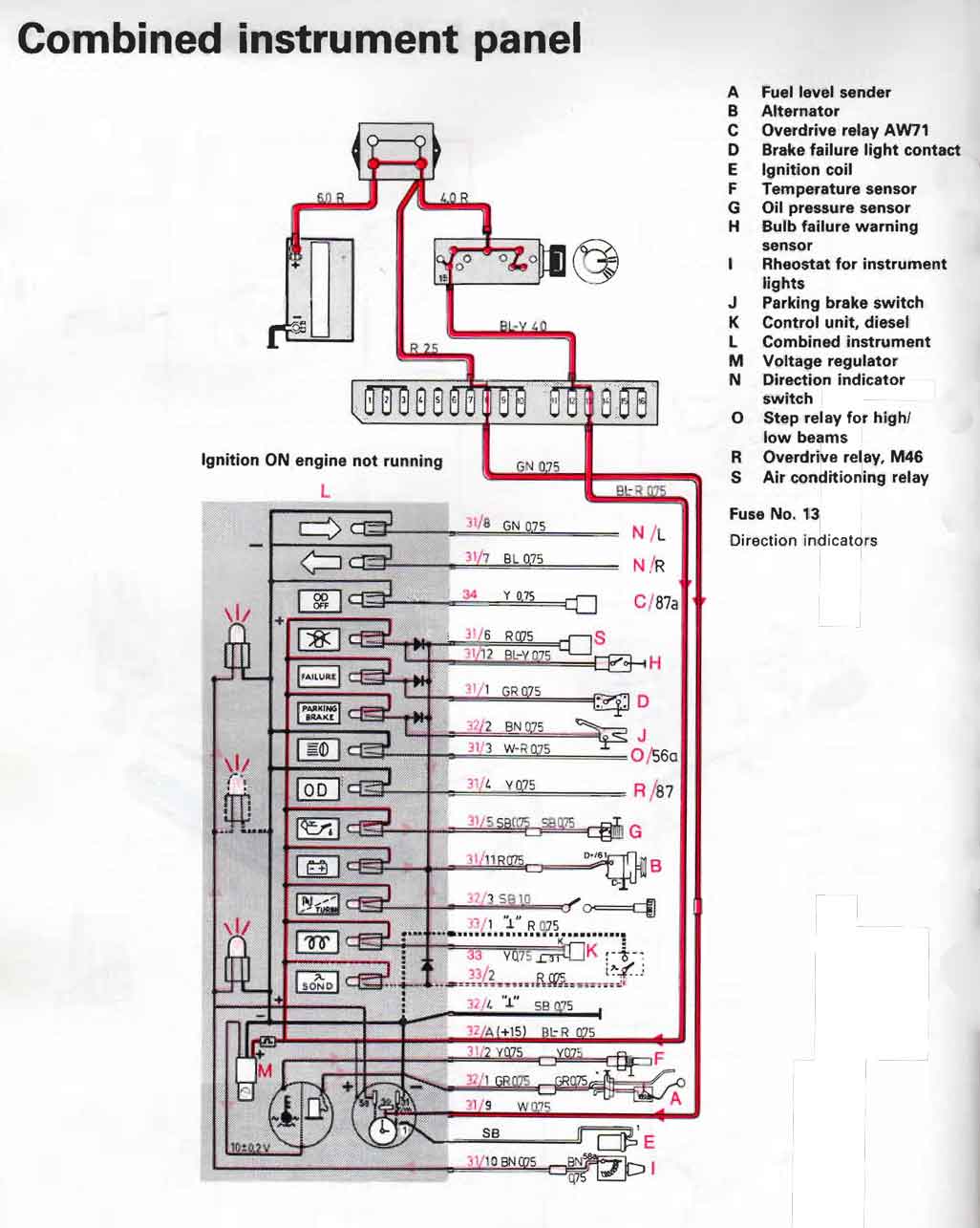 |
|||
|
|
|||
|
1986-87 240 Gauge Assembly If you have noticed the HIGHER DETAIL in the above 1984 cluster info, I was able to do that because I have that cluster here. If anyone has a spare 1986-87 cluster that you are willing to lend me for a short time, I can improve this information. |
|||
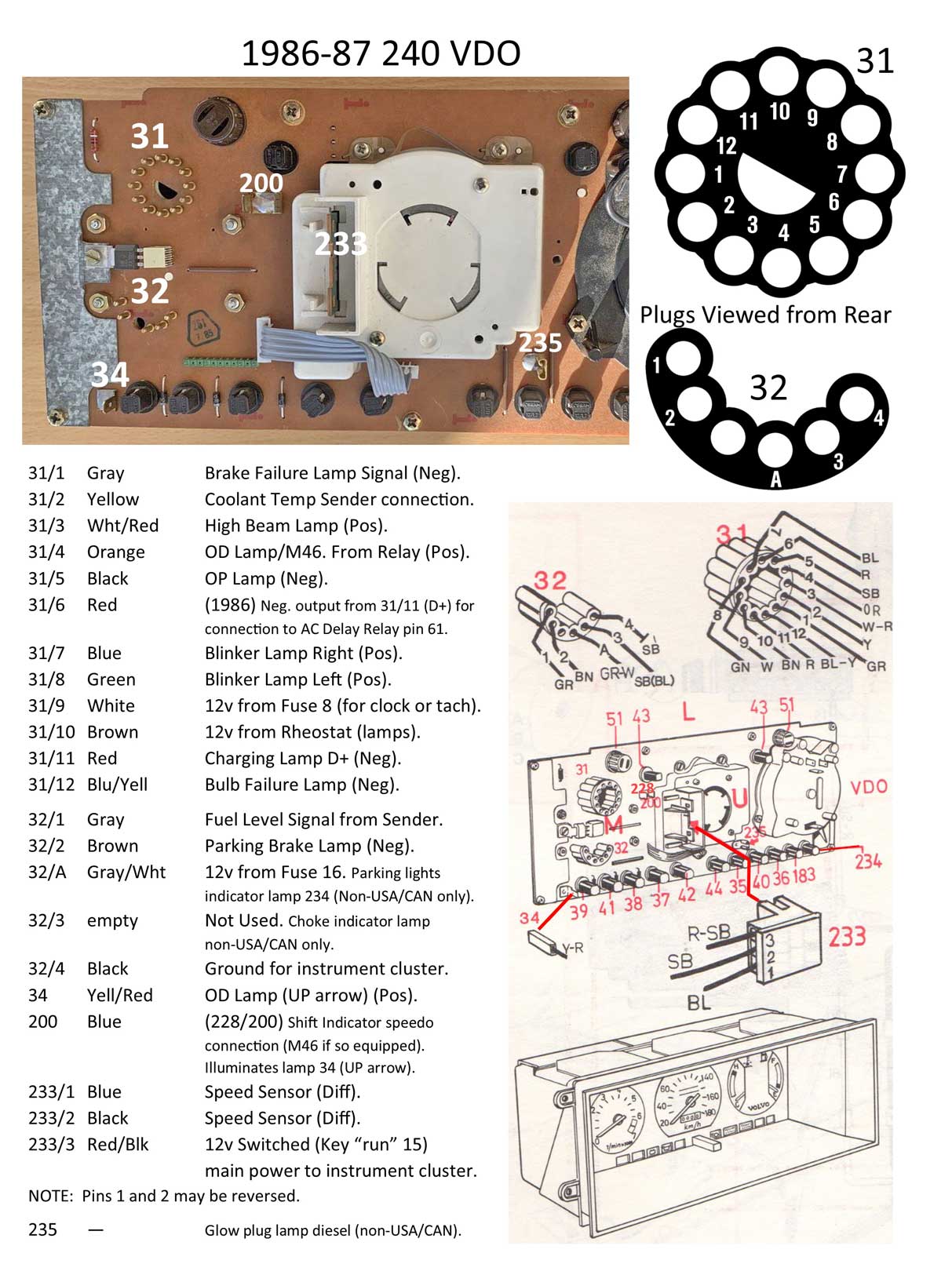 <<< Here
's a diagram showing the pin-outs for the 1986-87 240 instrument cluster. This cluster uses an
electronic speedometer, which was introduced in 1986.
<<< Here
's a diagram showing the pin-outs for the 1986-87 240 instrument cluster. This cluster uses an
electronic speedometer, which was introduced in 1986.POLARITY: Some of the connector pins in these images are noted with "Pos" or "Neg." These notations refer to the circuit polarity. Sometimes this can change in some places from one year to another. Polarity example: Pin 31/1 (round plug) supplies a signal to the Brake Failure Lamp. That signal is a GROUND (Neg), which completes the circuit for that bulb, since it already has a power circuit supplied by the circuit board, which originates through Pin 233/3. Another polarity example: Pin 31/4 supplies a signal to the OD Lamp (for M46). This signal is POSITIVE (12v), which completes the circuit for that bulb, since it already has a GROUND supplied by the circuit board, supplied through Pin 32/4. NOTE: If you want to do similar polarity tests, you must first remove ALL lamps. Any remaining lamps still plugged in will skew your continuity tests. PIN 200 NOTES: This pin (also called 228/200) is there to offer a vehicle speed signal (VSS). It's used for an optional Gear Shift Indicator Lamp in manual transmission car or for connection to an optional Cruise Control ECU. More info is discussed in my LH 2.4 Conversion Info HERE. Automatic Transmissions: An automatic transmission car will NOT have a terminal in the round plug Pin 31/4 (M46 overdrive lamp). So if you're converting a car from auto transmission to an M46 manual, you'll need to add a 2 mm female terminal to pin 31/4. Also be sure to remove the terminal from Pin 34, which powers the "OD OFF" (UP arrow) lamp that was used for the automatic transmission OD/4th gear lamp. Manual Transmissions: The M46 was used through 1986 and then discontinued for the 240. Beginning in 1987 Volvo began using the M47 transmission for manual 240s. In 1989, the traditional OD lamp to the left of the reset button became a "5" lamp, at least in clusters with the K10042 speedometer. Temperature Stabilizer: A temperature stabilizer board (temp faker) was introduced for the 1986 and later models. The purpose of this board was to stabilize temperature gauge needle fluctuations at extreme engine temperatures so drivers would stopped being alarmed and complaining to Volvo dealers. More about this feature is found here. 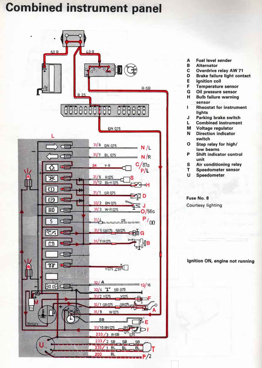
|
|||
|
|
|||
|
1990 240 Gauge Assembly If you have noticed the HIGHER DETAIL in the above 1984 cluster info, I was able to do that because I have that cluster here. If anyone has a spare 1990 cluster that you are willing to lend me for a short time, I can improve this information. |
|||
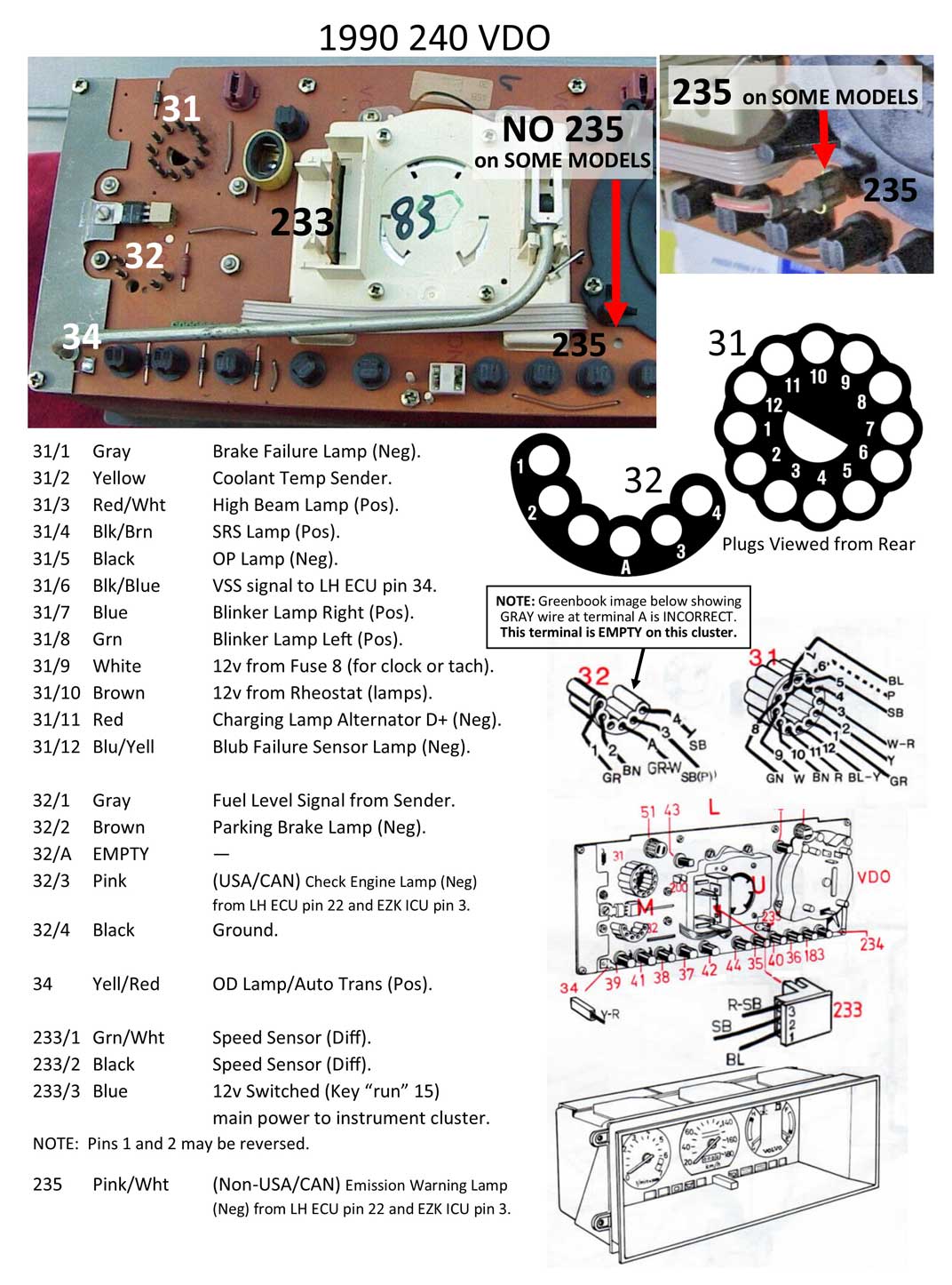 <<< Here
's a diagram showing the pin-outs for the 1990 240 instrument cluster. This cluster uses an electronic speedometer and is for an ABS or non-ABS car. <<< Here
's a diagram showing the pin-outs for the 1990 240 instrument cluster. This cluster uses an electronic speedometer and is for an ABS or non-ABS car.In 1989 Volvo improved the instrument lighting with the introduction of 3 watt halogen bulbs (TP31291 1989 240 New Car Features, pg 2). Some of the connector pins in these images are noted with "Pos" or "Neg." These notations refer to the circuit polarity. Sometimes this can change from one year to another. Polarity example: Pin 31/1 supplies a signal to the Brake Failure Lamp. That signal is a GROUND (Neg), which completes the circuit for that bulb, since it already has a power circuit supplied by the circuit board, which originates through Pin 233/3. Another example: Pin 31/4 supplies a signal to the SRS lamp. This signal is POSITIVE (12v). This positive signal will complete the circuit for the SRS bulb, since it already has a GROUND connected through the circuit board. NOTE: If you want to do similar polarity tests for lamps in your cluster, first remove ALL lamps. Any remaining lamps still plugged in will skew your continuity tests. Note regarding Pin 235: Some 1990 clusters were equipped with pin 235 and some were not. Both variants were found in 1990 cars imported to USA and Canada.. According to the 1990 Greenbook, 240 New Car Features TP 31528, using pin 235 Check Engine Light (CEL) was restricted to NON-USA/CANADIAN models. For USA and Canadian cars, the CEL was activated through pin 32/3 (in the half moon plug). 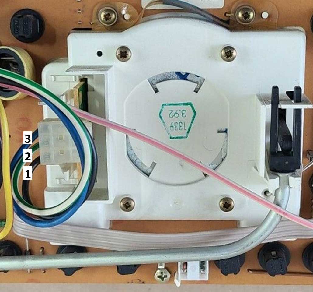 Note regarding changes in Speedometer 3-pole connector circuits (ABS versus NON-ABS cars):
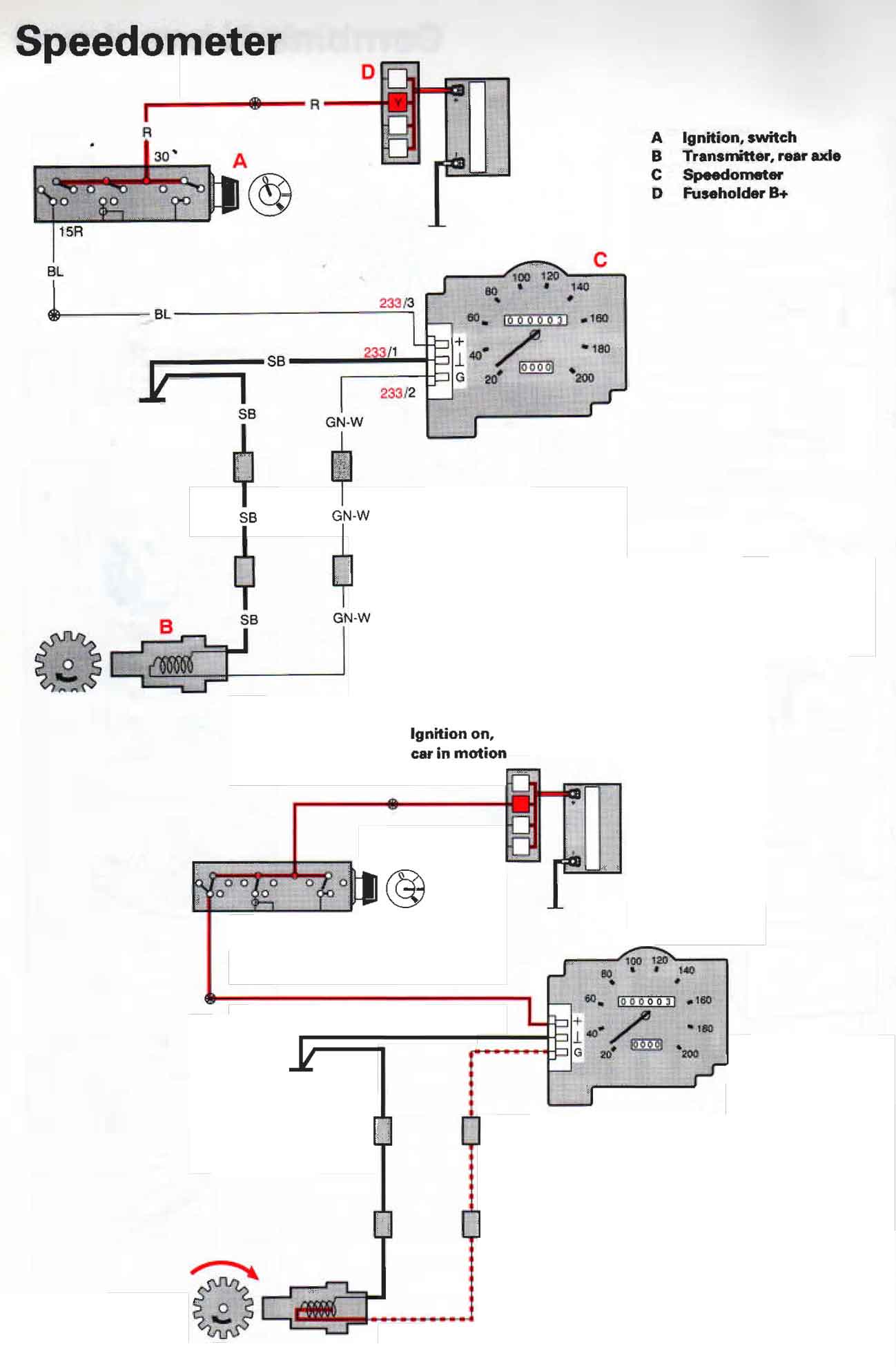
Keep in mind that the 3-pole speedometer plug (233) will
always have Pin 1 and the bottom and Pin 3 at the top (as seen in this
photo). The wire colors can change sometimes in different years. Pin 3 at the top should always be
the POWER wire. Pins 1 and 2 should always go to the Vehicle Speed Sensor (VSS) in the
differential.
You might find the
wire colors for Pins 1 and 2 (sensor) are swapped sometimes. I have been told this has something to do with if you have an ABS car or a non-ABS car.
ABS typically became an option in the U.S. in 1991 and standard in 1992-93. Note regarding changes in Speedometer 3-pole connector circuits (ABS versus NON-ABS cars):
Keep in mind that the 3-pole speedometer plug (233) will
always have Pin 1 and the bottom and Pin 3 at the top (as seen in this
photo). The wire colors can change sometimes in different years. Pin 3 at the top should always be
the POWER wire. Pins 1 and 2 should always go to the Vehicle Speed Sensor (VSS) in the
differential.
You might find the
wire colors for Pins 1 and 2 (sensor) are swapped sometimes. I have been told this has something to do with if you have an ABS car or a non-ABS car.
ABS typically became an option in the U.S. in 1991 and standard in 1992-93. Temperature Stabilizer: A temperature stabilizer board (temp faker) was introduced for the 1986 and later models. The purpose of this board was to stabilize temperature gauge needle fluctuations at extreme engine temperatures so drivers would stopped being alarmed and complaining to Volvo dealers. More about this feature is found here. NOTE regarding using an M46: The M46 was used in 240s through 1986 and then discontinued for the 1987 240. Beginning in 1987 Volvo began using the M47 transmission for manual 240s. The M46 was still used in 700 turbo models and 16 valve models through 1990, because it was stronger than the M47. The M46 then became obsolete in all cars by 1991. In 1989, the traditional OD lamp to the left of the reset button became a "5" lamp, at least in clusters with the K10042 speedometer. The 1990 and later cluster will probably not have an M46 OD lamp at all, since that lamp position was replaced by an SRS lamp. If an M46 OD light is needed on the 1990 cluster, you may try reworking the OD arrow lamp (normally for auto trans) in this cluster. Otherwise some custom work may need to be done to add a traditional OD lamp. 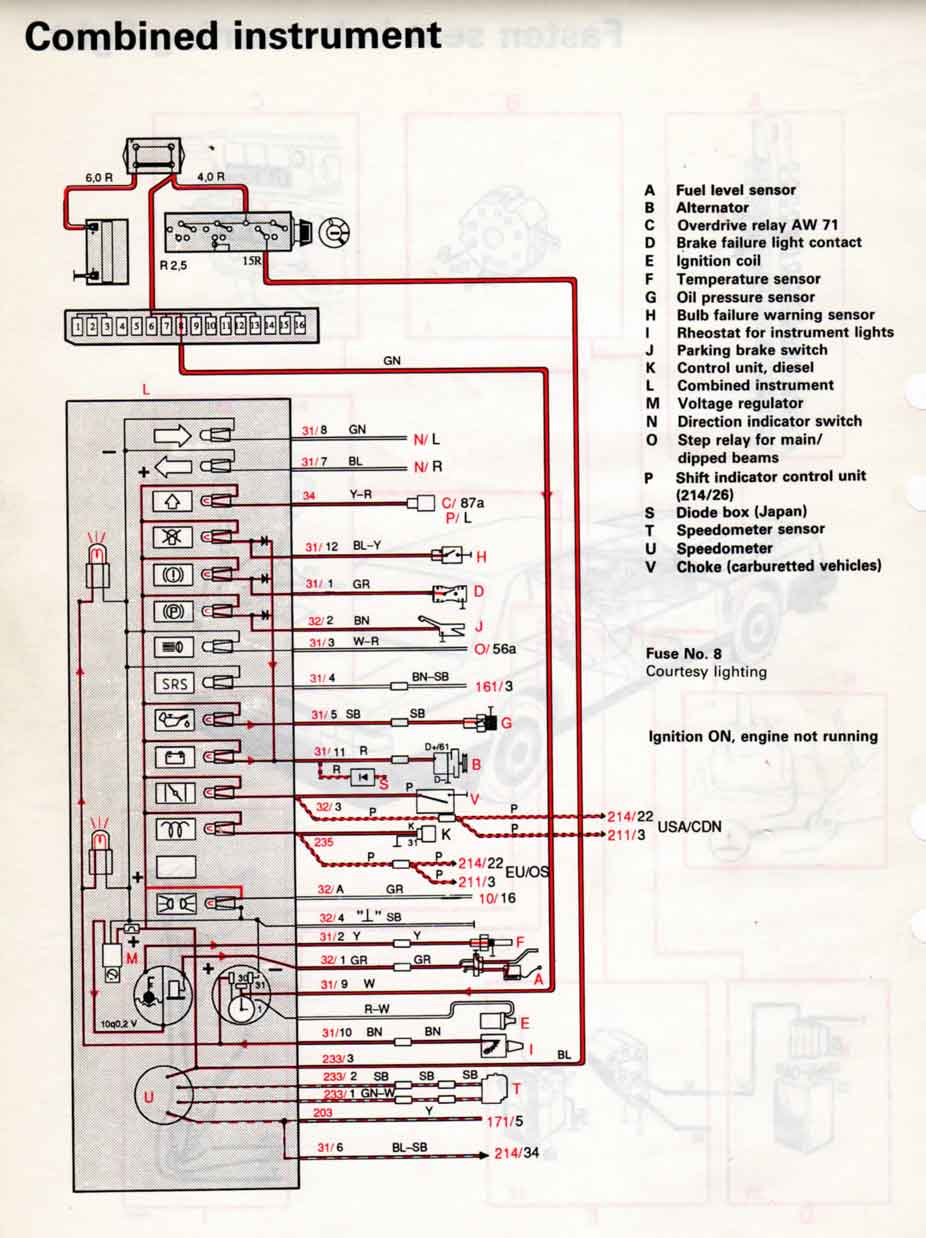
 |
|||
|
|
|||
| 1993 240 Gauge Assembly If you have noticed the HIGHER DETAIL in the above 1984 cluster info, I was able to do that because I have that cluster here. If anyone has a spare 1993 cluster that you are willing to lend me for a short time, I can improve this information. |
|||
 <<< Here's a diagram showing the pin-outs for the 1993 240 instrument cluster.
This cluster uses an electronic speedometer and is for an ABS car.
<<< Here's a diagram showing the pin-outs for the 1993 240 instrument cluster.
This cluster uses an electronic speedometer and is for an ABS car.Some of the connector pins in these images are noted with "Pos" or "Neg." These notations refer to the circuit polarity. Sometimes this can change from one year to another. Polarity example, Pin 31/1 supplies a signal to the Brake Fluid Level Lamp. That signal is a GROUND (Neg), which completes the circuit for that bulb, since it already has a power circuit supplied by the circuit board, which originates through Pin 233/3. NOTE: If you want to do similar polarity tests for lamps, first remove ALL lamps. Any remaining lamps still plugged in will skew your continuity tests. Note regarding changes in Speedometer 3-pole connector circuits (ABS versus NON-ABS cars):
Keep in mind that the 3-pole speedometer plug (233) pin numbers will
always have Pin 1 at the bottom and Pin 3 at the top (as seen in this
photo). The wire colors can change sometimes in different years. Pin 3 at the top should always be
the POWER wire. Pins 1 and 2 should always go to the sensor in the
differential. You
might find the wire colors for Pins 1 and 2 (sensor) are swapped in
some cars. I have been told this has something to do with if you have an ABS car or a non-ABS car.
ABS typically became an option in the U.S. in 1991 and standard in 1992-93. Temperature Stabilizer: A temperature stabilizer board (temp faker) was introduced for the 1986 and later models. The purpose of this board was to stabilize temperature gauge needle fluctuations at extreme engine temperatures so drivers would stopped being alarmed and complaining to Volvo dealers. More about this feature is found here. NOTE regarding using an M46: This later cluster does not have an M46 OD lamp, since that lamp position was replaced by an SRS lamp beginning about 1990. The M46 was discontinued in the 240 after 1986. All manual transmission 240s began getting the M47 in 1987. The M46 was still used in 700 turbo models and 16 valve models through 1990, because it was stronger than the M47. The M46 then became obsolete in all cars by 1991. If an M46 OD light is needed on this 1990 cluster, you may try reworking the OD arrow lamp (auto trans) in this cluster. Otherwise some custom work may need to be done to add a traditional OD lamp. In 1989, the traditional OD lamp to the left of the reset button became a "5" lamp, at least in clusters with the K10042 speedometer. Note about Cruise Control: The speedometer VSS output circuit at 31/6 (which goes to LH ECU pin 34) also goes to Cruise Control ECU pin 5 (normally a yellow wire). MODIFIED LATER CLUSTERS: Here is some info submitted by a customer who modified his late 240 cluster>>> GaugesStyle5.html#clustermod 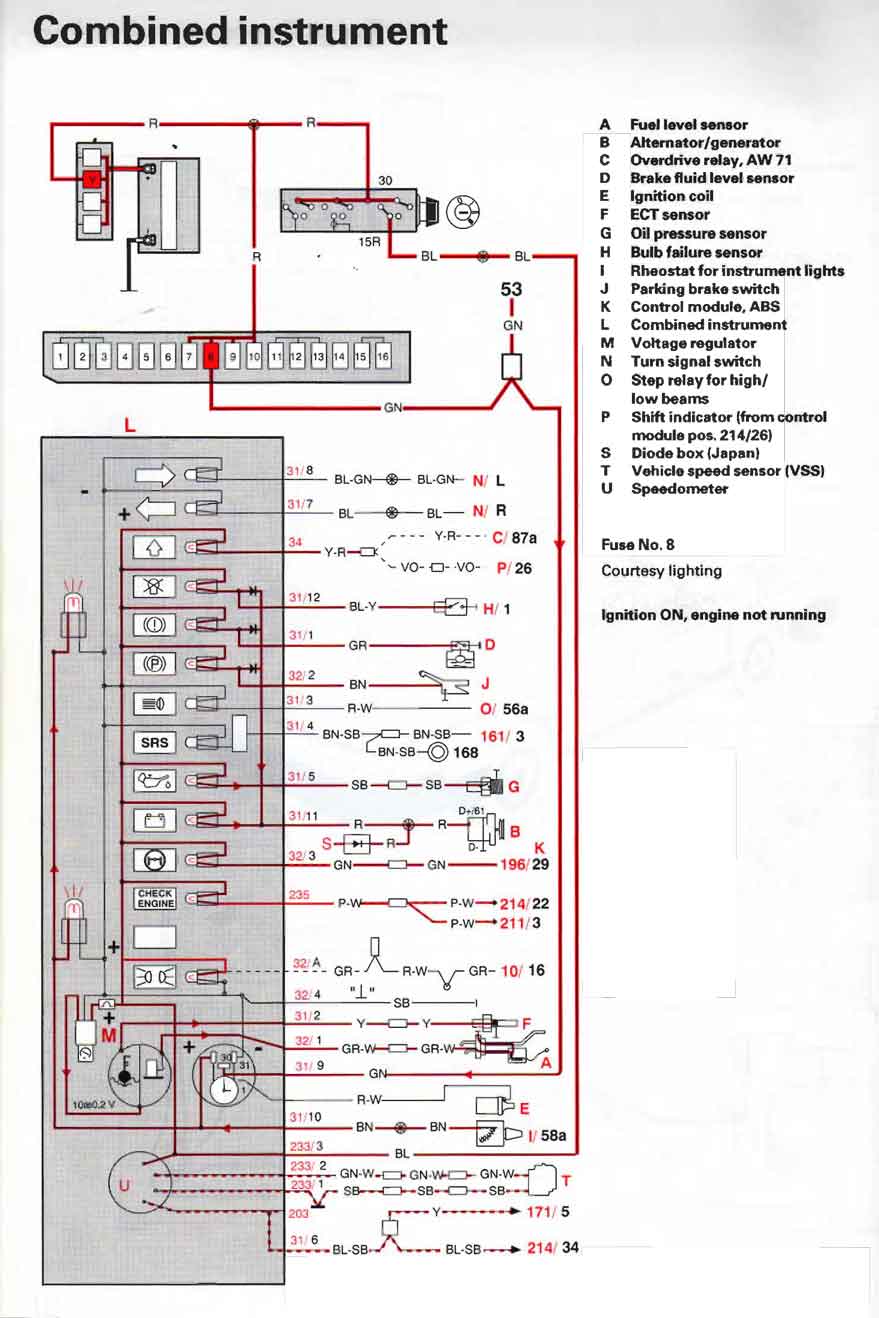
 |
|||
|
240 Instrument Cluster Voltage Regulator (VR) |
|||
A
240 gauge cluster has a voltage regulator (VR) on the back. It's not for
regulating all power coming into the cluster. It only regulates the power branching off to the TEMP gauge and FUEL gauge. It's
there to provide a steady 10 volts to those gauges only, so those gauges will be consistent
even when your battery voltage fluctuates up or down.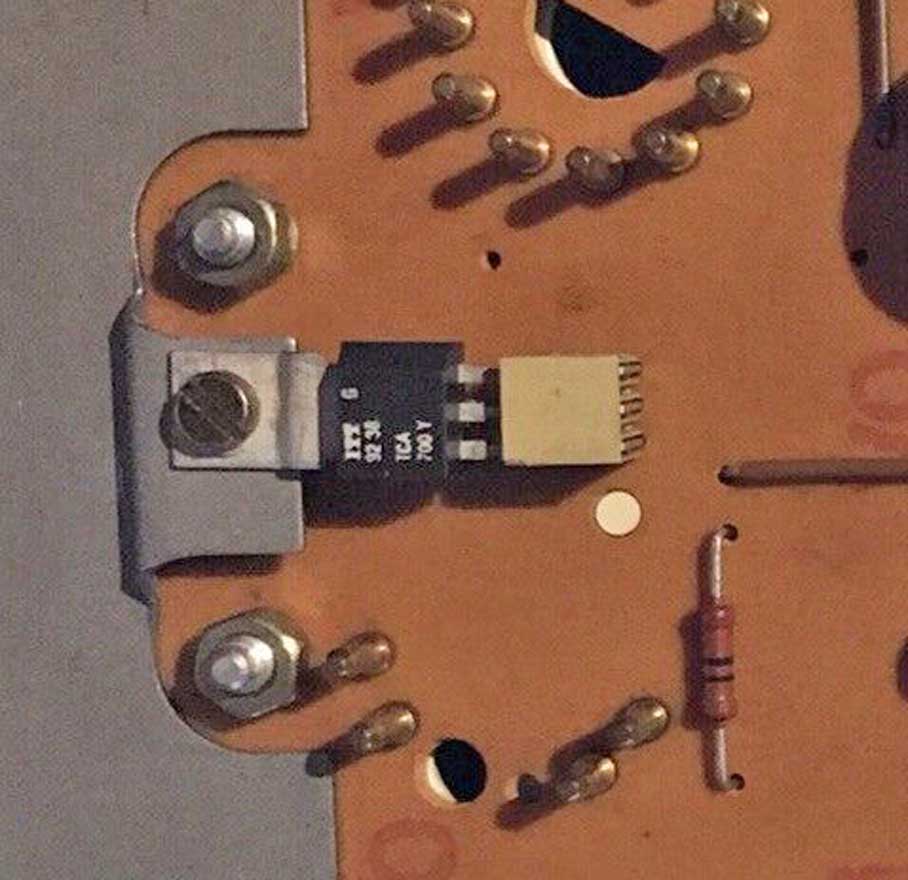 This VR is known as a linear voltage regulator. It's found here (above) on the rear of a 1986 or LATER 240 instrument cluster (earlier clusters are pictured below). The VR original Volvo PN is 1259755 (original ones now are difficult to find). VR FUNCTION It's function is to stabilize voltage to the dash temperature and fuel gauges by providing a consistent voltage for consistent gauge readings. If voltage to these gauges is not regulated, then if voltage from the charging system were to fluctuate, these gauges would change how the needles show the temp or fuel levels. The original VR that VDO used when making these clusters is designated as an ITT TCA700Y, which is hard to find now. A suitable or reasonable replacement is believed to be the L7810 10v voltage regulator shown below. The "L" stands for LINEAR. This is a linear voltage regulator. Some photos here were taken from page 1 of this discussion thread: turbobricks.com/greek-hopefully-fast-240-brick.310632/ While measuring his original VR output, the writer of this post discovered it was malfunctioning. It stabilized the voltage to 10v ONLY when power input was below 11.9v. If battery input became higher than 11.9v the VR output began to increase above the required 10 volts (i.e.: increasing input to 13.5v-14.5v resulted in 11v to 12v output). To correct this, he replaced it with a new L7810 voltage regulator. Please note that the new L7810 should be FLIPPED OVER and mounted upside down on this 240 cluster, since its outer pins are REVERSED compared to the original ITT TCA700Y regulator. The only other modification needed may be bending the L7810 pins outward a bit to help it comfortably fit the female receptacles. Also maybe a little trimming or cutting of the metal mounting bracket might be needed. The NEW L7810 regulator looks like this below when mounted on a 1986-93 gauge cluster. 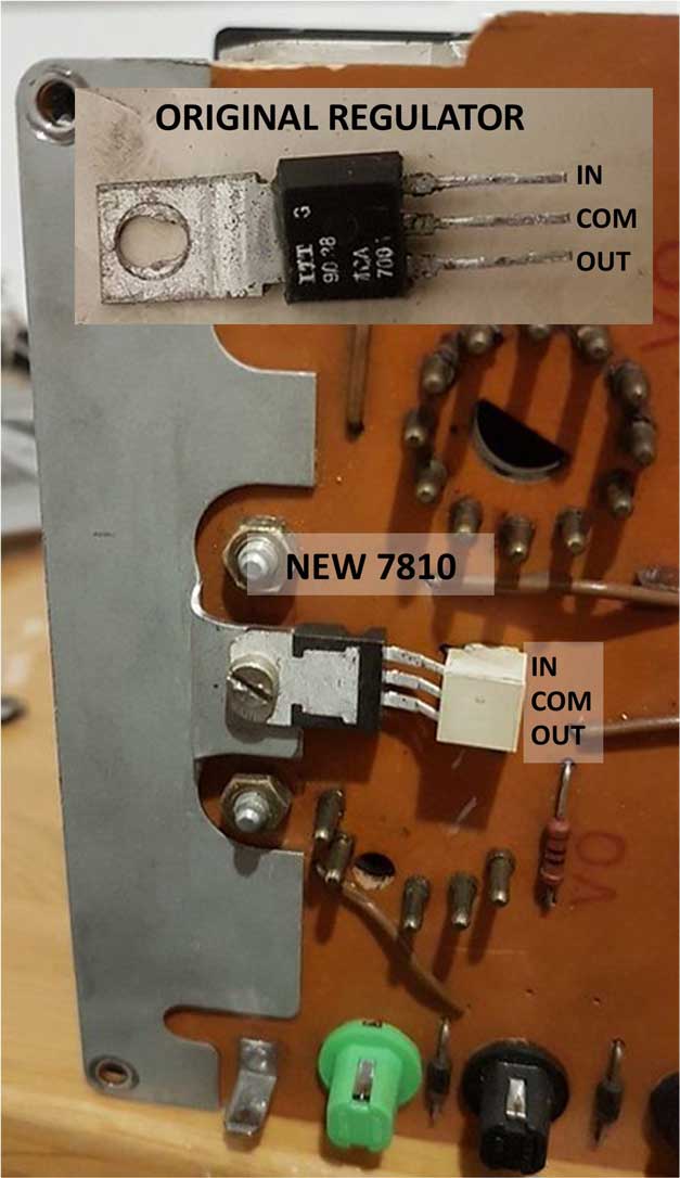
1974-80 240 The ORIGINAL early voltage regulator looks like this BELOW on a 1980 or older 240 cluster. 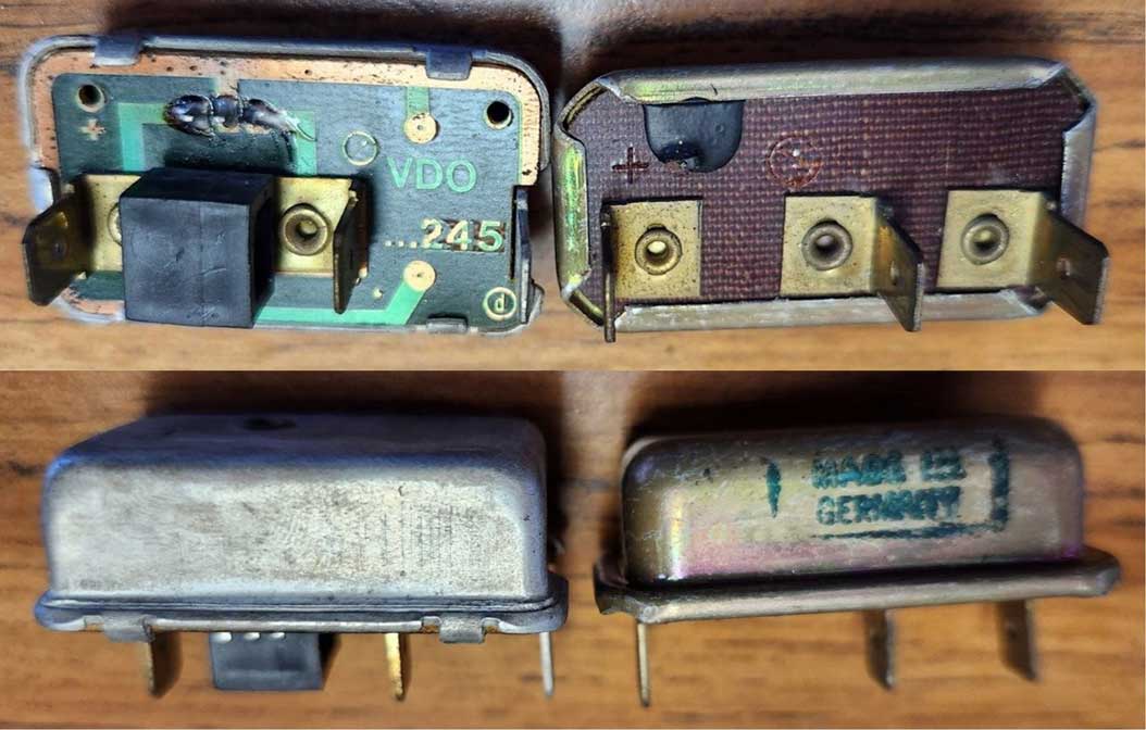 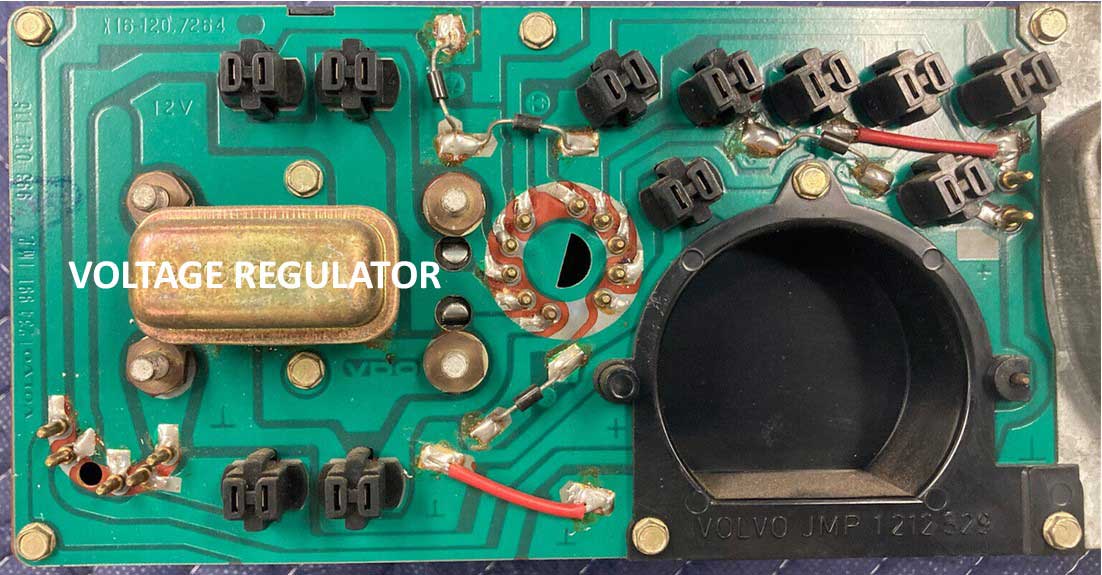 The function is the same as a later cluster regulator, so it is certainly possible to replace it with the L7810 10 volt regulator. The old regulator simply pulls off of the female terminals. Here's a diagram BELOW I made. Some simple .250 inch (6.3 mm) quick-connect MALE terminals can be used to plug into the three instrument cluster inputs. 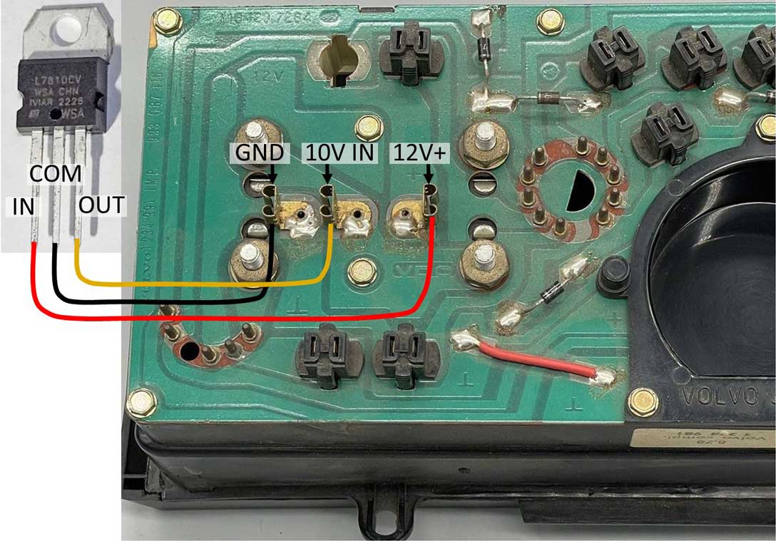 Mike P. in Canada sent me a photo of his early gauge cluster when he installed a new L7810 CV 10V regulator in place of the old one. It's found further below: CLICK HERE. 1981-85 240 The ORIGINAL voltage regulator looks like this BELOW on a 1981-85 instrument cluster. 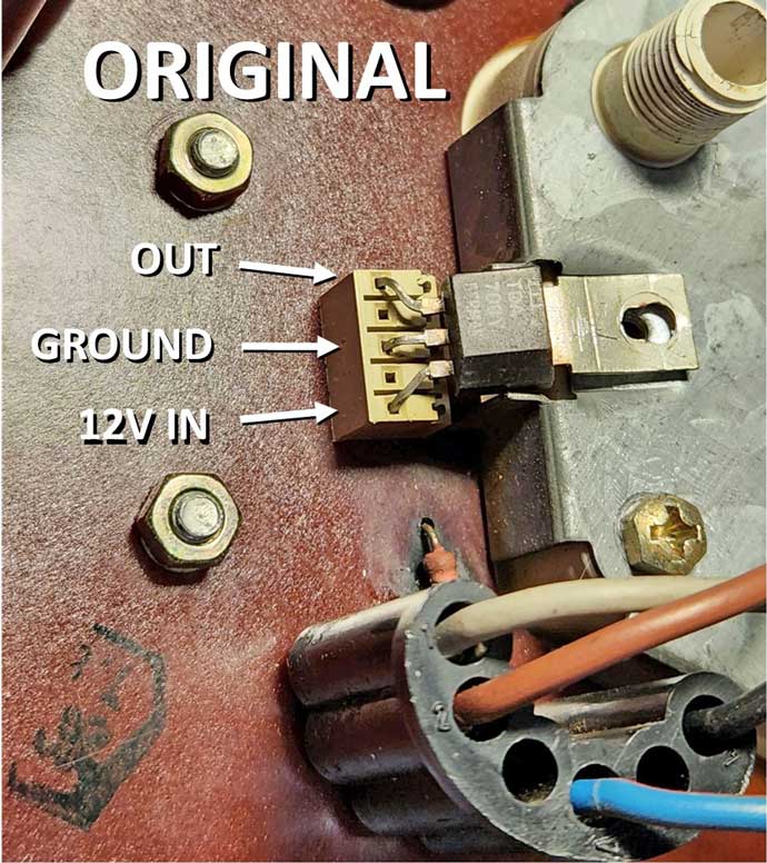 The pins will need to be spread outward a little on the new L7810 VR. This is easy with some needle nose pliers. 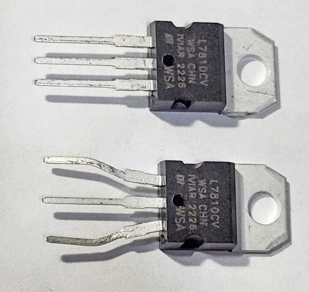 Flipping the new VR over is also required on this cluster when replacing with an L7810 regulator. With the pins pointing down, insert the pins first into the sockets, then fold the VR legs over to allow the mounting bracket screw hole to line up. In this installation above I trimmed a bit off the bracket with wire clippers. 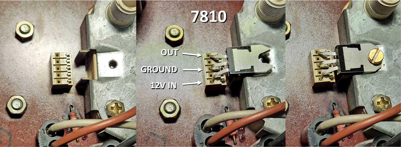 If you're curious how the VR is wired through this 1984 circuit board to the Temp and Fuel gauges, some images below will help. 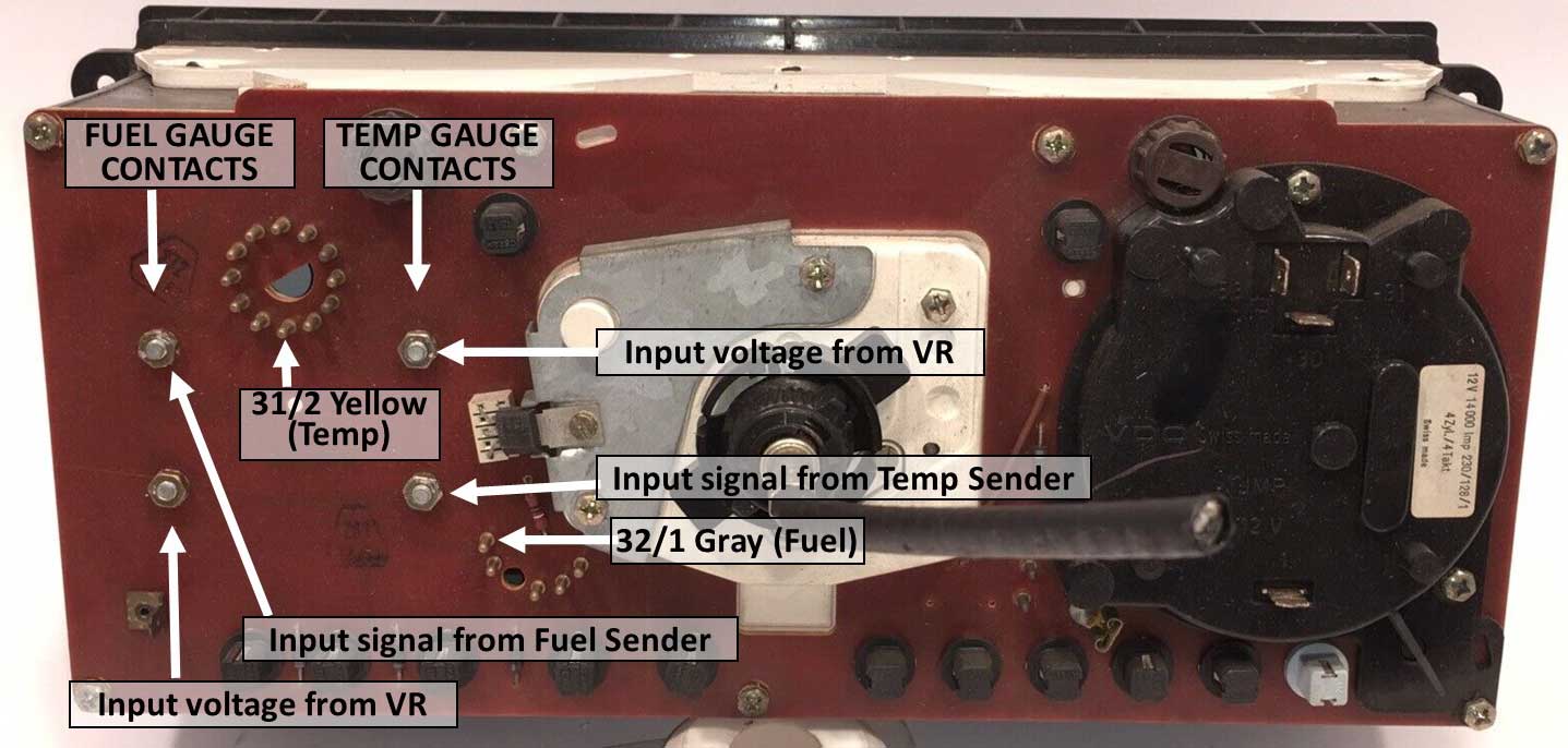 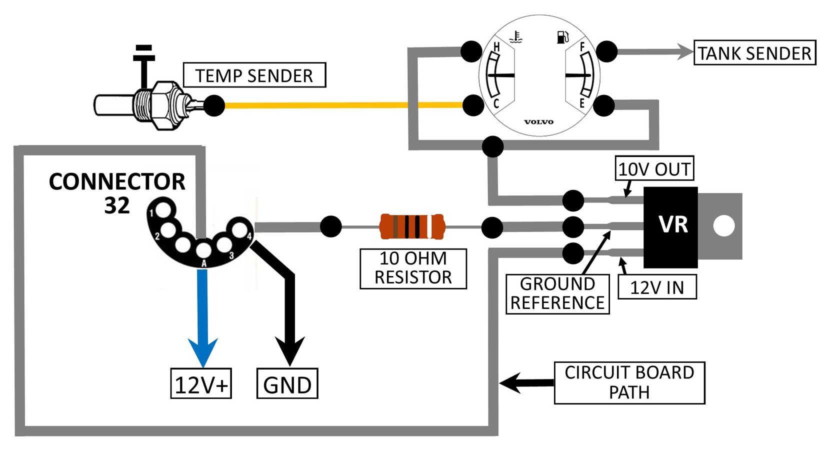 The VR is supposed to take the battery system voltage (which may be around 12 to 14 volts) and change it to a stable or constant 10 volts. The battery voltage comes into the instrument cluster through Conn 32, Pin A (half round connector). Battery voltage then goes through the circuit board to the VR 12V INPUT. Voltage goes through the VR and then 10 volts exits the VR and goes to the Temp and Fuel gauges. The FOUR HEX NUTS that you see behind the temp and fuel gauges are not only there to keep them mounted. Each nut also connects the gauges electronically to the circuit board. If needed, those nuts can be touched with a probe when testing gauges without a need to open the cluster. NOTES ON THE L78XX SERIES VOLTAGE REGULATOR I have read about lots of people reporting good results when using a L78XX VR on a 240 cluster, HOWEVER, when I showed the ABOVE circuit board diagram to someone I know with an expertise in linear voltage regulators, he told me he couldn't understand how this combination using an L78XX VR provides a long term durable or stable 10 volts. He suggested that it was possible the original ITT VR was a better product than the current L78XX series VRs. Maybe the original just worked better than what we now expect from an L78XX series VR. He was suggesting that using an L78XX as a replacement may be inadequate in the long run, since it was his opinion the L78XX VRs are notorious for becoming unstable unless some CAPACITANCE is added during installation. I did some internet research on this comment. That revealed to me it's a good established practice to use capacitors with any L78XX series linear regulator. At least one capacitor in-line on the VR output is recommended. And it's quite common to use TWO capacitors as shown below; One on the input and one on the output. I found that most PUBLISHED DATASHEETS for L78XX VRs recommend a 0.33uF capacitor from input to ground and a 0.1uF capacitor from output to ground. If polarized capacitors are used, be sure to recognize the polarity and connect the PLUS(+) side of each capacitor toward power and away from ground. If smaller non-polar capacitors are used, then polarity will not matter. 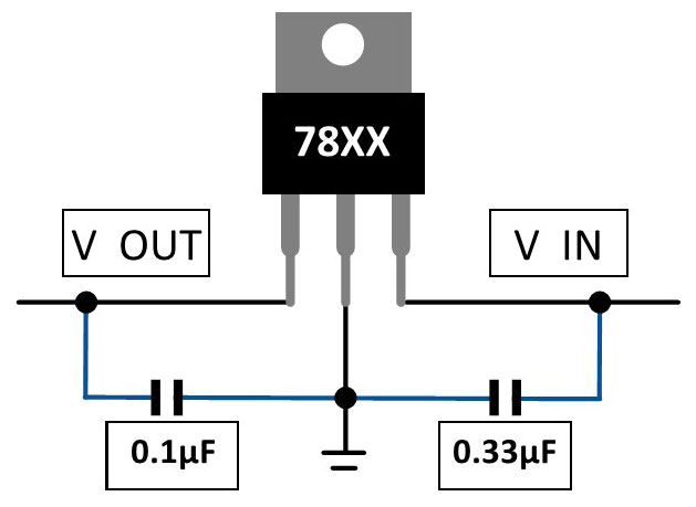 Mike P. from Canada then sent me this photo BELOW of his new L7810 CV 10V regulator in place of the old one. This is on an early 240 cluster. Look closely and you can see he also installed two ceramic (non-polar) capacitors as outlined above to help stabilize the regulator. He reported great results. 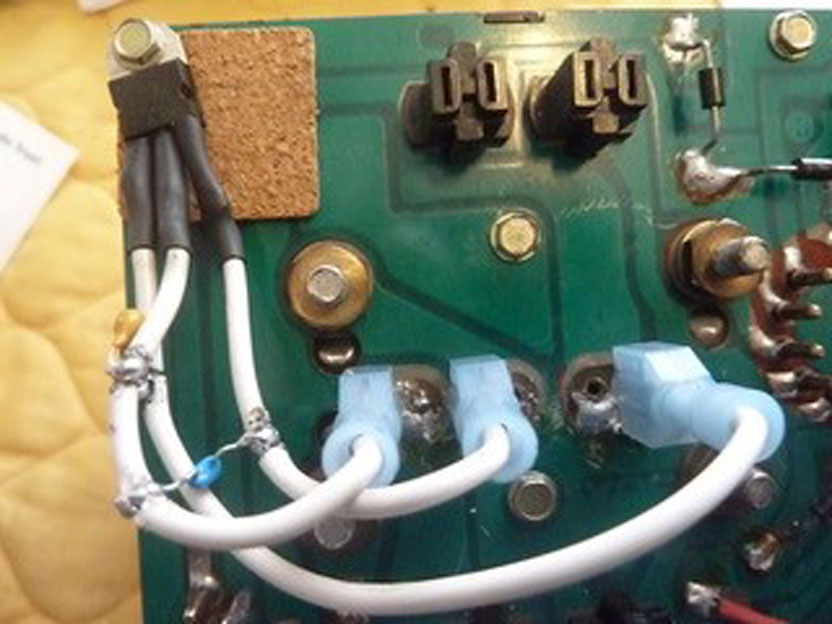 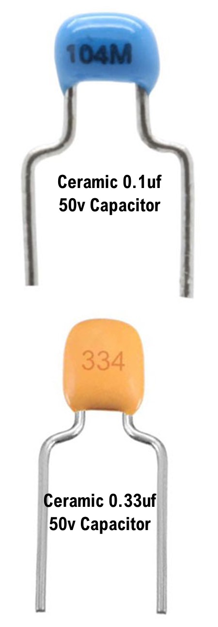 More DETAILED info about the pin-outs of these round and half-round pin connectors can be found in the 240 Cluster Diagrams section near the top of this page. 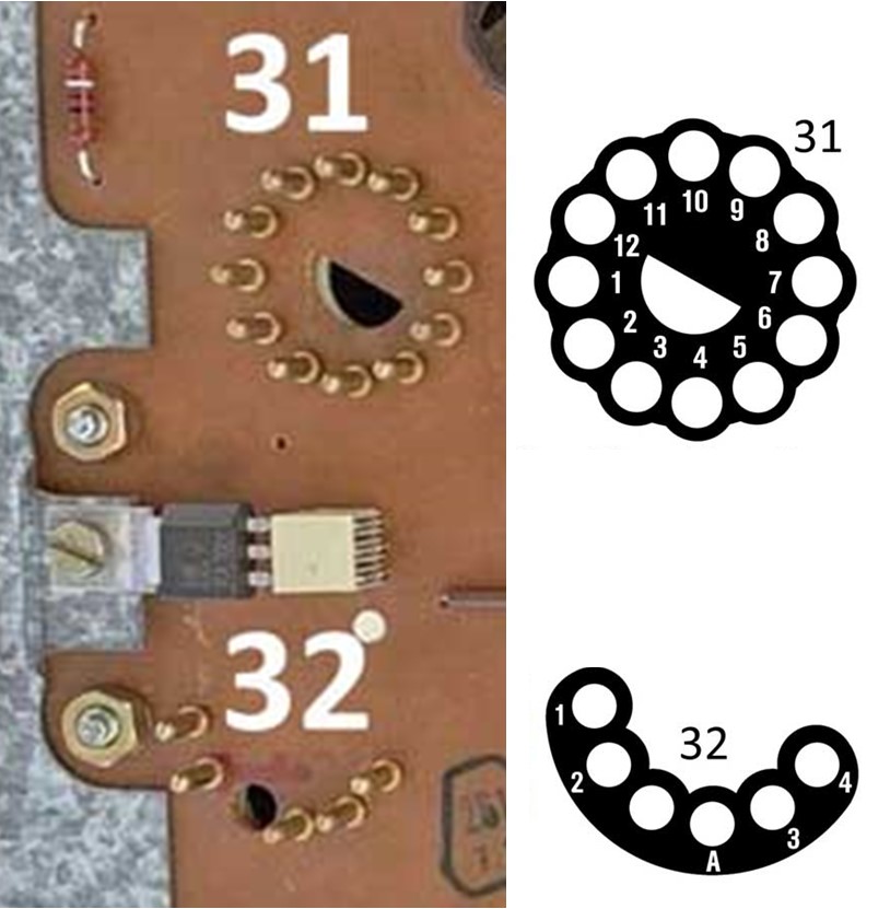 MORE INFO on cluster regulators: turbobricks.com/another-temp-gauge-problem.351447/ SEE THE BELOW VIDEO. 1984 Volvo 240 Cluster Circuit Board and Voltage Regulator: https://www.youtube.com/watch?v=CwJawHImVns&t=11s
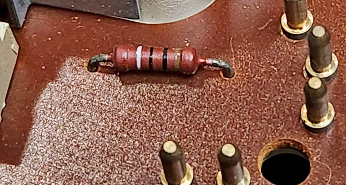
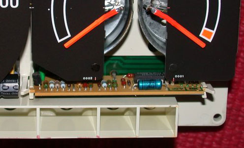
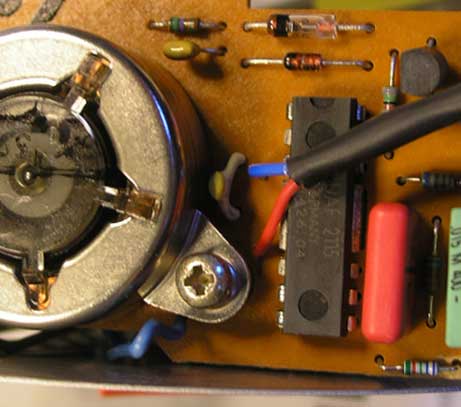
This is a 1984 240 Turbo circuit board. I thought that resistor needed some explanation. The best educated guess on the function of this 10 Ohm RESISTOR is that it offers some measure of fused protection to protect the voltage regulator or other components. I'm not a pro at electrical engineering, but when I measured resistance on this burnt resistor, which I found on a spare cluster board I was testing, I got a reading of 7.35 kOhms (7,350 Ohms). Some people initially thought the markings designated this resistor value as 90 Ohms (White, Black, Black, Gold), but later info suggests it's actually a 10 Ohm resistor, reading from right to left as Brown, Black, Black, WHITE (the white band may be a substitute for Silver or possibly a manufacturer specific marking). The 10 Ohm value is presumed correct, since I later tested a known good resistor in a different non-damaged board and I got a reading of 10.3 Ohms. Clearly the burnt resistor was faulty. 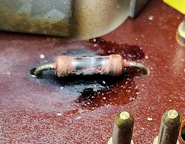
 The REVERSE side of the ground path to this resistor is shown below. 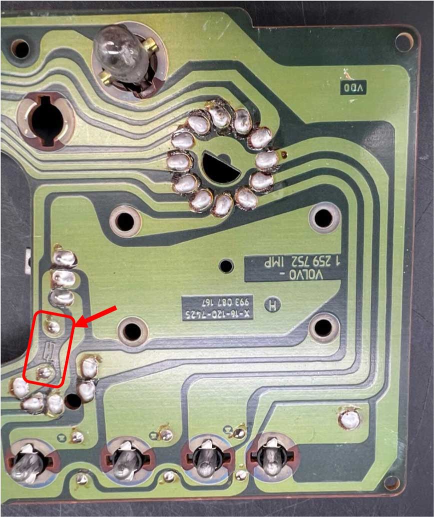 Finding this same Ground Path Resistor in a 1986 or Later Cluster These circuit boards changed for 1986 and later years. For some later clusters you might find this resistor as shown below on the 1990 cluster, but it's absent (or moved elsewhere?) in the 1986 cluster. 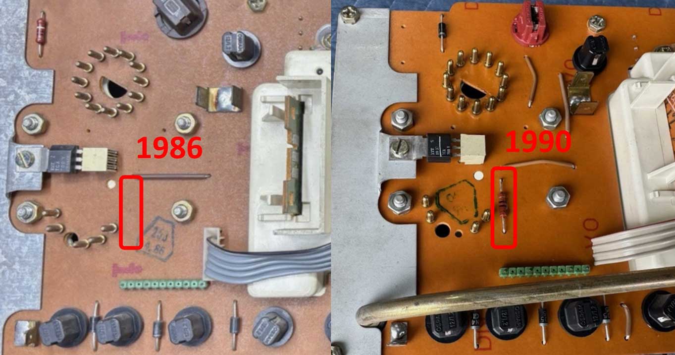 This discussion involves the OPTIONAL REPLACEMENT OF THE 10V REGULATOR WITH SOMETHING DIFFERENT. This rabbit trail began after I found problems with the spare instrument cluster shown above (with the burnt resistor). While testing the spare 1984 240 instrument cluster to get some temp gauge voltage values ( It was for THIS TEST HERE in my Brushless Fan Page), I found the original 10v regulator wasn't regulating correctly. Instead of it feeding a stable 10v to the temp and fuel gauge, it was only reducing voltage slightly from about 13v to about 12v. Plus it wasn't offering stable voltage at all. Chief symptom: If voltage was increased at the gauge cluster input, the VR output also increased. This is not good if you're expecting stability. So I bought some new L7810 VRs and installed one. Testing again I found the new VR function was no better than the old one. This told me that the old VR might not have been bad. Maybe something else was going on. LATER UPDATE: After doing this VR modification below, I later acquired a different gauge cluster board, which had a confirmed GOOD RESISTOR. That board seemed to be working as it should without needing any attention as mentioned below in this article. So modifications like this may be unnecessary or academic for most clusters that are in good working order. Some notes about Coolant Temp Sender VDO/Volvo PN 460191. This sender image below represents the original factory calibration numbers. This should be consistent if you're using a FACTORY VDO/Volvo part. You should know that if you purchase an FAE aftermarket sender (available from iPd), that it's not calibrated the same. On later cars with functioning temperature compensation boards, this may not be noticeable, but on early cars or on cars with bypassed compensation boards, an FAE sender will put the needle slightly higher at operating temperature. 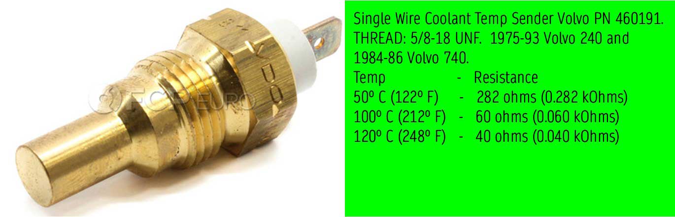 Side Note about my experience with BAD Used Volvo Senders: My car uses this VDO Volvo sender above. I had two used ones in my parts bin, which I was pretty sure worked just fine when I got them years ago. I tested them with an Ohm meter, but I couldn't get any readings. It was like the sensors weren't connected inside. I questioned my Ohm meter until tried a different meter. Then I ordered a new sender and it worked just fine. More on this project is in my Brushless Fan Page. So does it matter if your temp (and fuel) gauge is getting more than 10 volts? I did a lot of testing for my planned brushless fan controller installation in THIS PAGE. The tests were to measure the voltage output at different temps from the factory 240 temp sender to the temp gauge. I needed this info to be certain of the setup on a brushless fan controller I was using, which would be controlled by my Volvo temp sender. I knew that if the main voltage INPUT to the temp gauge became higher than 10v, the gauge would be inaccurate, so a working voltage regulator was important. These tests gave me a better idea of how far off it could get if the VR was not working. I would not have expected this to be so critical, but the difference is fairly substantial. For example, if 13v was coming to the into the cluster power input from your running car charging system, the temp gauge should only see 10v if the regulator is working. But with a faulty regulator allowing more voltage (like maybe 12v instead), the temp gauge would read higher than normal. At a lower coolant temperature the difference was pretty small, but as temps increased and got closer to or above 180° F (needle at about mid-gauge) the needle began showing a lot higher than normal. If the sender got to 200° F the needle was almost 25% higher than normal. So this should tell you how important stable voltage is. THIS IS THE WIDGET MAN ADJUSTABLE POWER SUPPLY 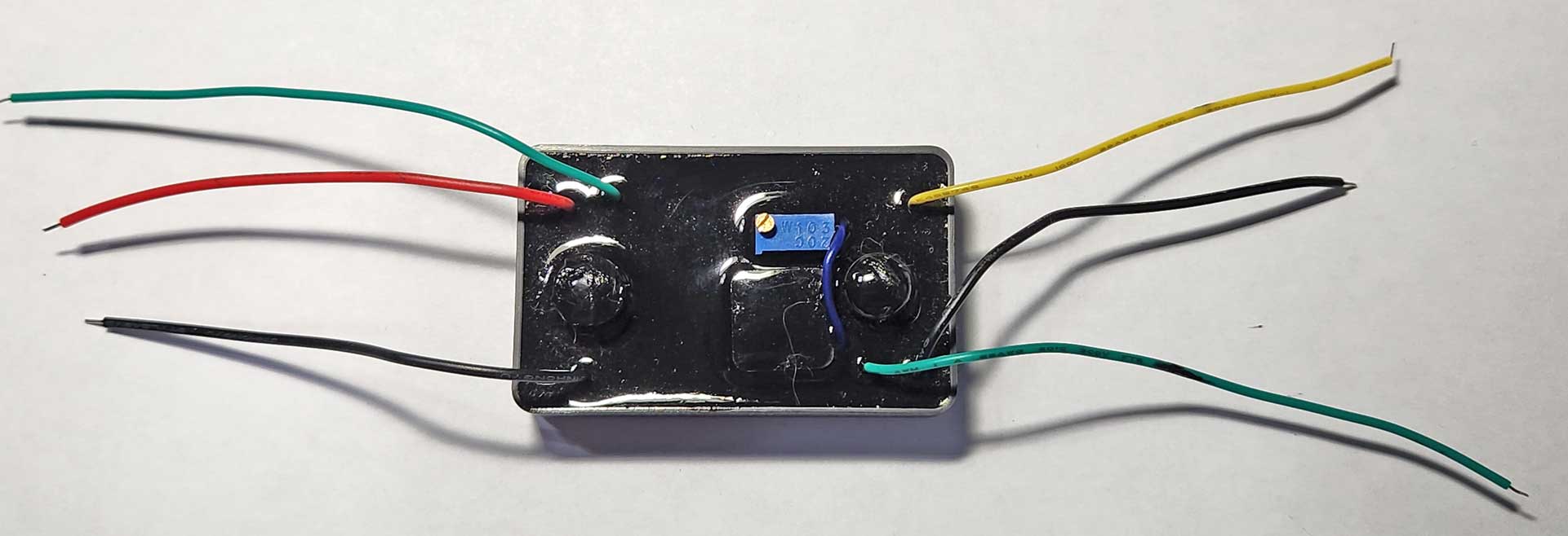 https://gkgoodcheapparts.com/products/adjustable-sensor-power-supply-with-built-in-pullup-resistor This device can be used to provide a stabilized voltage level for any 12v device as long as it's consuming under 1 amp. This item is typically referred as a "CTAS" in Widget Man literature. It has an adjustment screw, so it can be set for any voltage output level between 1.25 and 12.55V. A stabilized voltage output level may not be needed for every car, but if you find that your car system voltage can rise or drop more than a few tenths of a volt with load changes, then it can make sense to provide a stable voltage level to certain devices for better accuracy, like the temp gauge. For this particular use on the 240 instrument cluster, this power supply would be used to replace the original VR, so the cluster would actually have a solid, consistent and stable 10v to the temp and fuel gauges. In this diagram below you can see only three wires on the Widget Man power supply are used. 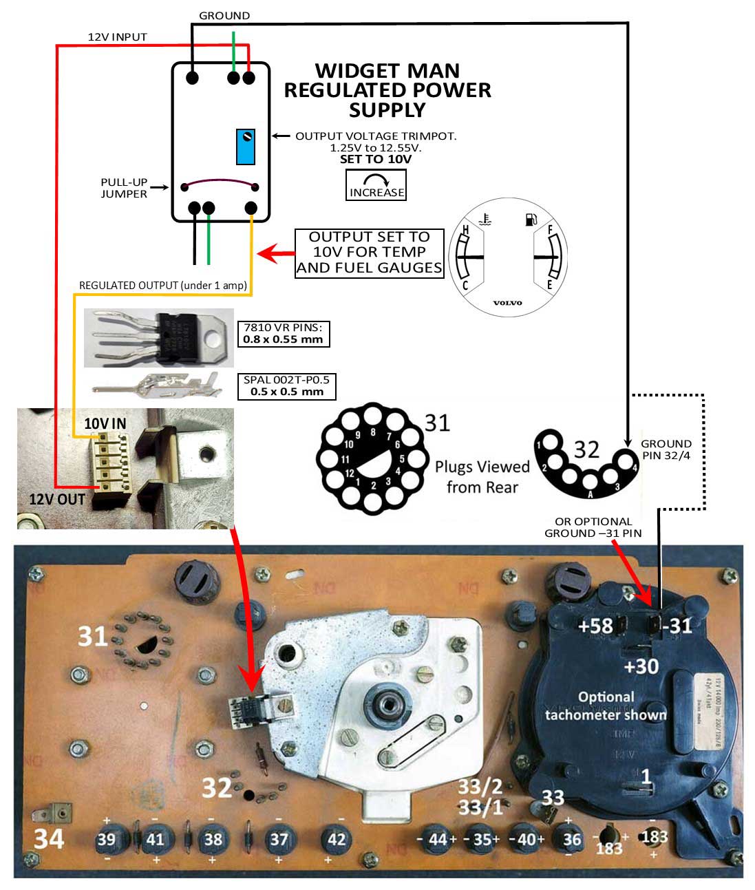 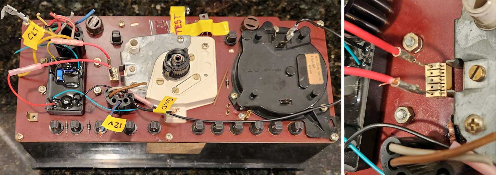 Can you see the original white socket above that was previously used by the original VR? When I hooked things up I used only the two OUTER pins. One is INPUT and one is OUTPUT. So you might ask, why did I NOT use the center GROUND pin? The reason is that when I checked that center GROUND pin for continuity with the cluster ground (Connector 32, pin 4), no ground was present. So instead I used a different ground (Pin 31 is also a good ground to use if needed). I later determined the reason the center ground pin didn't have continuity is related to that BURNT RESISTOR mentioned earlier, which is inline between that center pin and the main cluster ground. LATER UPDATE TESTS: I later acquired a different used circuit board, which had an INTACT resistor. When I tested continuity on that board for the ground path through the resistor, continuity was PRESENT and perfect, as it should be. |
|||
|
|
|||
|
Temperature Compensation Board Bypass or other fixes for your 1986-93 240 gauge cluster. |
|||
 To make customers feel better, beginning with the 1986 year model, Volvo began installing a special circuit board in the instrument cluster that changed the function of the coolant temperature gauge so that it would remain stable in the middle or appear more "normal" at all times unless the engine was ACTUALLY very cold or very hot. The gauge needle then had only a few programmed readings instead of a true variable reading. Then it appears that customers were happier with a gauge that didn't reveal the true temperature. These temperature compensation boards generally worked fine until they got old and began failing. A failing board would cause mysterious high or low fluctuations for no reason. If you're trying to determine what your high or low temperature fluctuations REALLY mean, you can get an infrared (IR) temperature reader and check your top radiator hose temps or your thermostat housing for abnormal changes. If you find that actual temperatures are pretty stable, then your temperature compensation board may be the problem. Below image from TP30778/1 New Car Features 1986 240  This somehow would not offer ME much comfort after reading THIS. North American Market versus European Market in 2024 I was sent some images below showing a 1988 240 gauge cluster board from a European 240. The Euro 240 board was obviously never made to accept a temperature compensation board. I don't know for certain if this is typical of non-U.S. 240s, but it certainly appears possible.  BYPASS STEPS This image below has circulated the net for a while. It shows some simple steps needed to remove and bypass a Temp Board. 
Here's a fuzzy old video showing this board being removed:
https://www.youtube.com/watch?v=xpyFEWoqiaE
|
|||
|
As of this writing these stabilizer boards can still be found new, however they're expensive. iPd was offering them here: ipdusa.com/voltage-stabilizer 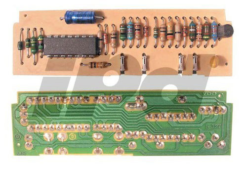
|
|||
You can also read the following instructions for
your own DIY Compensation Board BYPASS . . .
ARTICLE HERE: https://cleanflametrap.com/tempFaker.html And if your interested in more DIY repair, Peter A. submitted the following: "The circuit is kind of clever. It can be repaired rather than just eliminating it. It does require a soldering iron and a solder sucker to de-solder the old parts. Pretty much the only things that will fail is the integrated circuit U1 or output transistor Q1, both of which can be purchased on-line from Digikey or similar places for about a dollar. U1 was bad on my board. After 25 plus years it would also be wise to replace the electrolytic capacitor C1." Click here for a PDF diagram and photo of these circuits: https://www.davebarton.com/pdf/TempBoardCircuits.pdf (270kb) And Dirk W. submitted the following for those interested: "Lots of people will claim you need a new temperature compensation board (PCB), but that's not what's really wrong most of the time. I have found that the metal pins that are mounted to the main cluster PCB are generally not properly soldered to the PCB. They APPEAR to be soldered, but if you touch a soldering iron to the solder blobs that cover the heads of the pins, you will find that the solder is not wetted to the pin heads and these connections are almost always bad somewhere. A little work with some sandpaper on the heads of the pins and resoldering the heads of the pins to the PCB will fix most temperature gauge issues." |
|||
| 240 Electric Speedometer CUSTOM Re-Calibration Tricks | |||
|
(Applies
to 1986 and later 240 electric speedos. 700/900
models too)
This information has been compiled
from discussion threads in Turbobricks, Brickboard and from customer
contributions. It's a relatively simple mod, but
some clarification was needed to make it
simple for the rest of us. Using modern
electronics, you may add a variable
trimpot (rheostat) to alter or adjust the
signal the speedometer receives from the
vehicle speed sensor (VSS) in the rear axle.
First thing you'll need to do is
disassemble your instrument cluster and
remove your speedometer. If you
don't know how, instructions for that can
be found in my 240 Odometer
Repair Page.

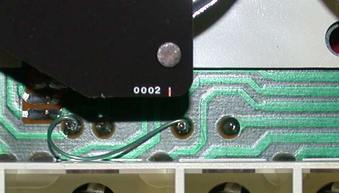
 Depending on the year of your 240, you'll see a resistor like one of these two photos above. That is the calibration resistor. It is static (or non-adjustable). It was installed by Volvo to alter the speed signal for the specific speedometer and tire size they selected for your car. The original resistor has been measured by others at around 51 to 56 ohms. By changing the value of that resistor, you can change the speed signal received by the speedometer. Some have installed different static resistors to reset their calibration. A few have installed variable resistors so the calibration can be fine tuned when driving. That's what this article is about. 1. Using a soldering iron, heat the solder behind the original resistor and remove it. Simple task. |
|||
|
2. Next
insert a stripped wire into each hole and solder
them on the back so they're secure. You may use
18 to 22 gauge wire or smaller. If the
holes need to be opened up a little, use a very small
drill to do that, then solder.
 |
|||
|
3. Here is
an example of a 100 ohm variable resistor
(adjustable between zero and 100 ohms). A
"linear" type is preferred. These can be
found on eBay or Amazon and are very cheap (usually made
in China). Often they're offered in lots of 5 or
10 for under $10. Feel free to put an ohm
meter on it and find the two pins needed for the
wire hookups. Polarity is not
important. While you're at it, set it
somewhere in the middle (50-55 ohms).
 |
|||
|
A customer sent this pic below.
He mounted the variable resistor behind the hole formerly occupied by the clock adjuster. This way he could tune it easily after the dash was assembled and it looks very clean. There's no need to get this fancy if you don't want to. The resistor can also be put under the dash or anywhere within reach depending on wire length. 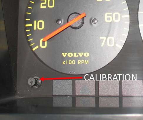 If you can offer any new information or better ideas for this mod, please email. |
|||
| Resources for more info:
https://www.brickboard.com/RWD/volvo/853622 turbobricks.com/240-electronic-speedometer-calibration-1986.239021/ turbobricks.com/modifying-speedo-for-use-with-t5.258248/ |
|||
|
Other Resources for Adapting Mechanical (cable) Speedometers to serve Electric Speedometers or vice-versa. Beginning in 1986 Volvo began using a Vehicle Speed Sensor (VSS) in the rear differential (ABOVE IMAGE). This was a 2-wire Variable Reluctance (VR) type sensor, which would read the speed of a tone ring mounted on the differential carrier. More info about these sensors and tone rings can be seen in my 240 Rear End Page. In this section below I'll list some options that are relevant to making conversions work. Some of these devices further below are quite expensive. Some are not. If you have used any of these products for a conversion (or similar products), I would like to hear from you so more of these solutions can be shared. ------------------------------------------------------------------- One workaround if you have a cable speedo car which needs to generate a VSS signal for an LH 2.4 ECU, can be found in my Harness Conversion Page. This conversion has some steeper limits, because it requires using old speedo parts scavenged from other gauge clusters. As used 240 gauge parts become more expensive or harder to find, this kind of thing becomes harder to do. Click Here: prancingmoose.com/#speedopulse -------------------------------------------------------------------- This first entry below is from my most recent research. If this stuff interests you, you should know some of it may need a little bit of experimentation to prove it works as expected. This discussion mainly involves an early 240 which DOES NOT have a VSS in the rear differential. The goal is to create a VSS signal to operate a later electric speedometer and/or provide a VSS signal to an engine management ECU, such as LH 2.4. Some of the more expensive devices further below can supposedly do this kind of thing too, but this particular discussion will use some way less expensive ideas and readily available parts.  This thing above is a Universal Speedometer Corrector (USC) offered by Widget Man Parts. It's available on eBay, direct link here: https://gkgoodcheapparts.com/products/usc-univeral-speedo-and-tacho-corrector It can also be found in their catalog here: https://gkgoodcheapparts.com/collections/all. The price at time of writing was $59. This device may seem conspicuously inexpensive and you might be a skeptic, but after I used a few of their other devices for my Brushless Fan Project, I can tell you that I was very impressed with the function and quality of their stuff. This USC has a number of versatile functions. If you dive into their instruction pages you'll see quite a bit. This conversion will incorporate a universal Hall sensor to provide the needed speed signal. 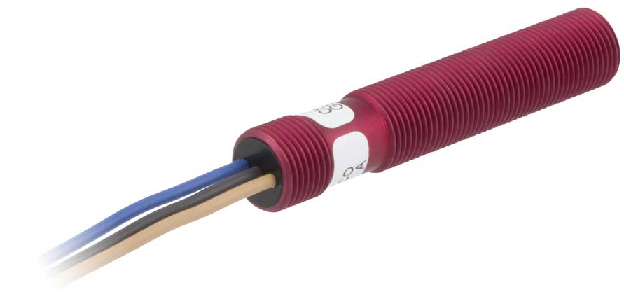 This is a ZF Electronics GS100502 Hall sensor (formerly known as a Cherry Switch). You can find them online everywhere for as little as $30. It has three wires. The threaded barrel is M12 x 1. The ZF DATA SHEET for this sensor can be found at: switches-sensors.zf.com/GS1005-GS1007.pdf This is a robust Hall sensor which is quite a bit less expensive than those listed further below. It can be used as a universal sensor to read speed revolutions from a driveshaft coupling or almost any other rotating part, including bolt heads passing by, as long as the part passing by is FERROUS METAL. You would need to construct a mount for a sensor like this. This video below is not a Volvo and it's not this same sensor, but it will give you an idea about how this can be done. https://www.youtube.com/watch?v=cCB_LO2KymY The data sheet above recommends a distance from the rotating target of 1.5 mm. A raw signal from this sensor is not compatible with the Volvo speedo, so this is the reason for using the Universal Speedo Corrector to interpret the signal. Here's a diagram I made with assistance from Gene at Widget Man Parts. Please let me know if you try this. 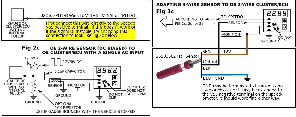 If you can offer any comments or if you use any of these devices, please let me know how thing worked out or if you used it differently from how it's shown here. Here's another device from Widget Man. This is a Dual-Channel Inverting Zero Cross Voltage Converter It's designed to mimic the +/- AC signals that would come from a 2-wire magnetic reluctance sensor in case that type of sensor interests you. It can be used with virtually all 2-wire crank position sensors or cam sensors. 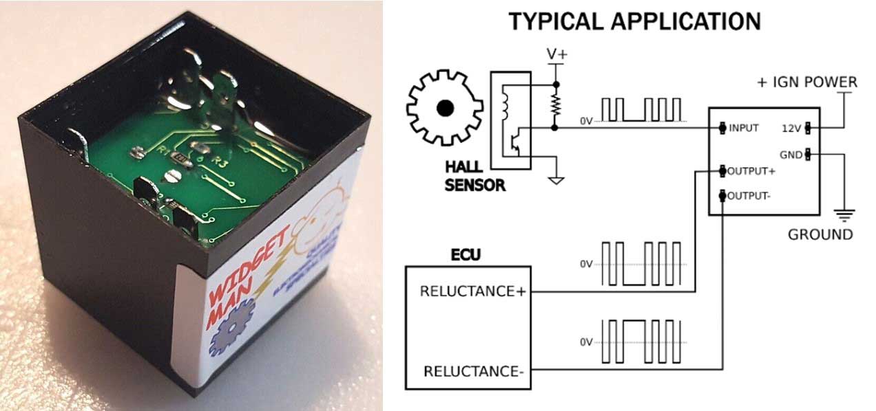 It's available on eBay, direct link here: https://gkgoodcheapparts.com/products/widget-man-pmc-2-channel-reluctance-sensor-simulator-true-ac-voltage-output It can also be found in their catalog here: https://gkgoodcheapparts.com/collections/all More Devices to look at if needed:  SGI-100BT: Universal Speedometer and Tachometer Interface From Dakota Digital. This box can adjust, split or recalibrate an existing electronic speed signal, or re-calibrate a tachometer signal. It does not come with a sensor. dakotadigital.com/prd1192.htm 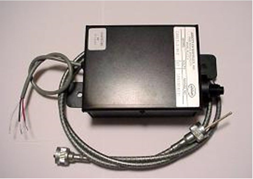 This is Cable-X. This box lets you use the most common OEM electronic speed signals to spin and run a mechanical cable-driven speedometer. http://www.abbott-tach.com/cablex.htm  ECD-200BT: Electronic Signal to Mechanical Cable Drive Adapter from Dakota Digital. It allows you to use an OEM VSS signals to spin a mechanical cable-driven speedometer. https://www.dakotadigital.com/prd886.htm 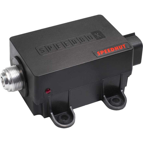 Speedhut Electric to Mechanical Speedometer Cable Drive Conversion Boxes. Uses an electronic pulse signal or may use a GPS speed input from a GPS Antenna (sold separately). https://speedhut.com/categories/speedbox.html  Speedometer Pulse Signal Generator to create a signal from an existing speedo cable. https://www.dakotadigital.com/prd109.htm  Universal Inductive Speed Sensors to create a custom speed pulse signal from a driveshaft or other rotating device. https://www.dakotadigital.com/prd246.htm  Driveshaft Universal Speed Sensor (Hall effect) to create a custom speed pulse signal from a driveshaft or other rotating device. It's more expensive, but it offers an LED that lights up as the sensor operated, allowing you to see that it's working. lowdoller-motorsports.com/driveshaft-speed-sensor-m12 |
|||
|
|
|||
| Adding a Simple Large Tachometer to your 240 | |||
|
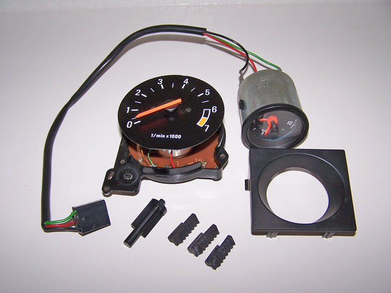
If
your 240 has the large clock, this tach can be installed instead. This is
the very first modification I did to a 240 back in 1990. It's a
very basic
install, but can be a bit puzzling for a beginner. These
instructions will also show you how the small clock is
installed.
|
|||
|
|
|||
| Adding an Oil Temperature Gauge to your 240 | |||
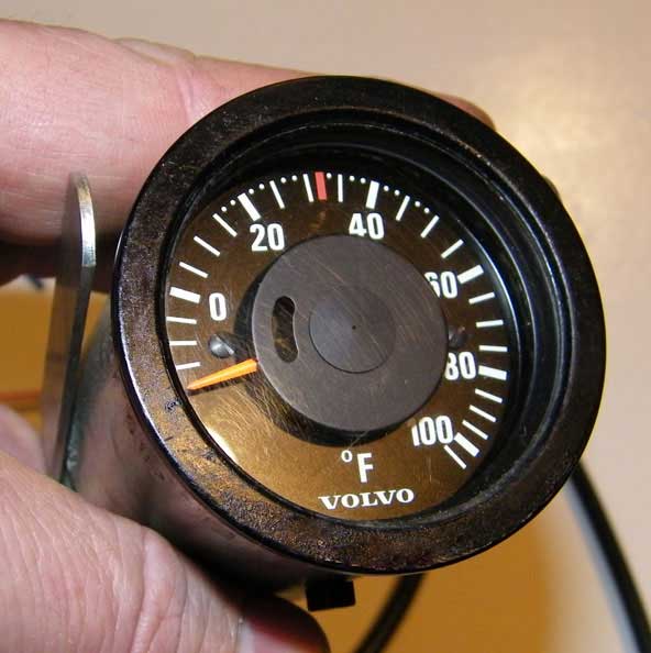
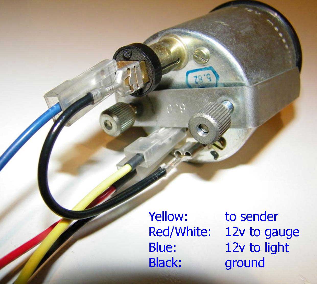
| If yo
u would like to install an oil temperature gauge for your 240, here are some details. The 240 oil temp gauge will most commonly be found in Celcius, however Volvo also offered it in Fahrenheit 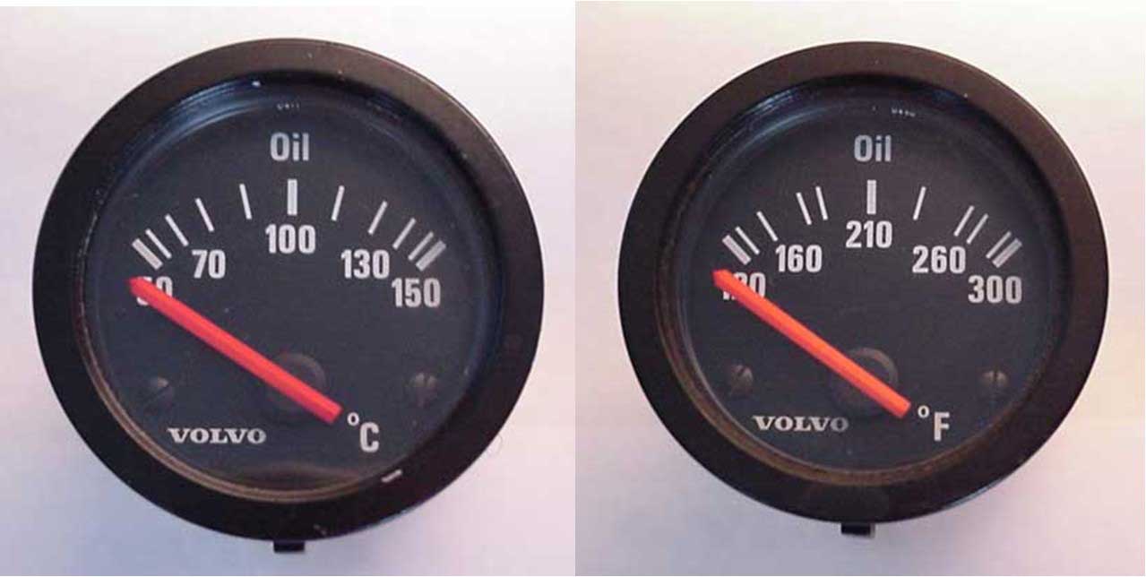 Other than the lamp, there are three gauge connections on the back. Ground and switched 12v, nothing unusual about those. The G terminal is connected to the temp sender 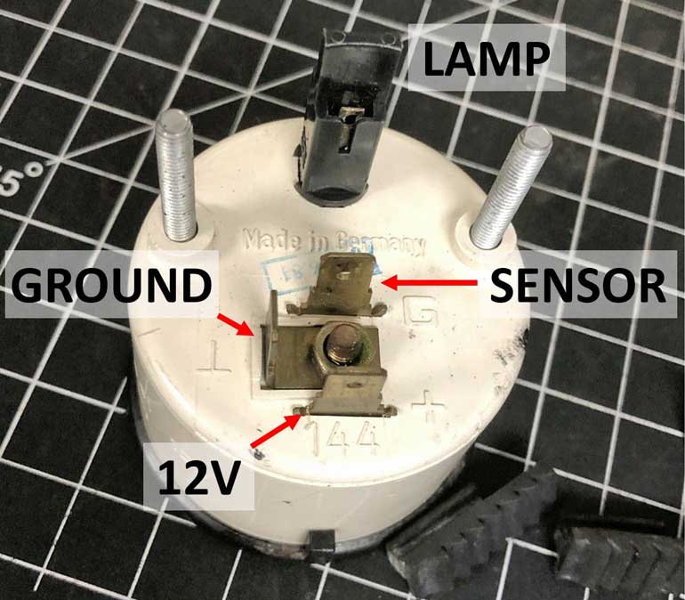 The original temp sender, made by VDO, was designated for the 150º C gauge (the 300º F gauge uses the same sender). It was specially made for Volvo with the correct thread (3/4-16) to use as an oil drain plug. It's still possible to find used original senders, but they can get beat up over the years like this one below.  Original sensor drain plug like this above have been no longer available for many years. 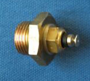 You can sometimes find custom drain plugs like this ABOVE that have been custom converted with a new temp sensor installed. Of course, there are some (including me) who don't particularly prefer having an oil temp sender sitting so low to the ground with no protection. I can tell you that on a lowered 240, the chan ces of eventually destroying it are high. In 2021 I decided to install a sender in my remote oil filter mount. You can see that in my Oil Cooler Page: 240turbo.com/oilcoolersender. 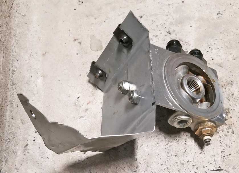 . |
|||
| Adding a SMALL Tachometer to your 240 | |||
| While less popular than adding a large tachometer to
your gauge cluster, Volvo made a small 52 mm tachometer
available for 240 owners. They are fairly rare to find these days, but they can still be found used. Here are diagrams for wiring it up. CLICK HERE FOR INSTRUCTIONS (pdf)  |
|||
| Adding an Ambient Temperature Gauge | |||
| This should help if you're installing one of these. |
|||
  |
|||
|
|
|||
| REPAIRING A DEAD 52 mm VDO CLOCK | |||
|
If
you have a dead small VDO clock, you can repair
it.
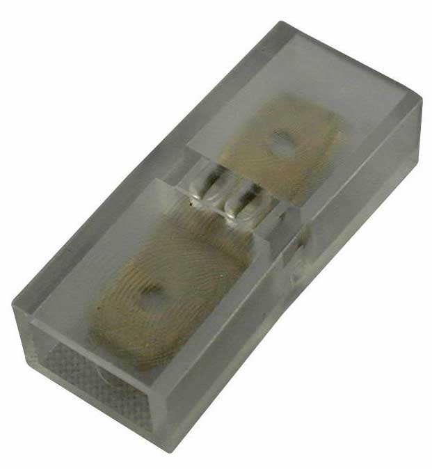
There are two small capacitors inside the clock that often fail after many years. They're cheap to buy and fixing is fairly easy.
|
|||
If you have a 1980 or older 240, here is some info below specific to your early 240 clock:  https://ozvolvo.org/repairing-clock turbobricks.com/early-style-240-clock-repair.280520/ |
|||
|
|
|||
|
Dash and Gauge Lighting. Improving Lighting in Clocks and other 240 Gauges |
|||
| DIMMER RHEOSTAT BYPASS OR INSTALLATION In my car I removed this dimmer years ago and have been happy with lighting since. If you have noticed weak, dim dash lights in your 240, even when the dimmer switch is turned to full brightness, you should know this rheostat switch will not provide full power to the bulbs, even at the full brightness setting. If you want to verify this, hook up an Ohm meter and check the resistance and you'll find that the dimmer supplies significantly less current at full brightness than if the lights were simply wired directly. If you bypass the dimmer and then your dash lights will be either off or full bright. You will nee to bridge the two connections on the back of the dimmer (see pics below). If you're not sure if this is right for your car, try it temporarily are see how you like it. You'll find that after bypassing the dimmer, all of the gauge and dash lights will be brighter. If you keep the dimmer, you just need to decide if using that dimmer switch is worth having less than full brightness. Access to the back of the dimmer can be done by removing the main instrument cluster and then you can reach in and do your work. |
|||
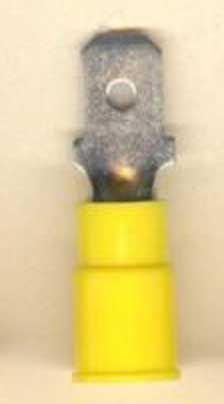
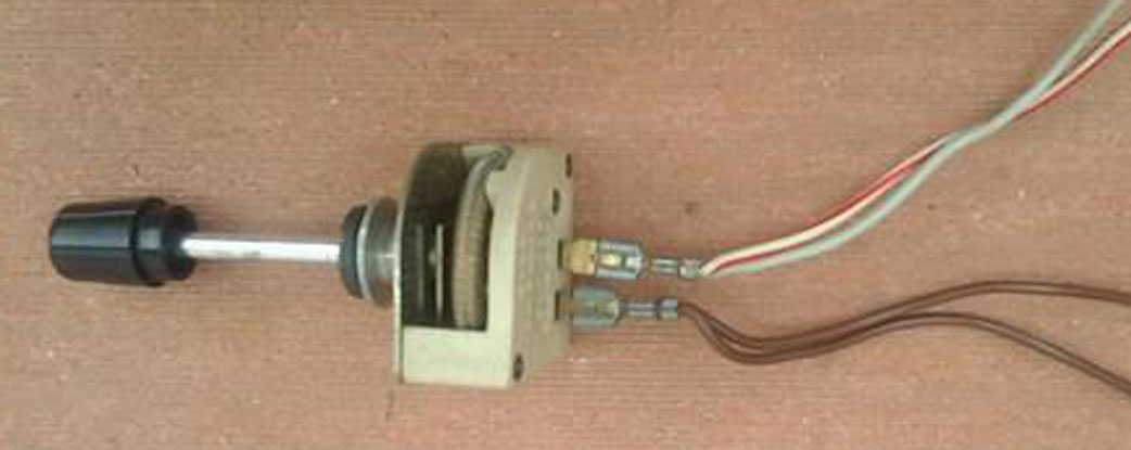  The two .250 inch female terminals at the rear of the dimmer can be unplugged and then bridged together. A simple way to do that is using a double male .250 inch connector or a couple of .250 inch male push-on terminals with a wire crimped between them. Just about the easiest mod ever, which can be reversed easily if needed. Just make sure these terminals are insulated from accidentally touching metal or you'll blow a fuse. |
|||
 If you later decide to RESTORE your dimmer, it will be simple. Just plug one wire terminal into one side and the other wire terminal into the other side. The wiring order is not important.They can be connected either way on a rheostat like this. If you're curious about where those wires go, this info below comes from a 1990 240 wiring greenbook. GRAY: 12v input from Fuse 16 (12v from Headlight Switch when ON). WHITE-RED: Output to lamps for Fasten Seat Belt lamp and Ashtray Lamp. BROWN (2 wires): Output to instrument lighting and floor gear selector lamp (if auto trans is present). |
|||
|
|
|||
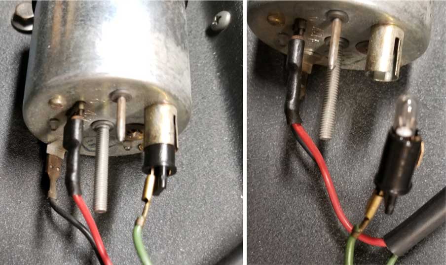
| CLOCK or other Instrument Lighting The bulb is found in this black plastic bulb holder on the back side. In this instance there is only one wire going to the bulb. That's the power wire. The bulb is grounded through the clock metal case. So when you're testing a bulb in a clock like this, be sure to ground the case. The ground wire is the BLACK wire seen in the first photo below which is connected to a tab on the case. |
|||
 |
|||
|
|
|||
|
VOLVO GAUGE BULBS This is the standard bulb found in the above clock. It's known as a WEDGE BASE BULB. 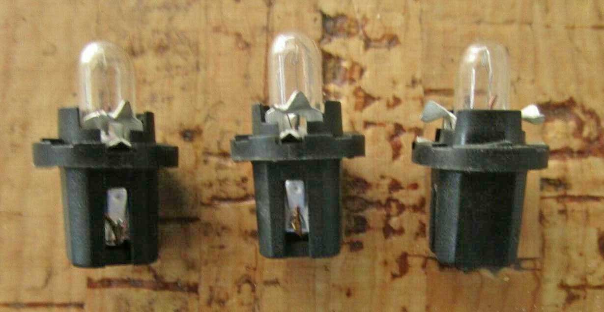
This particular bulb may be known as: Type 74, T5, or Osram 2721. The Volvo parts catalog identifies it as PN 942327 or W2X4.6D. This Type 74 bulb is usually 1.2 watts. One other use is in the 240 main instrument cluster for the turn signal lamps below. 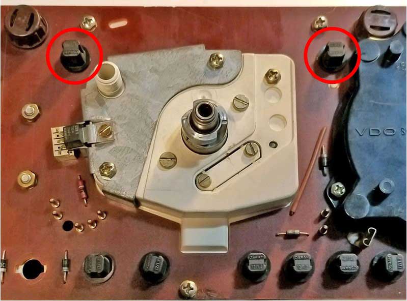 The Type 74 bulb above is NOT the same as a larger wedge base bulb shown BELOW used to illuminate the 240 instrument cluster (1984 cluster shown). 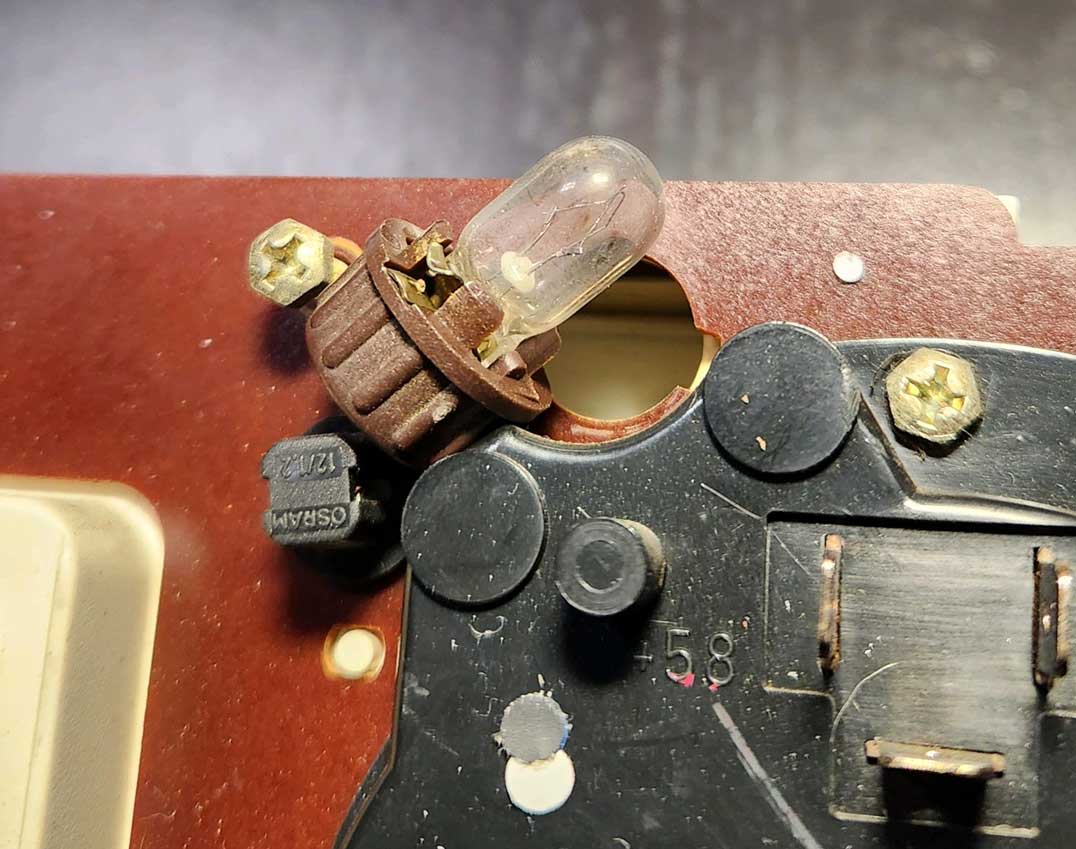 This larger bulb (without socket) is PN 942571, AKA: W2,1X9.5D (rated at 3 watts) or PN 1259950-2, AKA: W2,1X9.5D (rated at only 2 watts). This socket without bulb is identified as PN 1259770 or 1214665. The above 74 bulb is very similar and may often be interchanged with PN 19923-2, AKA: BA7S (rated at a brighter 2 watts). These are typically found in some 52 mm gauges and also used in various places in the 240 DASH CENTER CONSOLE for general illumination. A brighter 2 watt bulb may be used in place of a 1.2 watt bulb for dash lighting, but it may not be the best idea to use a higher watt bulb where a warning lamp is used. The small bulb socket shown above are 240 cluster warning lamps. These bulbs are identified as PN 966326, rated at 1.2 watts. The small plastic socket above by itself is PN 1308634. A typical WEDGE BASE BULB will likely simply pull out of the plastic bulb socket. If it's stuck, it could be from years of corrosion and it just needs more force to pull it out. Some are so stuck they will not come out without destroying the bulb, which makes me guess that some might be permanent. If it seems hopelessly stuck, you might wear gloves, because you might cut yourself when the bulb breaks. |
|||
|
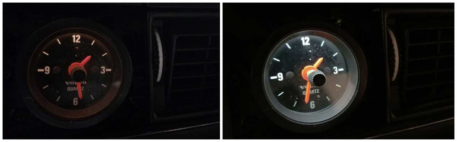
LED BULBS Here's a comparison test below for a wedge base LED bulb I picked up on line for the clock. The brighter photo below is with the LED bulb. Keep in mind that all LED bulbs have a specific polarity, so if you plug one in like this and it doesn't work, try pulling it out, turning it 180 degrees. |
|||
  |
|||
| Your
results may vary. Some cheap Chinese LED bulbs have crappy
quality and
it's hard to know what's good and what's not until you try it. Sometimes
you can read Amazon reviews if you think they're trustworthy. I've
tried LED bulbs for a few various places in 240s and some have worked well
and
some have died quickly. The LED bulb used above is found here: amazon.com/B0798R76CR/ |
|||
| Here are some more links for useful info on this subject: turbobricks.com/led-in-240-cluster-gauge-installation.148807/ |
|
||||
| davebarton.com |
prancingmoose.com |
240turbo.com |
Special Emblems |
|
| Prancing
Moose Stickers |
Volvo
Stickers |
Body/Chassis/Engine
Labels |
240 MODS and FIXES Page | |
| Other Car Brand
Stickers |
Steering
Wheel Labels |
Center Cap Labels/Overlays |
Cool Volvo
Products |
|
| Grill Labels/Overlays |
Volvo Wire
Harnesses |
Conversion Harnesses |
Harness
Parts/Connectors |
|
| Volvo Relays |
Coil Repair
Harnesses |
240 Window
Scrapers |
740/940
Window Scrapers |
|
| Adjustable Voltage
Regulators |
Horn Buttons |
240 Odometer
Repair |
740 Odometer
Repair |
|
| Volvo Gauge
Faces |
740
Turbo/Boost Faces |
240 Black Door Vinyl |
850 Odometer
Repair |
|
| ALTERNATOR Page |
240 Power Mirrors - Switches |
240 Oil Cooler Page |
240 Fuse Panel Page |
|
| Group A
Racing 242 Turbo Page |
240 Hydraulic Clutch | Fuel Pump RELAY Page |
240 Headlight RELAY Page |
|
| Used Parts & Extra Stuff for sale |
CRIMPING Page |
240 Ignition Page |
240 Headlight Page |
|
| 240 Gauge Electrical Diagrams | 240 REAR END Page | Yoshifab Catch Can Install | 240 TAILLIGHT Page | |
| Side Marker
Lights Page |
Gentex Mirror Upgrade | Yoshifab Drain Tube Install | Modified 240 Favorites | |
| SoCal Salvage Yards | Unleaded Racing Fuel | B26FT Stroker | Dave's 245 Spec Page | |
| 240 SUSPENSION Page | 240 Lowering Page |
240 Windshield Page |
240 WIPER Page | |
| 240 BRAKES Page |
240 Dash Top Gauge Pod | Cadillac 4-Note Horn Install | 240 DYNAMAT Installation | |
| 4 Speed Fan
Controller |
Electric Cooling Fan
Page |
BRUSHLESS Cooling Fan Page |
Tropical Fan
Clutches |
|
| 240 AC Page | "KOMFORT BLINKER" Upgrade | T5 Trans Conversion Page | 240 Engine Mount Page | |
| 240 VIN Page | Stepper Idle Valve Page |
Vacuum Diagrams | 240 HOOD Page | |
| 240 Exhaust Page | 242 Power Vent Window Project |
EFI Volvo Pin Function Diagrams |
Favorite Links | |
| R-Sport
Apparel |
Prancing
Moose Apparel |
Volvo Meet Photo Albums | Texas Volvo Meets and Events | |
| Ordering Instructions | Policies | PAYMENTS Page |
Mojave Road Trail Map Page |
|
| Returns | Shipping | Shopping Cart Troubleshooting | Contact Us |
|

|


 alternators are known for poor voltage.")


