|
2 4 0 T U R B O . C O
M D A V E ' S V O L V O P A G E
|
||||||||||||||||||||||||||||||||||||||||||||||||||


 alternators are known for poor voltage.")


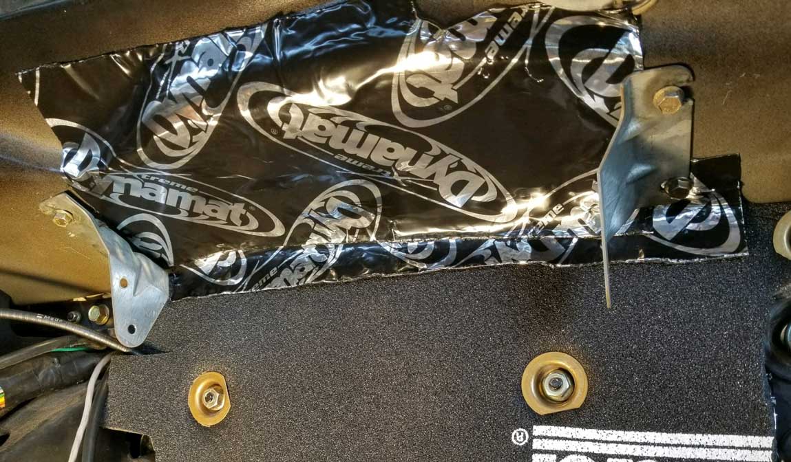
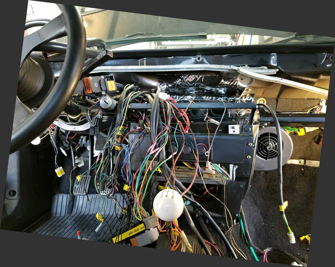
| Before completing my new AC system installation in 2017, I first gutted the interior and installed DYNAMAT. CLICK HERE to see the 240 DYNAMAT Installation Page
|
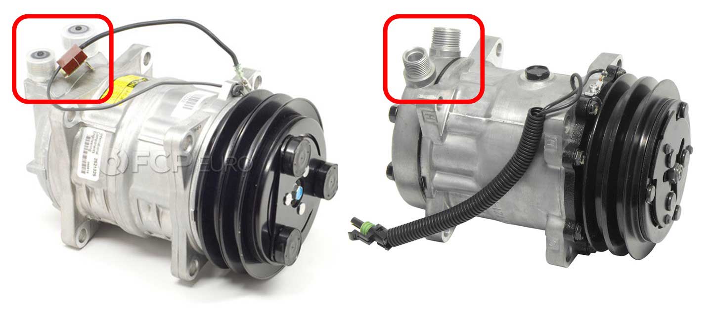
| This
video below can help you to better understand how our Volvo AC systems
work. It does a good job of describing both types (TXV and Orifice Tube
types). He discusses an Orifice Tube type AC he built in a V8 powered
Volvo 245 and a TXV type AC he's building for a V8 powered Jaguar. How To Design And Build Automotive Air Conditioning (1:12 long)
|
| Volvo 240 AC INTRODUCTION and BASICS. |
| I
enjoy taking long road trips. Taking a long road trip in a hot car in
hot climate is not much fun. So when I take a long road
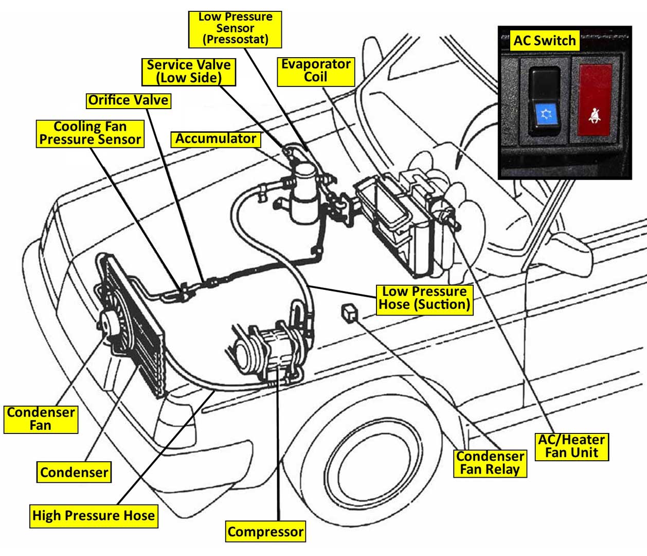
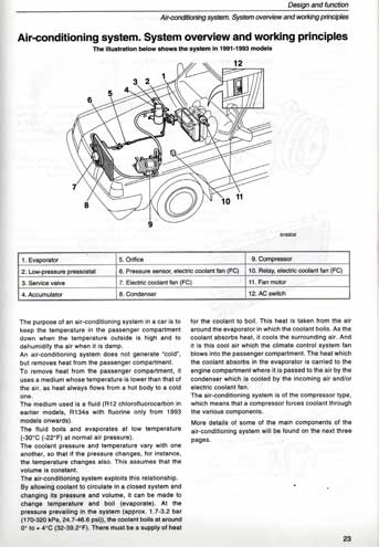
trip, how much better would it be if I had decent AC? Getting satisfactory AC in an early 240 can be a challenge. I sincerely believe the AC systems in these cars were designed with only northern European climate in mind. In my experience, they were almost always a disappointment in warm weather. Specifically in older 240s ( pre-1991) the AC systems were just not up to the task. I don't think Volvo tried very hard for a great result. The 1984 Volvo 240 factory specifications called for AC output temperature from the center vents to be 48-54 degrees Fahrenheit. That's not cold. My idea of cold AC is vent temperatures just above FREEZING. That can be done with enough effort and good luck. Keep reading and you'll see. 240 AC was later improved for 1991-93 cars when a more modern design system was used (more on that later below). Image below shows a pre-1991 240 AC. This can be quickly identified by the AC DRIER on the right fender near the front. 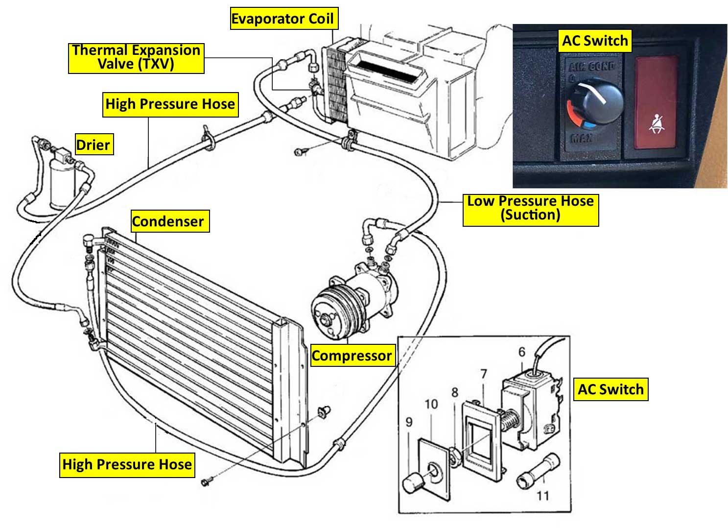
The below photo is from turbobricks.com/ac-fan-wiring-questions.288974/ 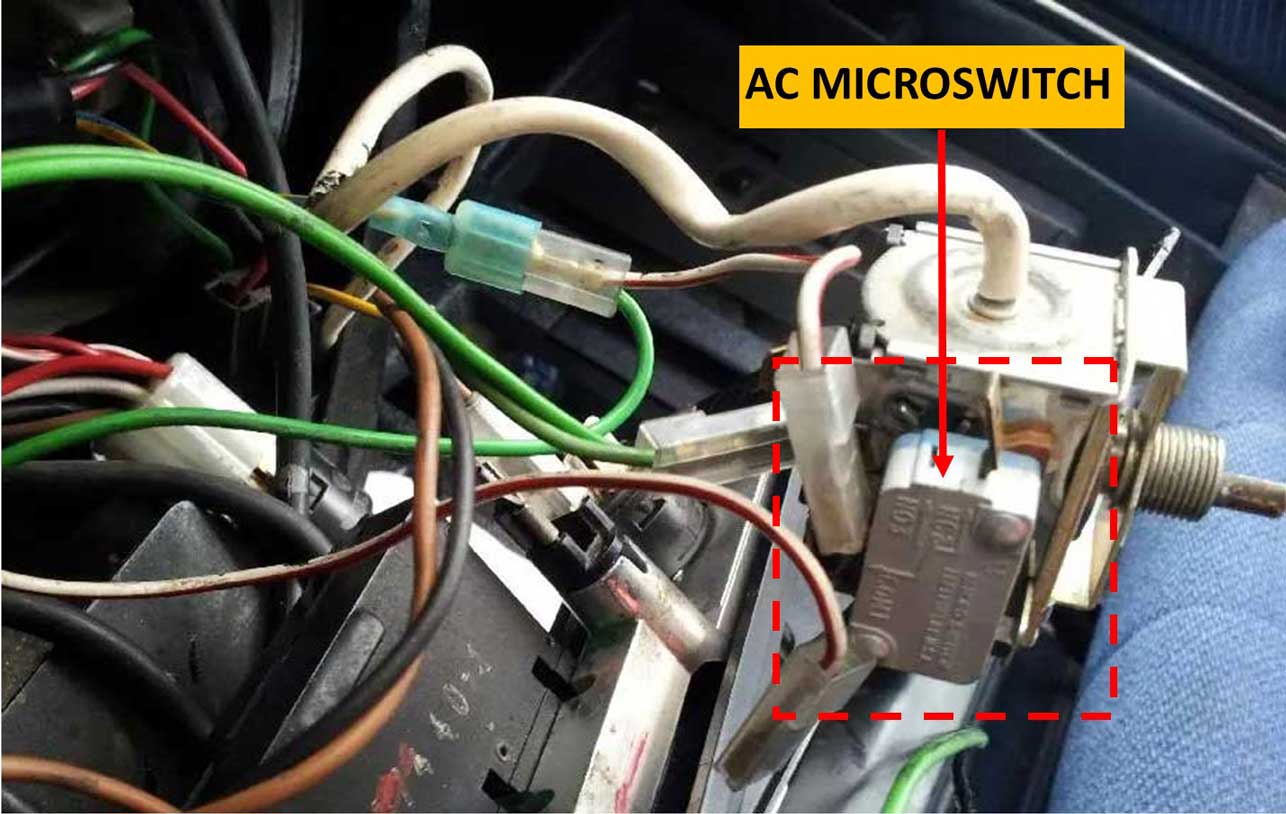 . This AC microswitch appeared in some 1982, and then in most 1983-90 240s. These cars received the above THERMOCOUPLE TUBE style AC switch found in TXV type systems. Pre-1991 AC DIAGRAM Info. The two photos below from the 1985 factory diagrams will help explain. This info focuses on the AC Switch and AC Microswitch. Below the AC microswitch is shown as L or 213. It has a White-Red power wire which comes from the AC switch (B). This White-Red wire is getting power from the GREEN wire that comes from the 10 second delay relay (E or 129). This delay relay came on 1980 and later 240 models. If this relay is present, it provides power to the AC following a 10 second delay after starting the engine. 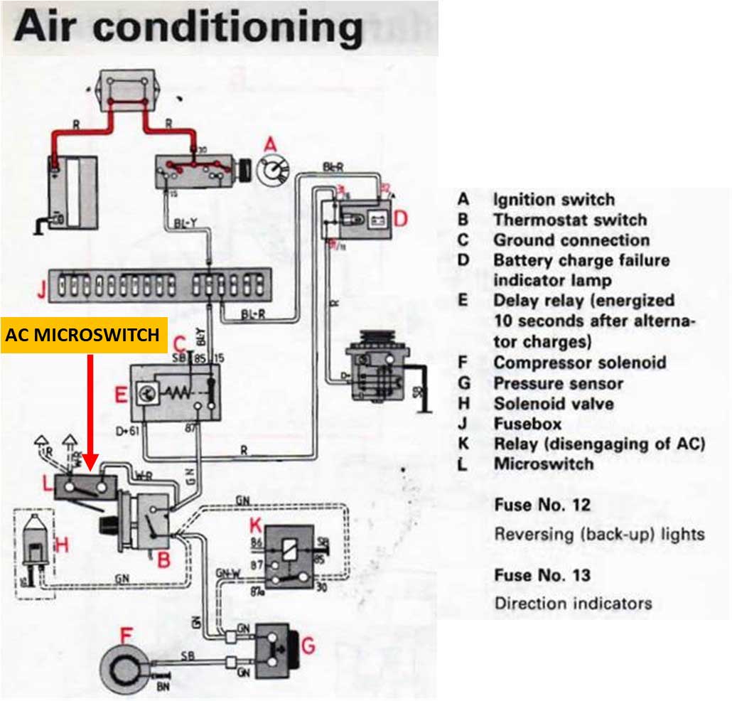 Back to the AC MICROSWITCH (L) above (it's also shown as 213 in the below diagram). It has two power output wires and both split off into multiple wires. In the 1985 diagram BELOW there's a RED wire coming from the 213 AC MICROSWITCH. If the 1985 car has LH 2.2, this RED wire goes to 214/16, which is the LH 2.2 EFI ECU pin 16. This Red wire tells the LH ECU to raise the idle. Before LH 2.2 was introduced, in some earlier cars with K-Jetronic, a microswitch was used instead to turn on a Constant Idle System (CIS) function or it might activate an idle air solenoid valve to raise idle during AC activation. In early cars with no AC microswitch, an idle air solenoid valve is usually activated from direct taken from from the AC compressor ON circuit. In the 1985 diagram below there's a WHITE-RED wire coming from the 213 AC MICROSWITCH, which goes out to 206 (pin 5). 206 is the heater fan switch. The factory settings will turn on the heater fan at low speed by default whenever the AC delay relay (129) is activated, even if the fan switch is still in the OFF position. So if you have discovered your fan is still running at low speed, even though it's switched 'OFF,' then that's why. Figure 106 below (just above the 107 AC Switch) is the AC compressor clutch solenoid. 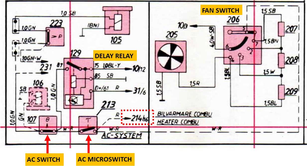 Feel free to contact me if you have questions or if you can help with this info: CONTACT ME |
|
|
|
|
| So then is LATER 240 AC BETTER? If Colder is Better, the answer is probably YES! Certainly possible with some careful work, lots of talent and some good luck.  |
|
|
Early 240 with Thermal Expansion Valve versus later Orifice Tube.
All 240s before 1991 were older THERMAL EXPANSION VALVE (TXV) type systems. Later 240s made from 1991 to 1993 got a more modern
system that can be recognized by the big silver aluminum Accumulator/Drier near the right side
firewall. These later systems were a different
design, which incorporated an
ORIFICE TUBE
rather than a THERMAL EXPANSION VALVE (TXV) found in older
systems.
The 1991+ system using an Orifice Tube still retained R12 refrigerant through 1992. Then the 1993 models were all changed to use the brand new R134a refrigerant. The "How to Design and Build AC" video near the top of this page can also help explain the functional differences in more detail. |
|
|
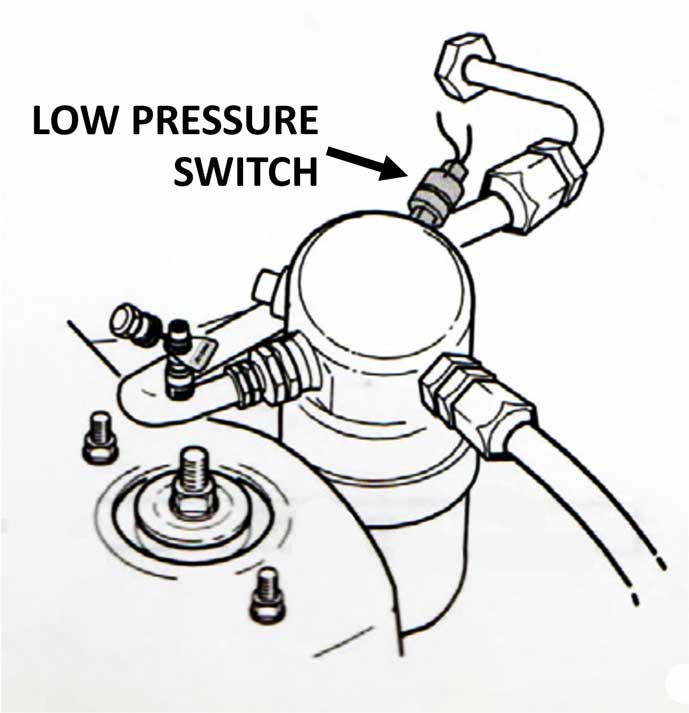
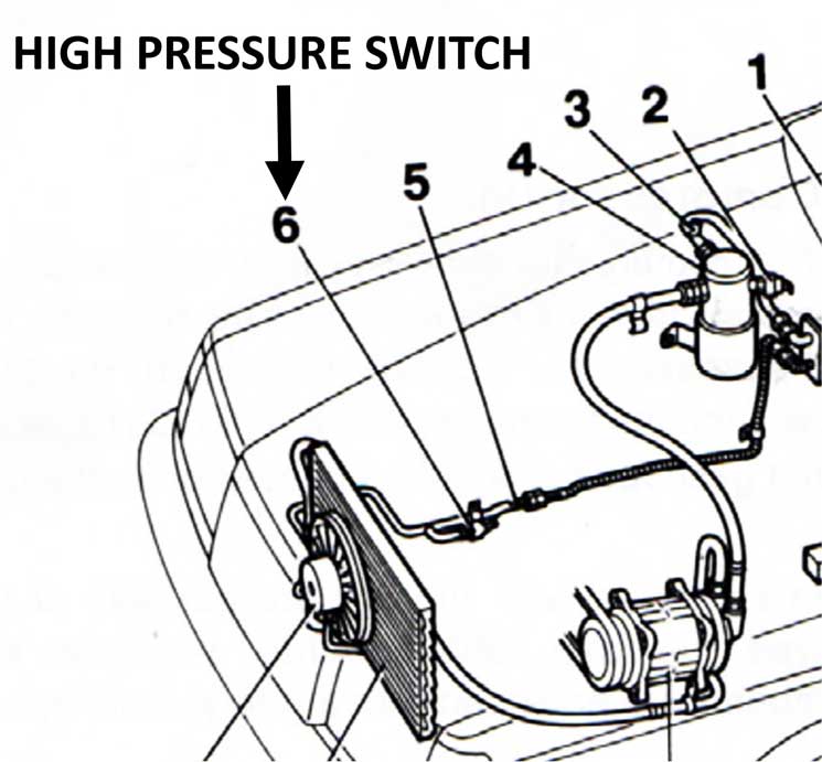
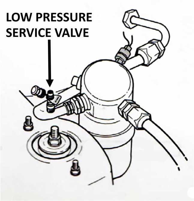
Image below of 1991-93 240 AC (showing larger accumulator/drier near right firewall).
 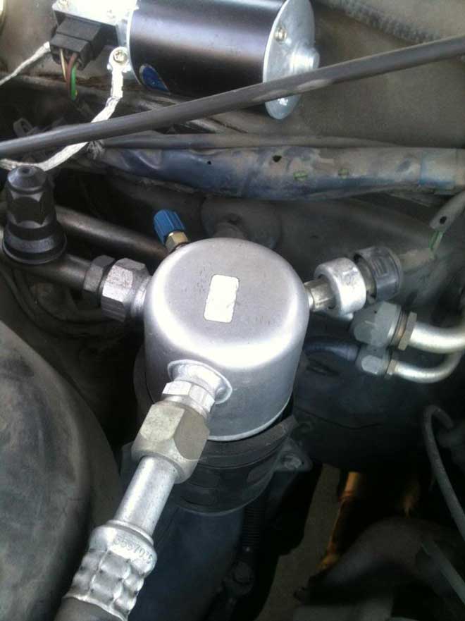 . Late 240 AC Components Here's an overall image of the entire LATER 1991-93 240 AC system along with a later style AC evaporator box, accumulator, compressor and condenser.  AC Switch original location for 1993 240.  . 1985 versus 1993 Evaporator Box Comparison The below image shows a side by side comparison of a 1985 (on left) and 1993 (on right) evaporator box. This view is of the bottom, showing the vacuum reservoir used for vent control functions. The evaporator boxes are slightly different in a few measurements, but ultimately can be interchanged if you're up to the challenge of such deep dash disassembly. 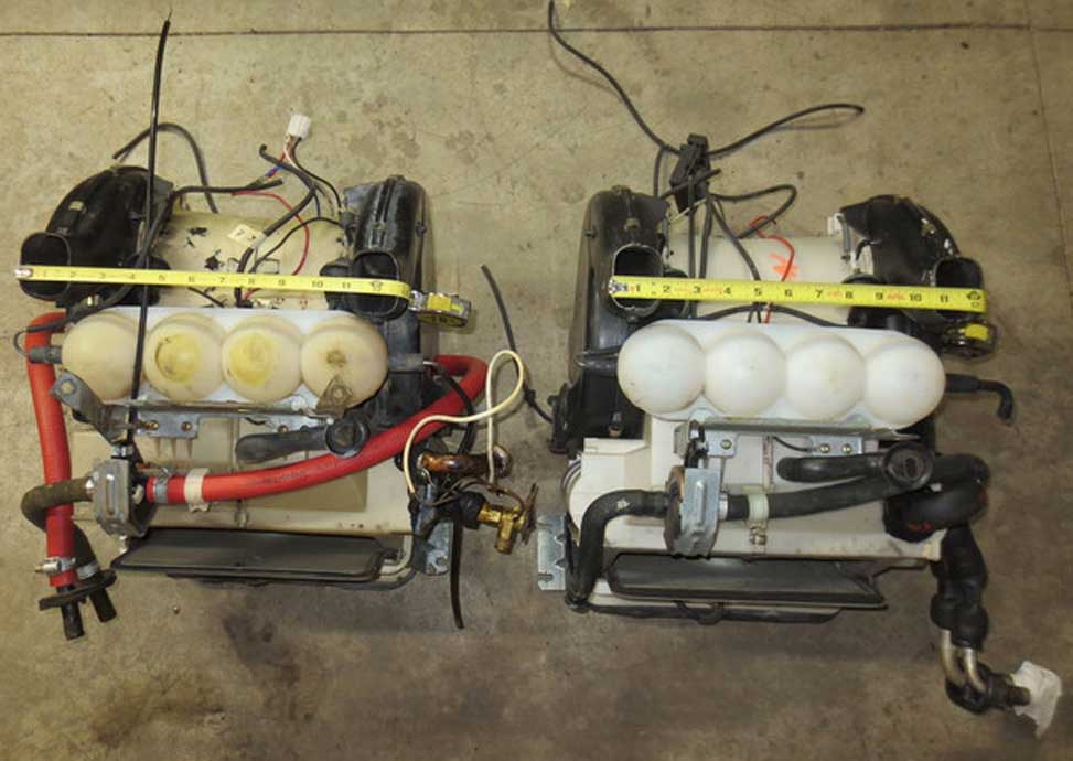 Evaporator Coil Design Changes for 1991 and later. Early Evaporator Coil versus Late Evaporator Coil. The first photo below left shows the old style COPPER TUBE AND FIN design. The second photo below right is a more efficient and larger aluminum PARALLEL FLOW coil design, which was used in 1991-93 240s. 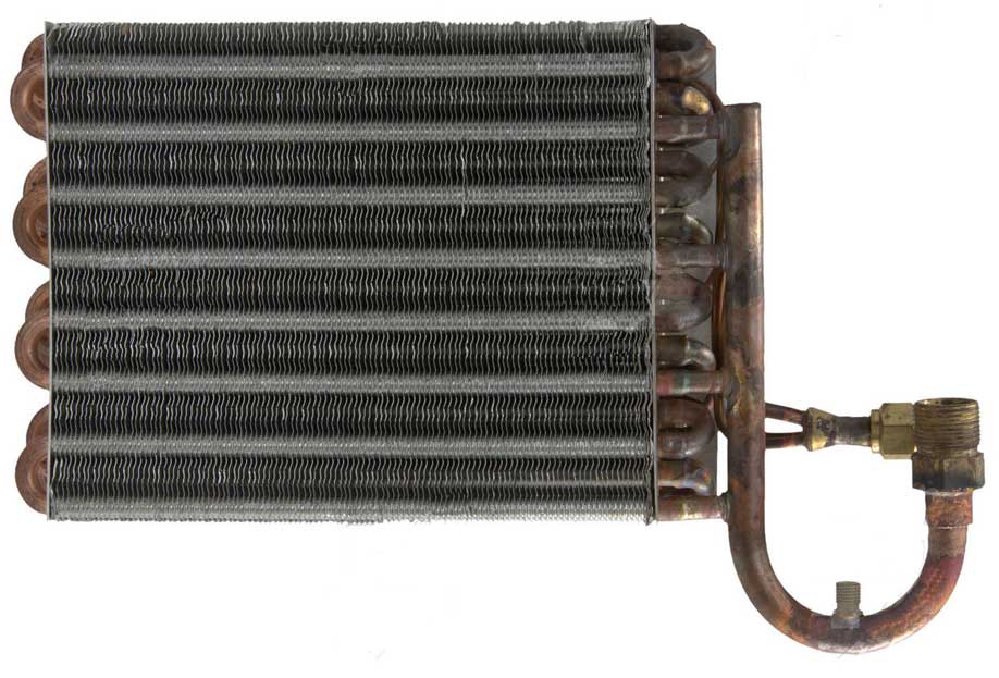  As you can see above the pipe connections are very different. The advantage of the later type is better heat transfer efficiency. If you have an idea to use the later evaporator coil in an early TXV system, that would take some enginuity in re-configuring the pipes to look like the TXV ones. I can't say I know of any such conversions, but it's certainly possible. Standard or Metric Fittings? 240 AC hoses, couplings and fittings have always been standard SAE thread components. All of them are a standard common thread type, except for one year. It has been reported that for 1993 ONLY, the accumulator on the firewall received METRIC THREAD fittings. If look at your AC fittings and see these NOTCHES below, that fitting is METRIC. If no notches, then it's standard. 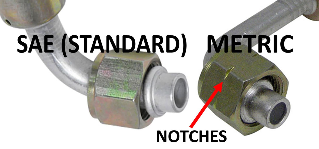 More general information about 240 AC systems can be found in the next section below. FRONT CONDENSER INFO I have some useful info on ORIGINAL versus NEWER style condensers in my CONDENSER SECTION further down in my page. 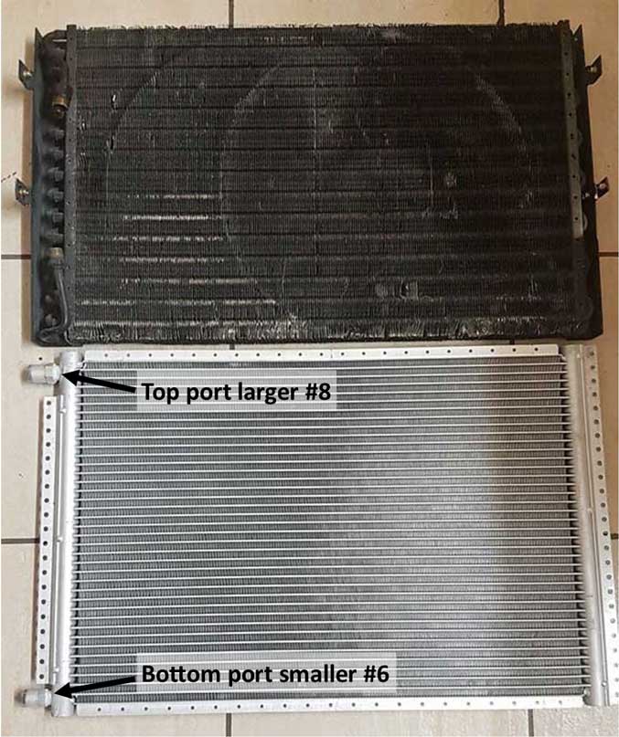 |
|
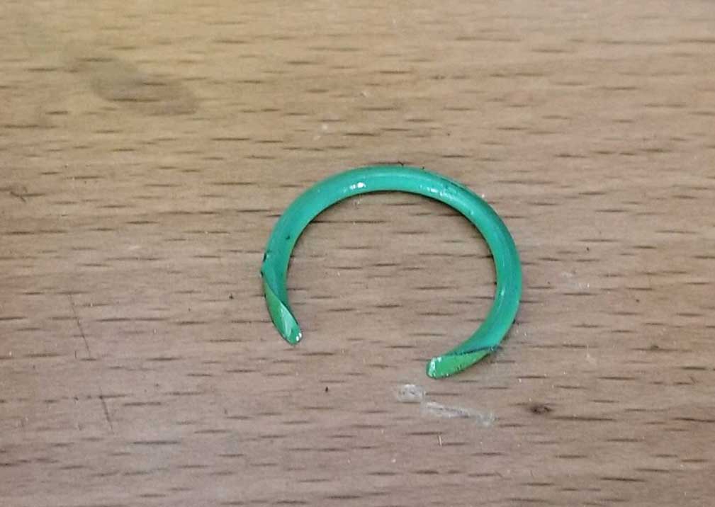
Introduction of the ORIFICE TUBE in the 1991 240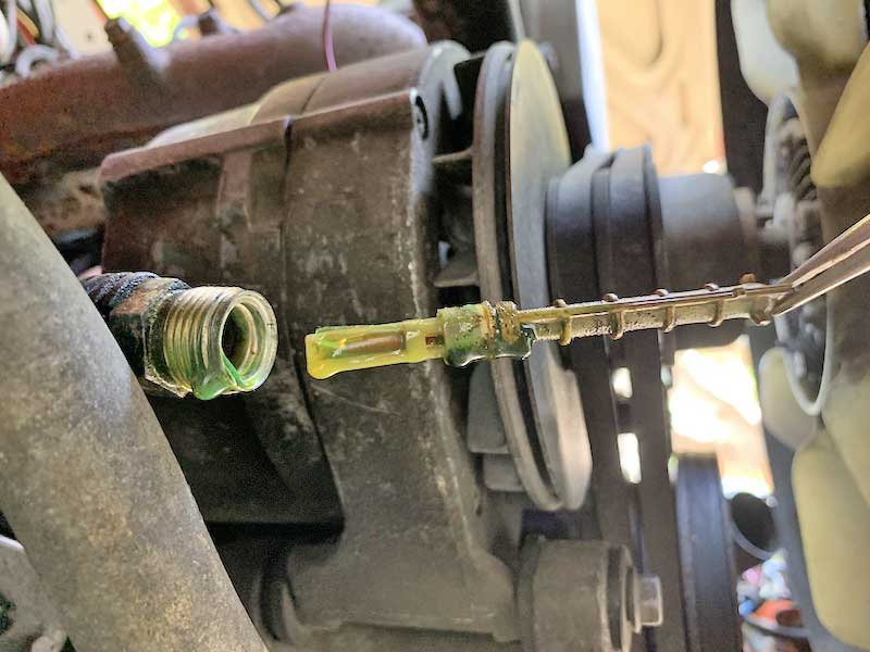 Here's a photo of a 240 ORIFICE TUBE being removed from the high pressure AC pipe. An orifice tube or orifice valve is a restrictive valve which is meant to force the high pressurized refrigerant to expand after it passes the this valve restriction. The expansion of compressed refrigerant creates the super-cooling effect, which is what cools the evaporator coil in the dash. An orifice valve is generally has a chamfered inlet and with a plastic valve body inside the metal tube. It can become clogged or gummed up over time if debris or contaminates get into the system, especially if the system was not in use or left open to elements for a period of time, or in the case of it becoming contaminated by debris from a compressor failure. This valve can easily be removed and replaced if it's questionable. This photo above is from the following thread on Converting an Early 240 to a Later AC System: turbobricks.com/ac-from-a-93-to-a-90.357795/ |
|
| USEFUL 240 AC PART NUMBERS 1363449 Compressor Relay (near AC switch). 1395590, 3513066 Compressor 240 to up 1992 R12. 6841028 Compressor 240 1993 R134a. 1370235 Accumulator/Drier 240 1990 R12 (RHD, LHD). 9144329 (1388667) Accumulator 240 1991-92 R12 (LHD-USA). 3540009 Accumulator 240 1991-92 R12 (RHD). 3540588 Accumulator 240 1993 R134a (RHD). 9131972 Accumulator 240 1993 R134a (LHD-USA). 3537866 Low Pressure Switch (pressostat) 1991-92 240 R12. 3537506 Low Pressure Switch (pressostat) 1993 240 R134a. 3522250 Thermal Expansion Valve (TXV) 240 1990. 1324829 Orifice Tube Insert 240 1991-92 R12. 3545086 Orifice Tube Insert 240 1993 R134a. 1214851 Evaporator Coil 240 to 1990 R12 (RHD, LHD). 3540231 Evaporator Coil 240 1991-93 R12 or R134a (LHD). 3522858 Evaporator Coil 240 1991-93 R12 or R134a (RHD). 1259556 Condenser before 1991. 3540373 Condenser 1992 R12. 3540647 Condenser 1993 R134a. 3540227 Condenser Fan Pressure Sensor/Switch 1991 R12. 6848106 Condenser Fan Pressure Sensor/Switch 1992 R12. 3540657 Condenser Fan Pressure Sensor/Switch 1993 R134a. 1323592 Condenser Fan Relay |
|
|
|
|
| Can I convert my old 240 to have later, more modern AC? Yes you can. For those of you looking to convert a 1990 or earlier 240 to use 1991 or later AC components, here are some useful discussion threads on this topic: turbobricks.com/index.php?threads/what-a-c-components-to-pull-from-a-93.322912/ turbobricks.com/index.php?threads/are-the-91-92-heater-ac-units-superior-to-previous.330298/ turbobricks.com/index.php?threads/a-c-restoration-and-conversion-to-r134a-in-pre-1991-240.355505/ turbobricks.com/ac-from-a-93-to-a-90.357795/ CLICK HERE to see a comprehensive WIRING DIAGRAM for later 240 AC BELOW. |
| 240 AC Systems. General System Overview Information. If you want to learn more about 240 AC systems, then this information will help. |
The ONE exception is the 1993 (one year only) 240, which reportedly used an accumulator/drier with metric threaded fittings. If look at your AC fittings and see these NOTCHES below, that fitting is METRIC. If no notches, then it's standard.
|
|||||||
|
|||||||
|
|
|||||||
|
|||||||
|
|
|||||||
|
|||||||
|
|
|||||||
| 240 Vent Control Diagram for Vacuum Lines 1981-93 240 (USA). I created the below diagram because nothing like it exists anywhere in any Volvo Greenbook and many people needed to know where all those vacuum hoses in your dash go. For more vacuum diagrams, go to my Vacuum Diagram Page 
|
|||||||
|
|
|||||||
|
|||||||
|
|||||||
LATER WIRING DIAGRAMS Here's a comprehensive wiring diagram I made for the 1991-93 240 AC system. The four fuse holder on the top left is present only on a late 1993 240. CLICK the BELOW IMAGE for a larger photo. |
|||||||
 |
|||||||
| Later AC Pressure Switch Mods Here are TWO Alternate MODIFICATIONS below of the low pressure switch and high pressure switch condenser fan circuits for a LATER 240. 1. LOW PRESSURE SWITCH MOD: This mod shown in the below image eliminates the Low Pressure Switch in the Accumulator/Drier. This mod is normally NOT TO BE DONE unless you know a good reason to do it. Otherwise you can just ignore this mod. This low pressure switch is there to switch OFF the compressor circuit when pressure drops below a certain level. This is designed to help regulate the cold evaporator temperatures. Eliminating this switch could allow the evaporator temperature to drop too low (which might be a reason to use it if you know what you're doing). If you're not sure, then you should ignore this mod. The next mod can still safely be done for the condenser fan. 2. CONDENSER FAN HIGH PRESSURE SWITCH MOD: Normally the condenser fan only comes on when both Pressure Sensors are closed. I thought an alternate idea might be useful with regard to eliminating this High Pressure Sensor. This modification is the lower half of the below diagram. TWO wires from the condenser fan relay are changed (see the blue boxes below). This mod allows the condenser fan to continuously run anytime the AC Compressor circuit is activated (anytime the compressor is running). You can compare this to the factory diagram arrangement above and decide for yourself if this is appropriate. 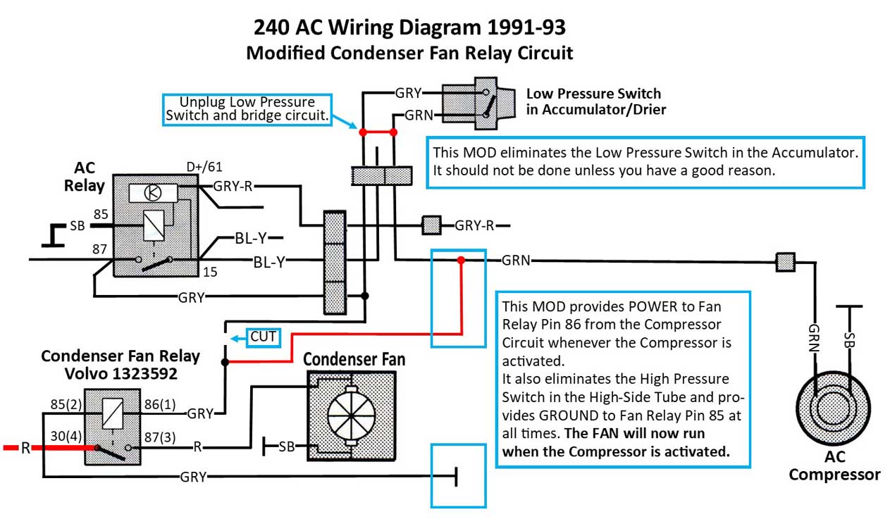 |
|||||||
AC Relay PN 1363449. Located near AC switch in dash.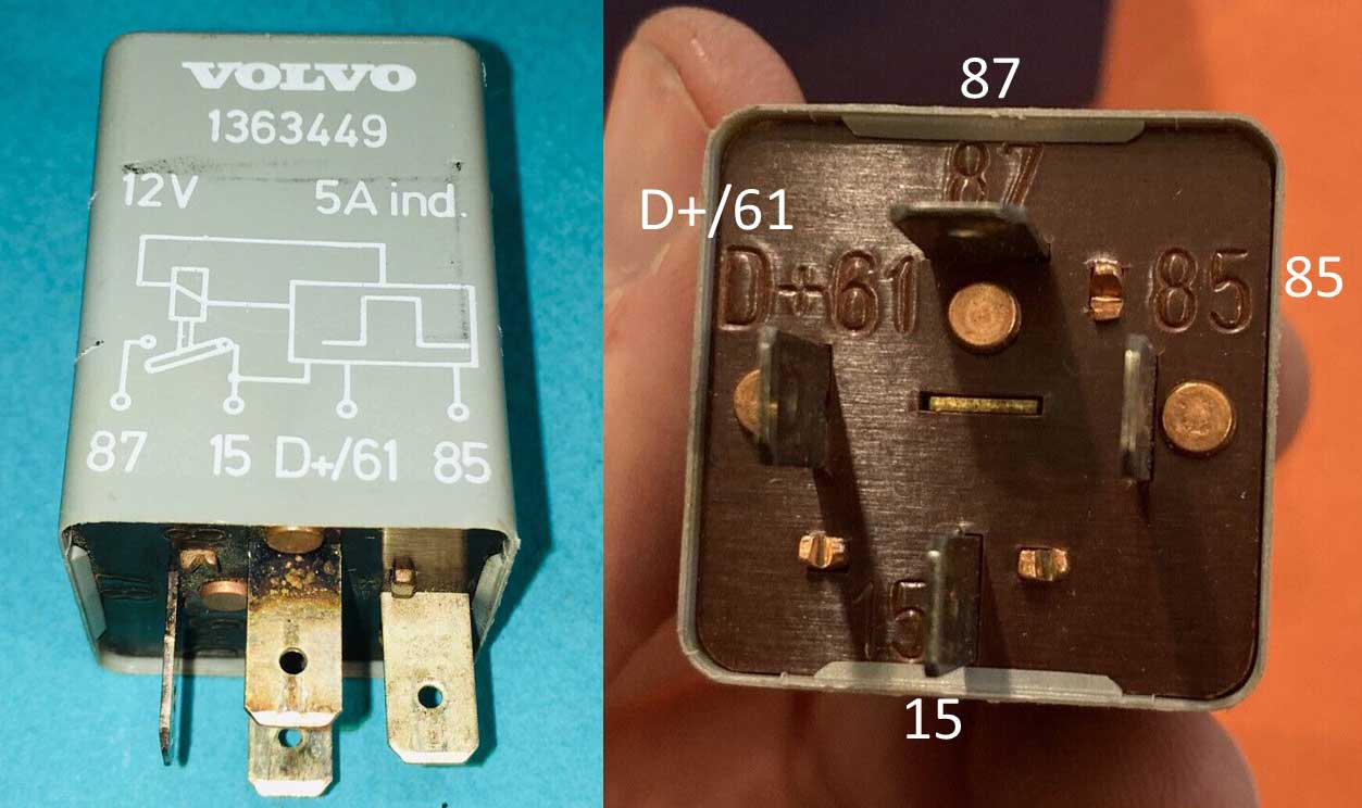 Condenser Fan Relay PN 1323592. Located under hood on left inner fender between battery and suspension tower. 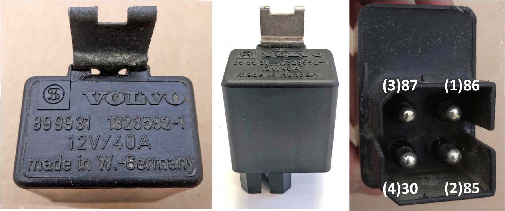 |
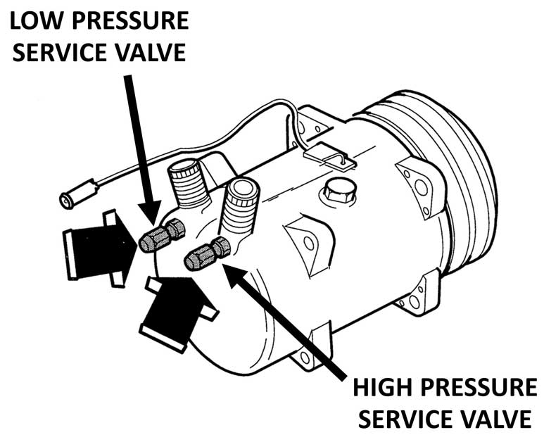
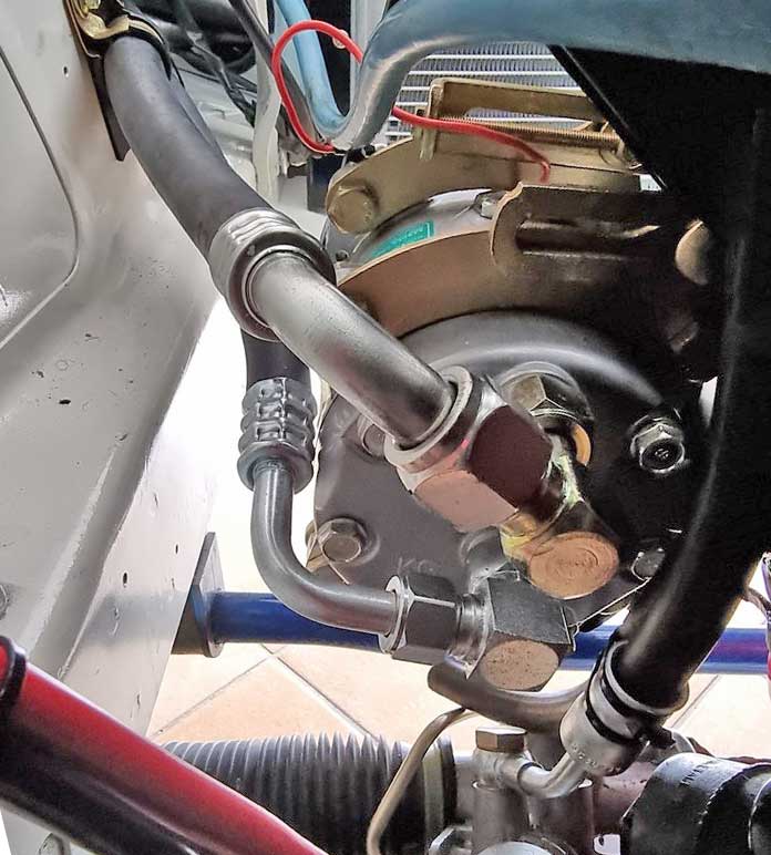
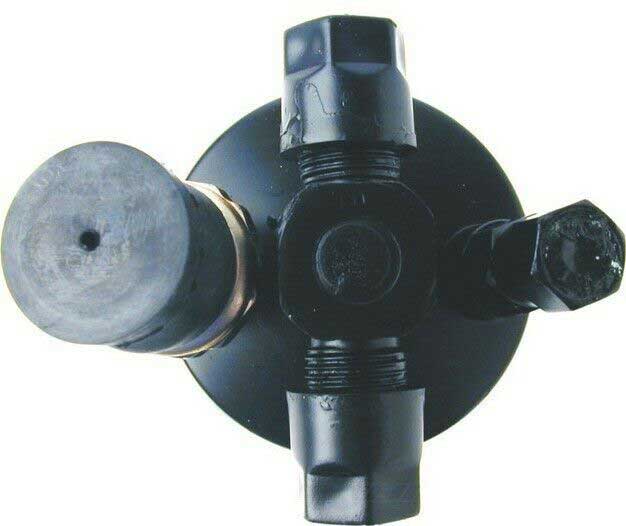
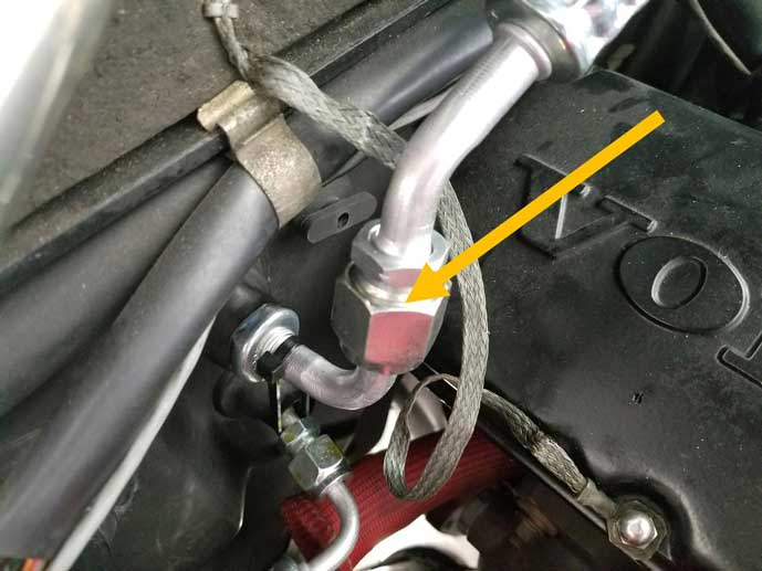
As previously mentioned, R12 was eventually banned in the U.S. and other developed countries in 1996 and then worldwide in 2010. R12 is dichlorodifluoromethane, a colorless gas sold under the brand name Freon, Freon-12 or R12. It's classified as a chlorofluorocarbon (CFC). This CFC part is why it was banned because it has been reported to potentially damage the Ozone layer.. Thermal Expansion Valves were used in all 240 R12 systems up through 1990. It is commonly believed that thermal expansion valves (TXVs) used in these cars were specifically adjusted by the factory (or by the TXV manufacturer) for use with R12. Then later when one of these 240s got retro-fitted with R134a, it would get a replacement valve that was supposedly calibrated for R134a. This raises questions about us DIY mechanics doing their own AC adjustments. Can we adjust a TVXs to suit R12, R134a or another suitable refrigerant??? If so, what are the parameters? The answer has never been found. 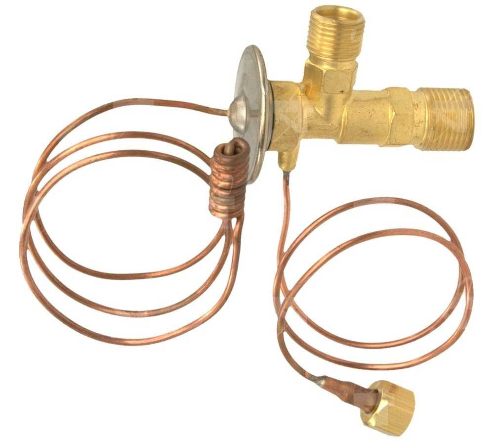 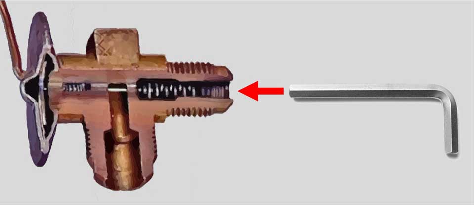 This adjustment method on a TXV used in a Volvo is illustrated above. With the TXV inlet port disconnected, an Allen (socket) wrench is inserted into the inlet port. There's a socket set screw with a spring behind it. That screw is is turned to adjust. There are many opinions on what these adjustments need to be for different refrigerants and so far NONE of it is definitive. A discussion thread on setting these valves is posted below. Some people claim to know the answers about this stuff, but I'm convinced no one knows SHIT. TXV Adjusting thread: turbobricks.com/index.php?threads/how-to-adjust-an-expansion-valve.213526/ USING PROPANE AS A REFRIGERANT. |
|||
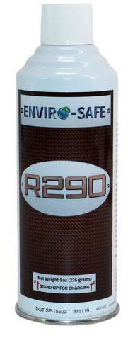
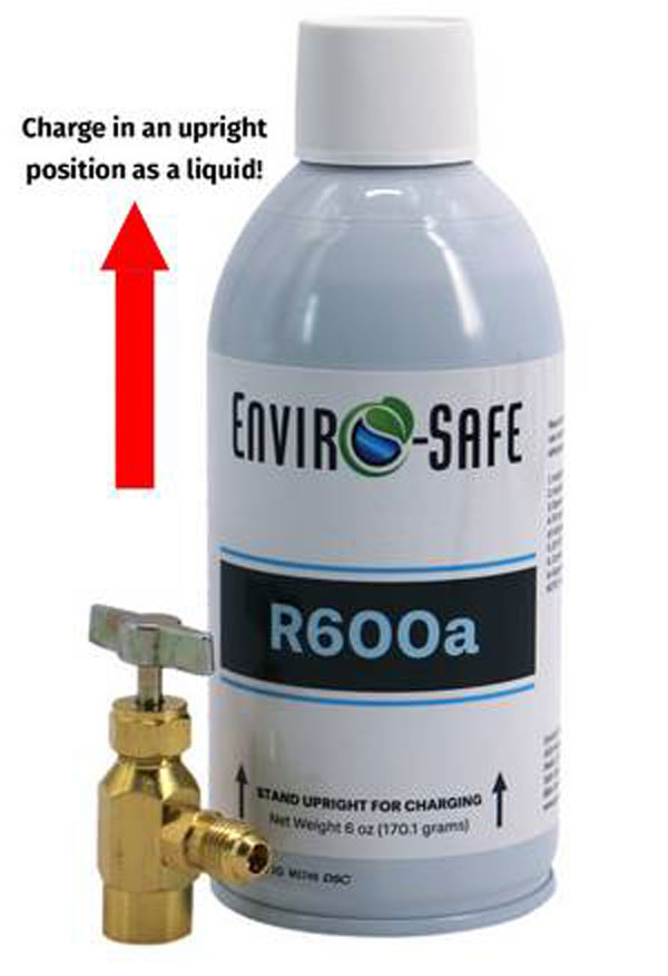
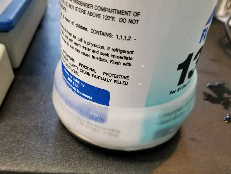
Using R152a (Canned Aerosol Compressed Air AKA: Dust Off) R-152a (1,1-Difluoroethane) is a hydrofluorocarbon (HFC) is used as an aerosol propellant for canned dusters. It reportedly has thermodynamic properties similar to R-134a. I don’t have experience with it and I don’t have enough info to offer a recommendation, although I haven’t aggressively researched it. There are lots of discussions and videos, and experimentation is fine, but I have questions. How much R152a is in a duster can? What else is in a duster can? Air? Any water? You can buy R152a made for refrigeration and it'll be pure, but more money. If R152a is thermodynamically similar to R-134a, how much should be used in an R134a system? I have a chart in this page that'll compare/convert R12 and R134a to Duracool. Is there a chart somewhere showing how much R152a to use? I know from experience that a precise charge is very important with Duracool or R290/R600a charging. When charging with only 10 or 11 ounces total, being over or under by an ounce can make a big difference. From the net: A duster can containing R152a (1,1-Difluoroethane) is reportedly almost entirely pure propellant, but it often contains an specific additive and potentially trace impurities: Bitterant (Denatonium Benzoate): Most consumer dusters include an intensely bitter flavoring agent like Bitrex. This is added by manufacturers to deter intentional inhalant abuse (huffing). Trace Contaminants: Because it's packaged for cleaning electronics rather than refrigerant use, it may contain moisture, machine oils, or other residual hydrocarbons. If it has moisture in it, I strongly recommend using a new accumulator/dryer for each new charge. That can be expensive if you’re experimenting. DURACOOL (Hydro-Carbon Refrigerant MIX) In 2012 I gave up on using straight propane and I began trying Duracool 12a replacement http://www.duracool.com/. I later learned that Duracool is a mixture of Propane (R290) and Butane (R600a). The precise mixture is not known by me and it's kept secret by Duracool. The addition of Butane in the mix seems to be a key in making this mix more consistent than propane alone. My introduction to Duracool was many years before I installed Classic Air AC and I spent a lot of experimental time trying to get the original AC dialed in. I tried a number of different thermal 240 expansion valves and a LARGE number of different expansion valve settings. My 240 eventually got pretty good cooling on the highway for a while, but then I found intermittent problems at idle (although it seemed to get a little better with Duracool rather than with just propane). I kept experimenting over the years and I wasted a lot of money on different expansion valves and a huge variety of TXV settings, hoping to find the right combination that worked. Things never got great and ultimately I remained less than satisfied with my AC. So when I heard about the possibility of using Classic Auto Air, I paid attention. CLICK HERE TO SEE MORE ABOUT PRESENT DAY DURACOOL PERFORMANCE AND MY ULTIMATE RESULTS WITH CLASSIC AUTO AIR. IMPORTANT NOTE FOR 2023: In 2023 it appeared the availability of hydrocarbon SUBSTITUTE refrigerants in the USA was being threatened by the US EPA. I think this has probably relaxed now (2026), but this is something to be aware of. In 2023 I began noticing that some R12 substitute companies, such as Enviro-Safe, had REMOVED all hydrocarbon (HC) R12 substitutes from their web pages. Some pages mentioned this was the result of new US EPA SNAP regulations that became effective in May 2023. I didn't notice any restrictions in sales in the Duracool page. Here's the EPA bulletin: https://www.epa.gov/snap/unacceptable-substitute-refrigerants Here's more about what is considered an R12 substitute (HC-12a): HC-12a Wikipedia So if alternate refrigerants become hard to get or unavailable, what can YOU do as an amateur DIY AC tech? You can do plenty. I've already begun some experiments of my own with mixing Butane and Propane. You'll see some info below of blending the two. I think a 50/50 mix of the too is a good place to begin. When I began trying this, I noticed that when beginning with a charge of Butane only, I noticed it would cool, but the reduction in temperature was slow. Then as I began adding Propane, that reduction in temperature sped up rapidly. So increasing the percentage of Propane to Butane made it COLDER. It's important to plan ahead so in the end you don't overcharge your system. If you goof and add too much, you need to start over. A good chart to use to understand how much TOTAL WEIGHT of refrigerant mix to use is in the Duracool chart HERE. For example, my custom system is designed for 24 ounces of R134a. The Duracool chart shows the equivalent for my car is only about 9 to 10 ounces total of Duracool or Propane/Butane mix. So if you try a Propane/Butane mix, try not to exceed the total amount for your car. A 1986 240, which uses about 2.9 lbs of R12, should only need about 16 ounces by weight of Duracool or Propane/Butane blend. A 1993 240, which uses about 1.63 lbs of R134, should only need about 11 ounces by weight of Duracool or Propane/Butane blend.  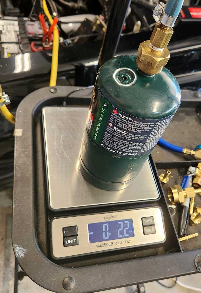 I use a digital postal scale to monitor the weight of a canister as the refrigerant is being charged into the system, so I can see ounce by ounce precisely how much is going in.. amazon.com/Weighmax-Durable-Stainless-Digital AUTOMOTIVE FUEL PROPANE: Keep this in mind. I've read some opinions that say some Propane available for AUTOMOTIVE FUEL may already have a percentage of Butane already in it. I don't know how you can test for or avoid this unless the source can tell you the content. The prevailing opinion for a typical 1 lb. propane fuel canister you find at a store is that those are usually fairly pure Propane, but maybe not the purest you can get. Who knows? Reportedly the purest you can get is that which is classified as R290 refrigerant. The ultimate goal for cold AC is to get an evaporator temperature as cold as possible, but to stay above the temperature where a freeze-up can happen. Staying above 32°F (0°C) may be a good goal to avoid freeze-ups. If you cannot find a way to measure your evaporator temperature, then measuring vent temperature will be the next best thing. But read here for how I measure and regulate my evaporator temperature. Charging an auto AC system yourself and mixing two different chemicals is not difficult if you can use an AC charge hose and a postal scale. INVERTED OR NOT? 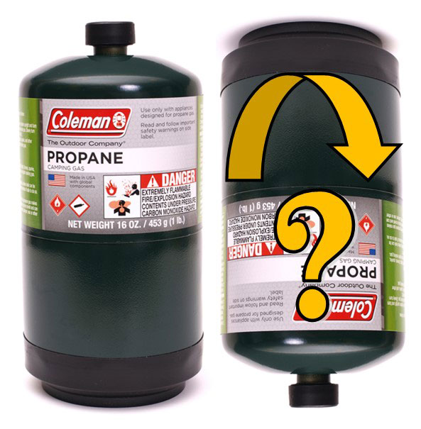 If you search for information, you'll find a lot of opinions. Some will tell you that you must INVERT a Propane can when charging or the AC won't cool. I think this is B.S. If you're installing only ONE chemical at a time, I think the can should be upright (installed as a GAS). Inverting a can and charging as a LIQUID instead of gas is generally recommended for REFRIGERANT MIXES, such as Duracool (which is a mix of Propane and Butane), or any refrigerant which is made up of two or more chemicals. This is so the mix stays in MIXED FORM as it's installed. The concern with mixed refrigerants is that if you install it UPRIGHT as a GAS the mix might be uneven. The lightest gas might evacuate first. Propane is a single component chemical and not a mix. It's made of hydrogen and carbon molecules and those will not separate into just hydrogen or just carbon on their own. So installing Propane or Butane separately UPRIGHT as a gas is ok. |

https://www.youtube.com/watch?v=kU68Z3qCD18 |
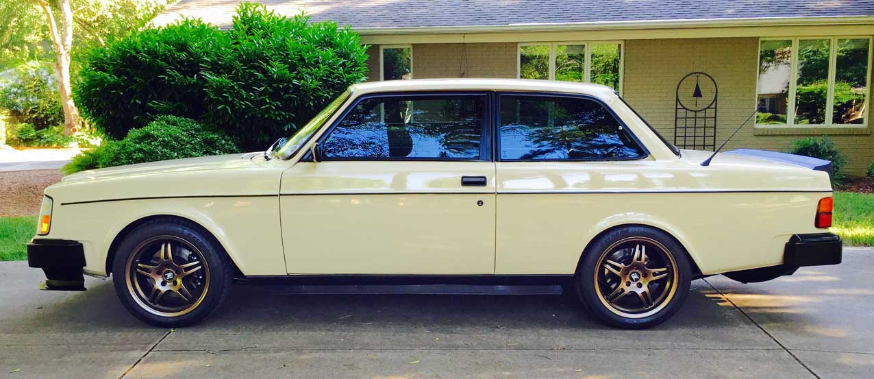
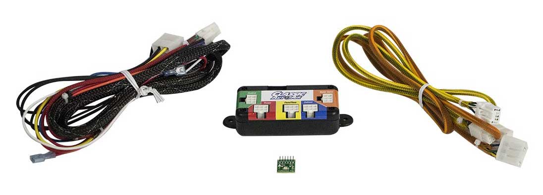
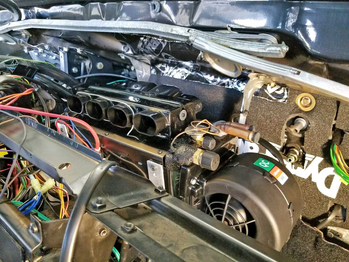
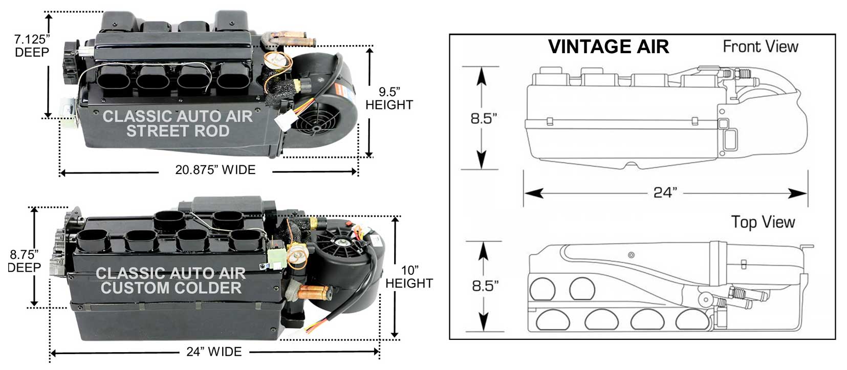
The answers I got from hot rod owners about their Classic Auto Air or Vintage Air systems were surprisingly very positive. So then in 2016, after Michael Yount told me he had successfully installed a new Classic Auto Air system in his 240 (below), I paid attention and started seriously re-considering an aftermarket system. |
CLASSIC AUTO
AIR installed in a 240.
|
|

|

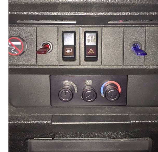
In their place is a new electronic control panel with knobs. It has fan speed, vent selection (front vents, upper defrost, and lower heat) and a cold/warm temp knob. Try not to be confused when you browse Classic Auto Air's web pages. They also show setups using some CABLE controls, but they don't explain very well why they show both setups. Basically the cable controls they offer are designed for classic cars where the owner wants to retain the original look of vintage cable controls. |
| Before completing my new AC system installation, I first gutted the interior and installed DYNAMAT. CLICK HERE for the 240 DYNAMAT Installation Page
|
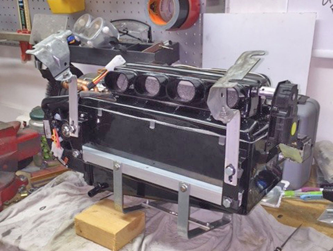
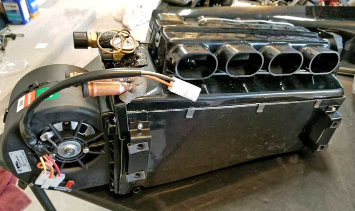
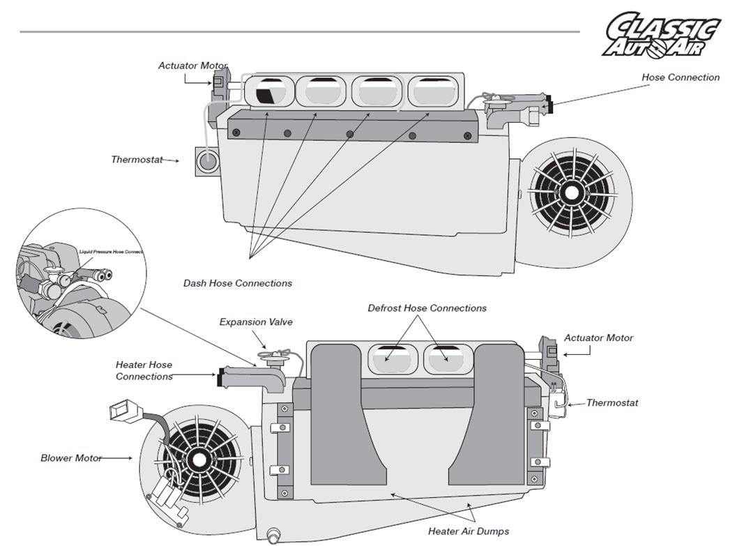
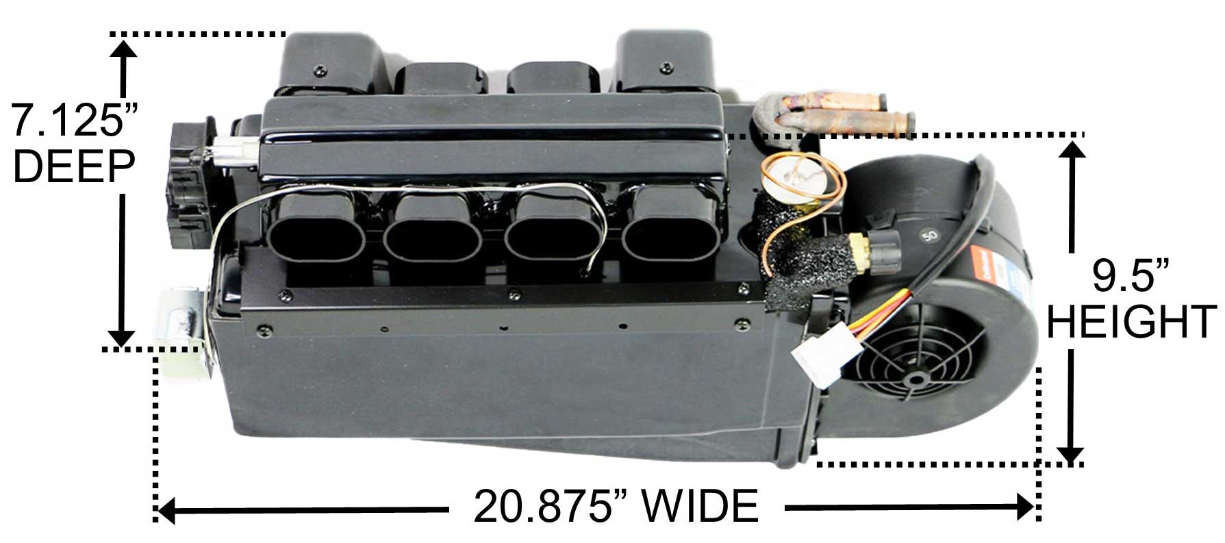
Classic Auto Air Installation in my 240
|
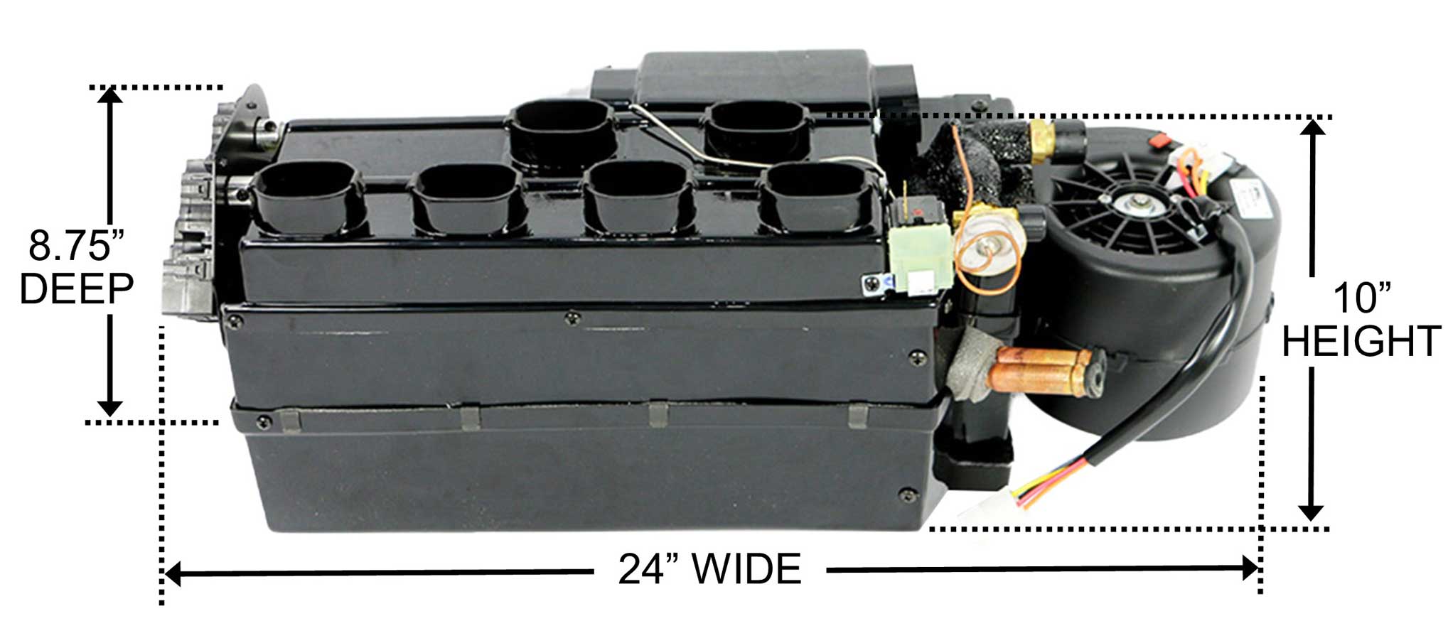
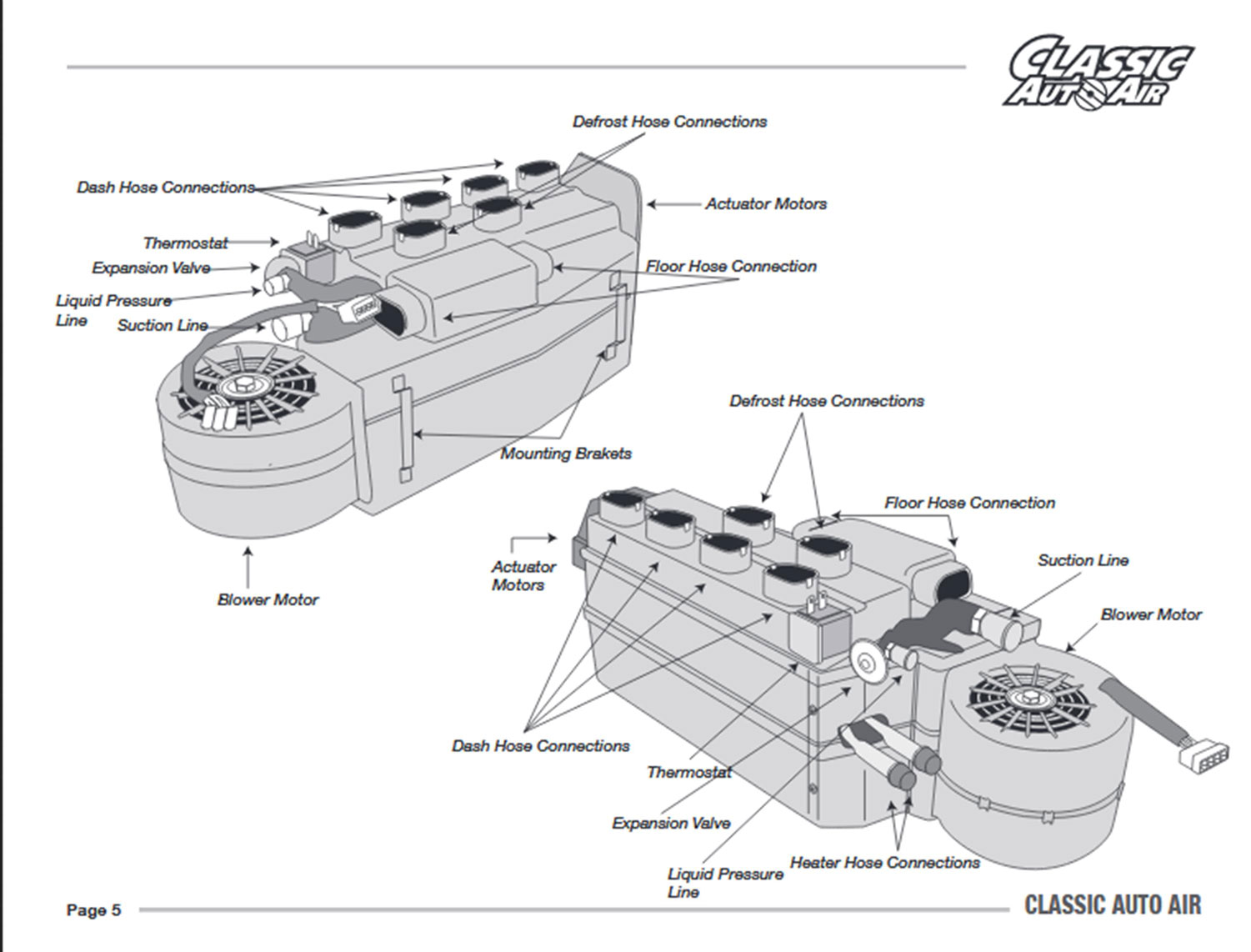
I 2017 there were not many
photos of this unit in the Classic Auto Air site, so I have
included some here.
       |

|


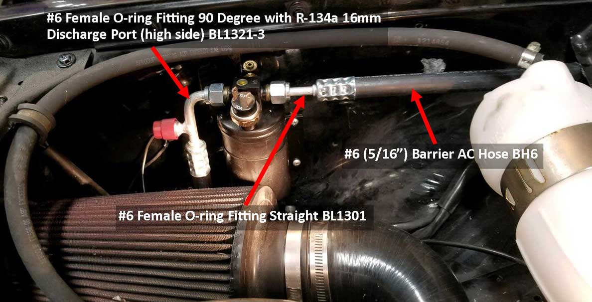
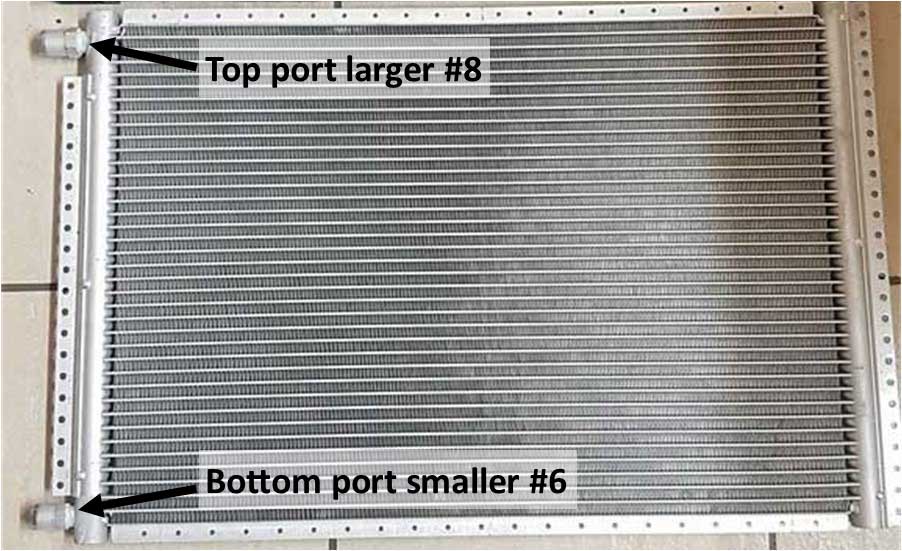
The above photo is from Aris (from Greece) taken during his 240 build, which can be found in his thread here: forums.turbobricks.com/310632. The above photo shows the original black 1985 240 condenser, which is made from TUBE and FIN construction. All 240s up through 1990 received a black condenser similar to this one. The original size was about 15.5 x 26 inches. Aris then fitted a new 16 x 24 inch universal PARALLEL FLOW CONDENSER, also shown above. TAKE NOTE that the hose fitting sizes for IN versus OUT on a condenser are not the same size. The top one is larger (#8 male) and is connected to the hose going to the compressor. The bottom fitting is smaller (#6 male) and is connected to the hose to the drier canister on the right fender. I have more info about AC hose sizes further down in my AC build or CLICK HERE. If you're wondering what a PARALLEL FLOW CONDENSER is, it's basically a newer and better design than the original tube and fin style condensers. A parallel flow type is reported to be about 30% more efficient. You can buy one from Classic Auto Air or Coldhose (where I bought mine) or a variety of other places if you search for: Universal AC Condenser. A universal condenser will be available in different sizes, but one in the approximate size of about 16 x 24 inches like the above one will fit OK in any 240 (or see below for the larger 16 x 26 inch condenser I installed).
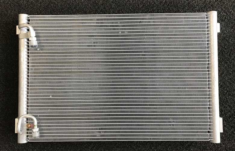    If, by chance, you have a 1991-93 240, you should hopefully already have a superior parallel flow condenser, like this 1991-93 240 condenser shown above. This one above is unpainted, but typically the factory condensers were BLACK. If you have the older tube and fin style (below), you can install a later one like this above with a bit of work, or you can buy a universal type that may or may not fit without a lot of work. The design difference is pretty easy to see compared to this early style condenser below, which came out of a 1990 240. 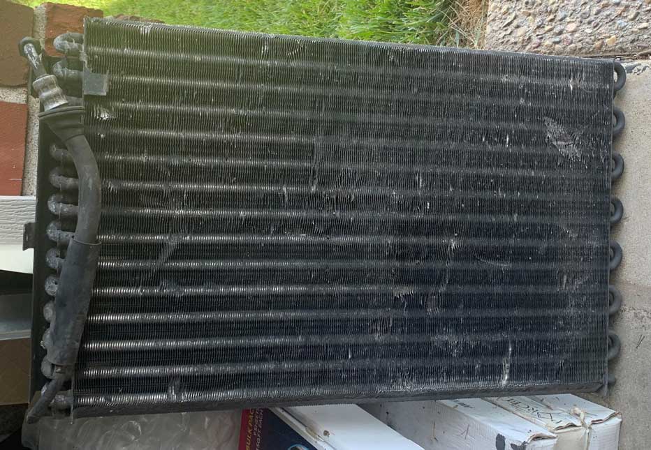 I know you'll want to know this: A straight swap may not be always be possible. The locations or positions of factory AC hoses may not be quite the same between the two styles in a 240. The Volvo factory was not always consistent. Plus if you compare this condenser to the 1985 condenser further up above, you'll see the hose connections have changed over the years. So please understand you may need to change or create some hoses. If creating hoses is needed, you can read more about creating AC hoses further down or CLICK HERE. CONDENSER FANS 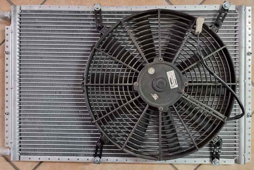 As shown ABOVE, Aris mounted a 16 inch low-profile Spal PUSHER fan on the front of his universal condenser. Spal fans are an excellent choice and are very well made and very powerful. A good pusher fan is recommended to get better air flow when you're stopped or at low speeds. |
|
| Here's a photo below of my universal condenser in my 240. The size I chose was 16 x 26 inches, which I bought from Coldhose. A single pusher fan would be fine, but in my horrible endless obsession for colder AC, I installed dual 11 inch pusher fans, which I mounted to my condenser. 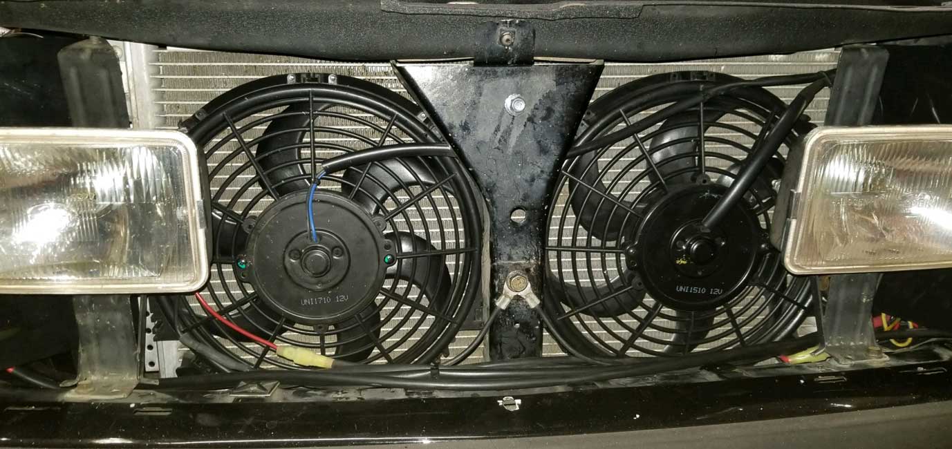 If you're wondering why my horns are missing, I tossed them and then mounted some more serious horns under the car. I have a HORN PROJECT PAGE for that. |
|
|


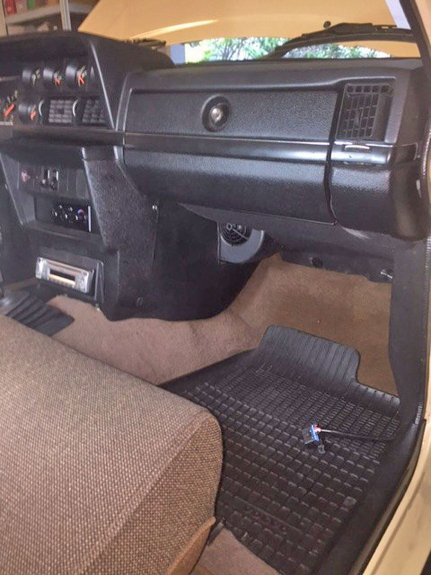
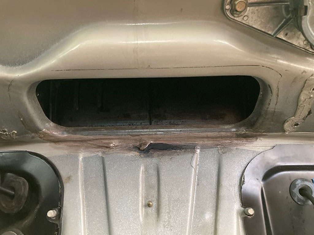
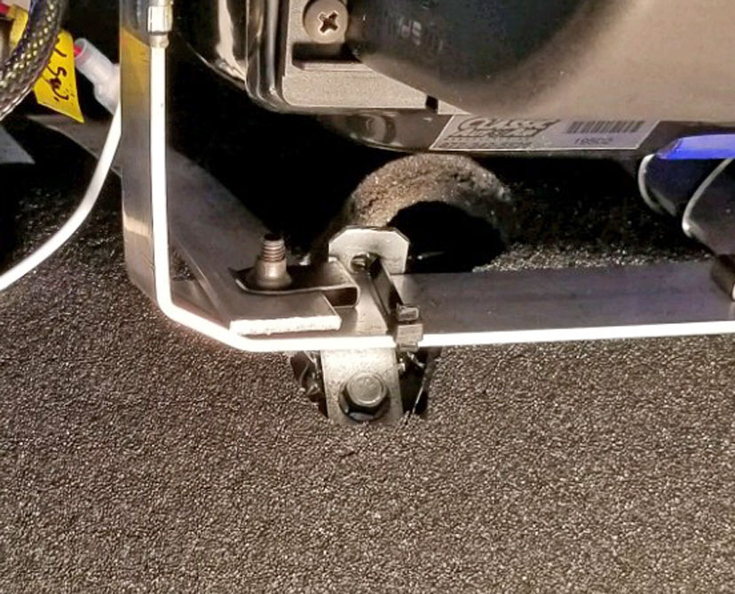
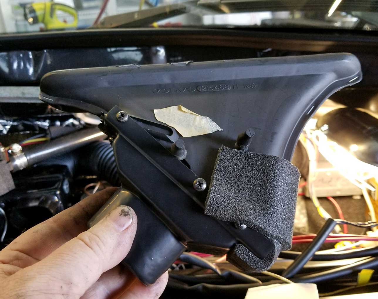
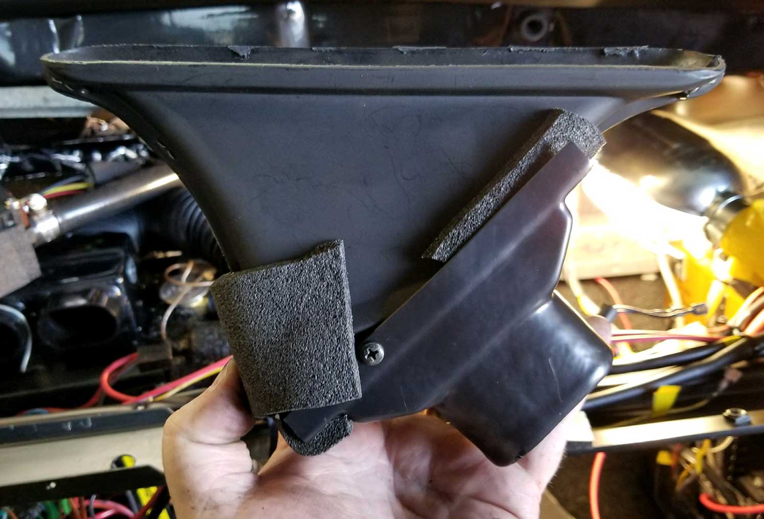
| COWL VENT |
|
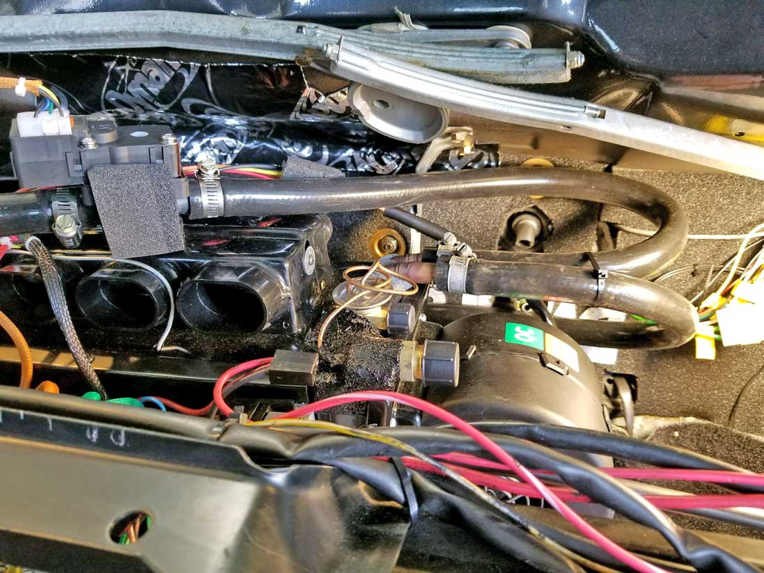
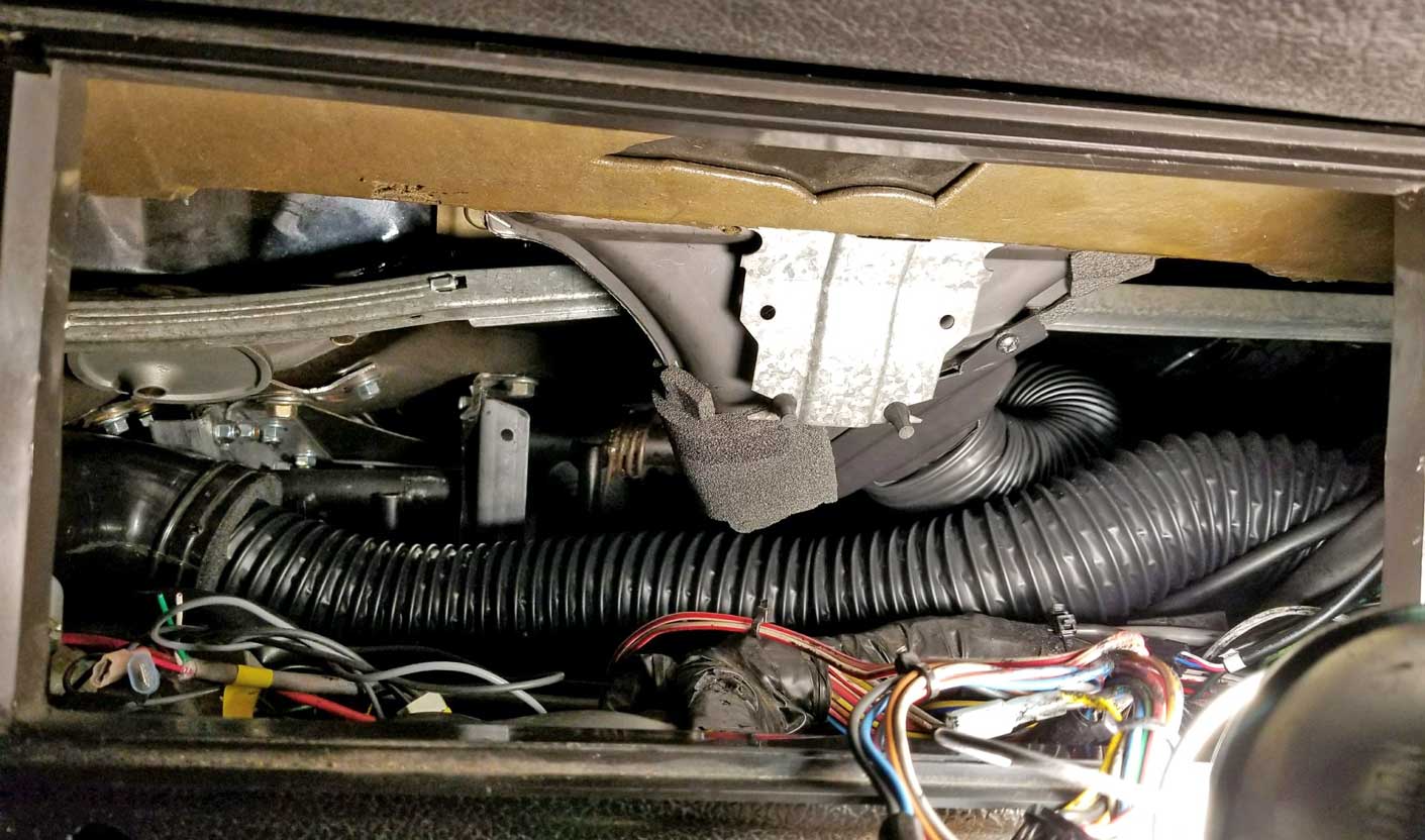
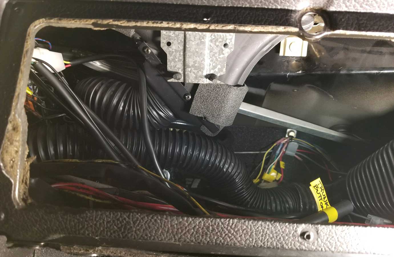
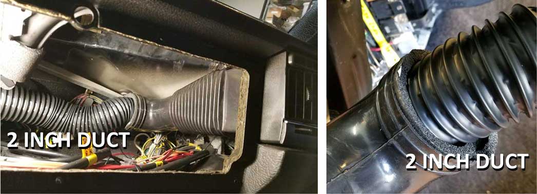
The below photos show a view of the underside of the cowl (looking up) just below
the center of the windshield. This is where the fresh air
cowl vent was located just above the original AC box.
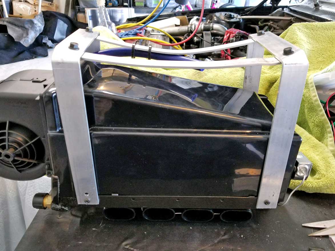
I began by cutting a rigid piece of plastic to the precise shape of the hole. It helped to make this piece out of cardboard first. Then after I had the cardboard size just right, I transfer the shape to the plastic (or you can use metal or whatever material you decide to use). Then I applied a generous bead of 3M black Super Weatherstrip Adhesive around the edge and installed it. Then I further sealed the opening with some Dynamat. Those two brackets in this photo are the original sheet metal brackets which used to hold the top of the original heater/AC box. As Michael did, I used those brackets as top mounts to help secure the new Classic Auto Air box. |
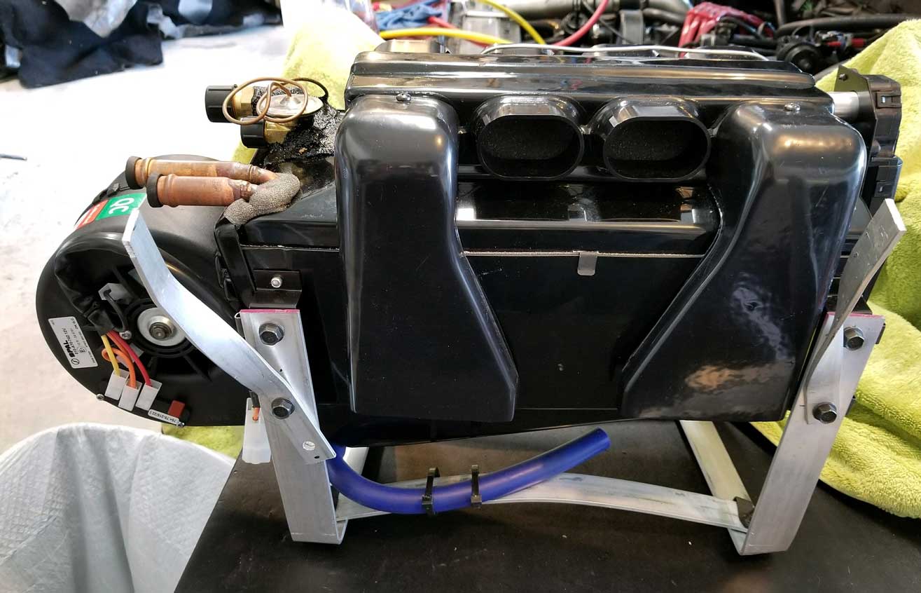
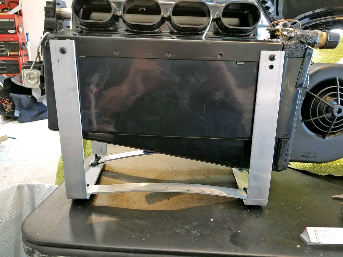
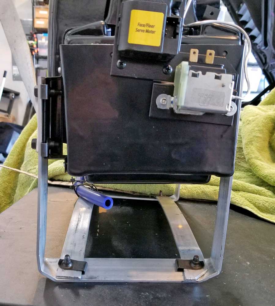
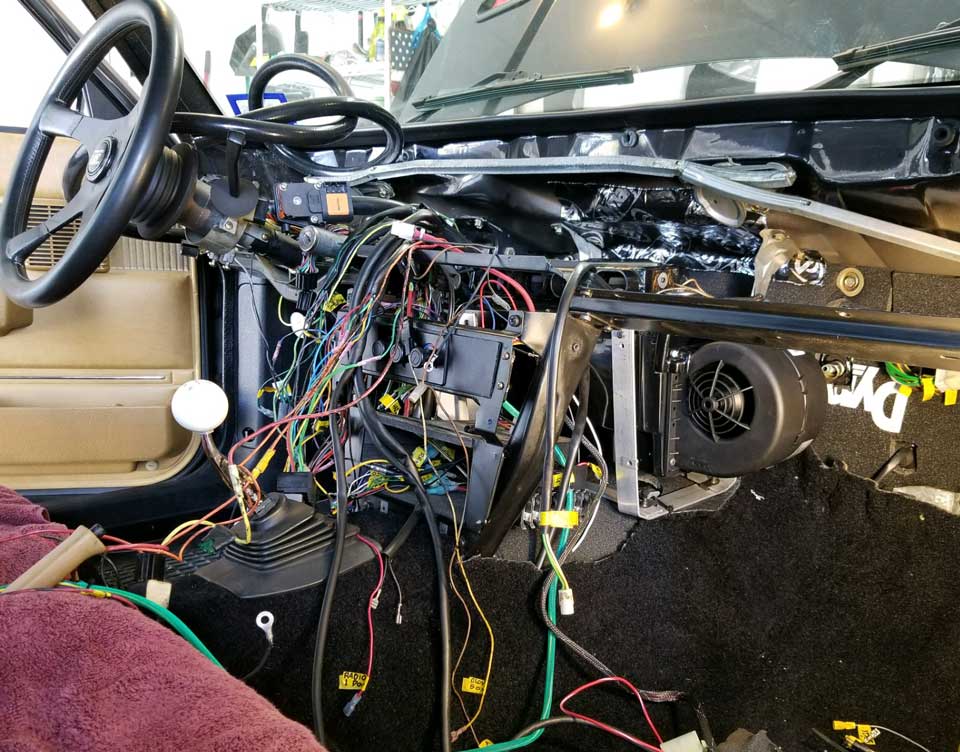
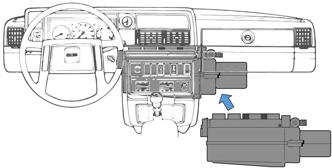
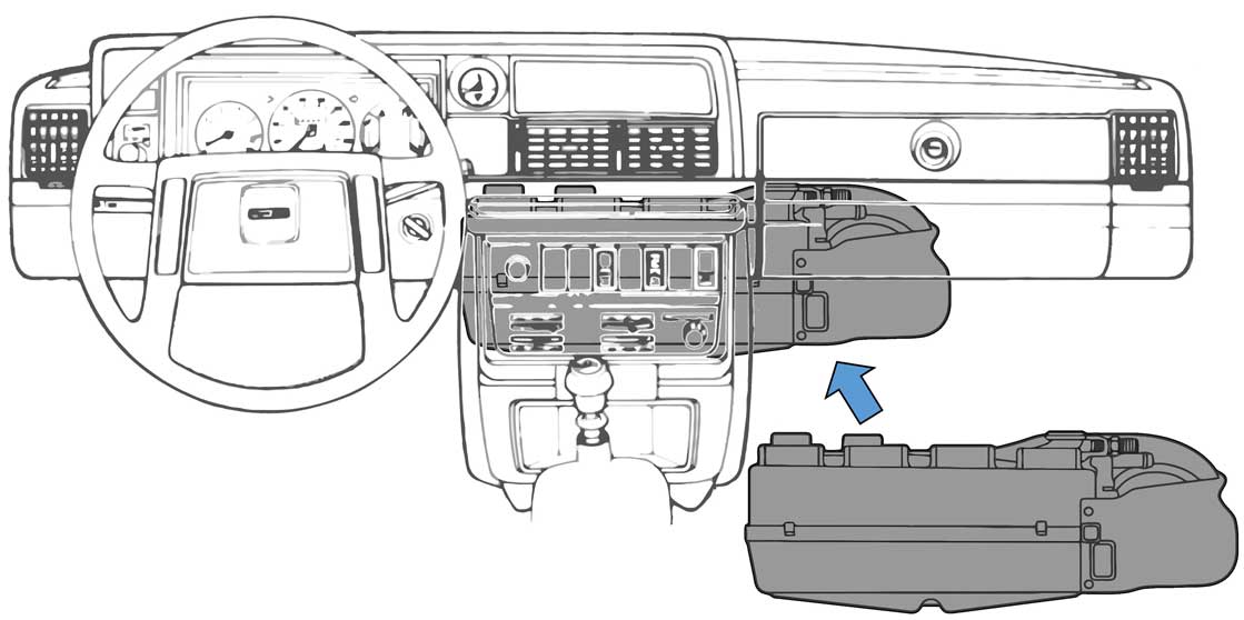
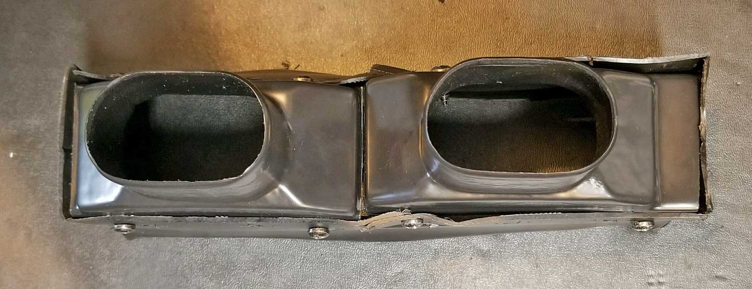
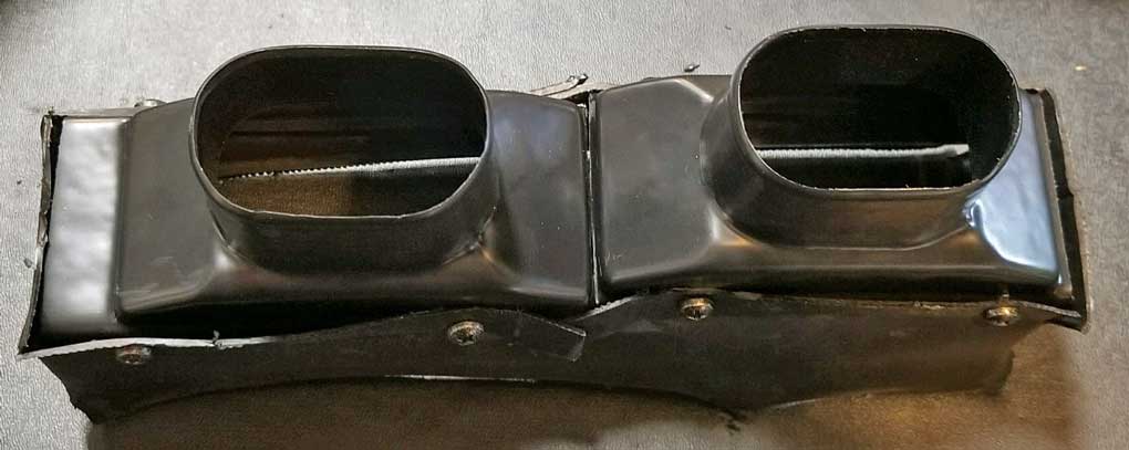
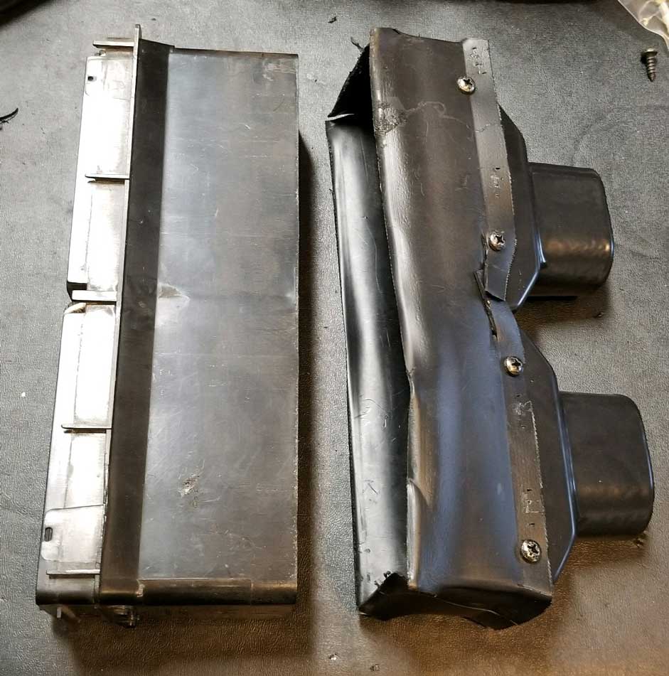
| TEST FITTING the EVAPORATOR BOX |
|


|

|
|
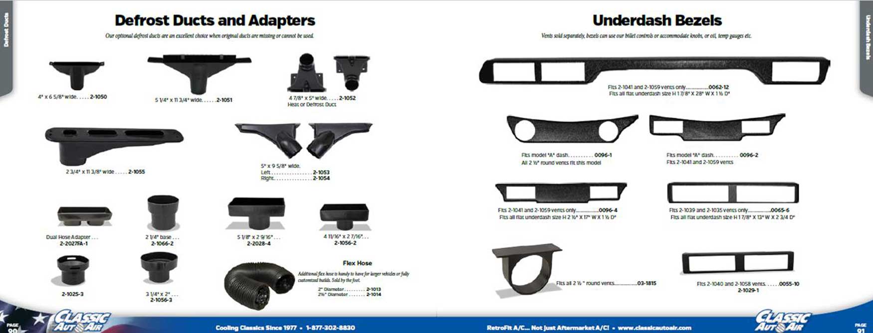
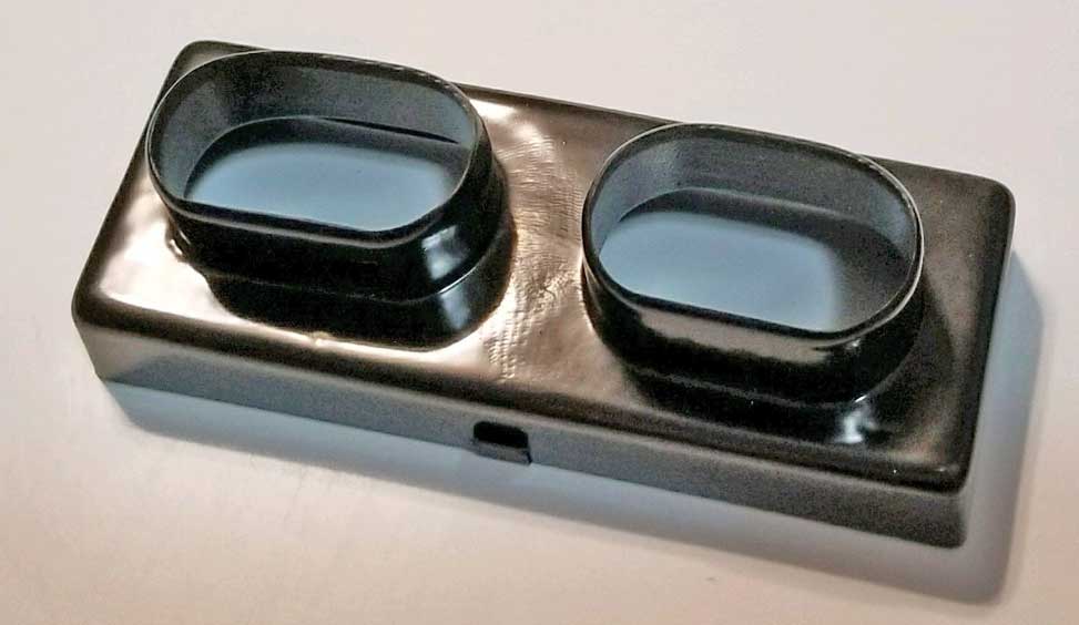
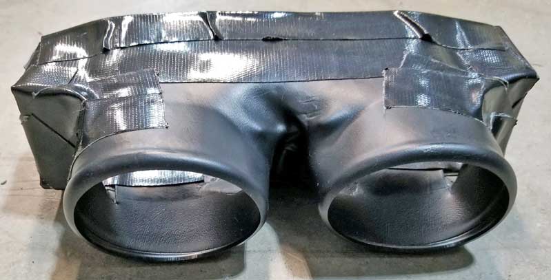
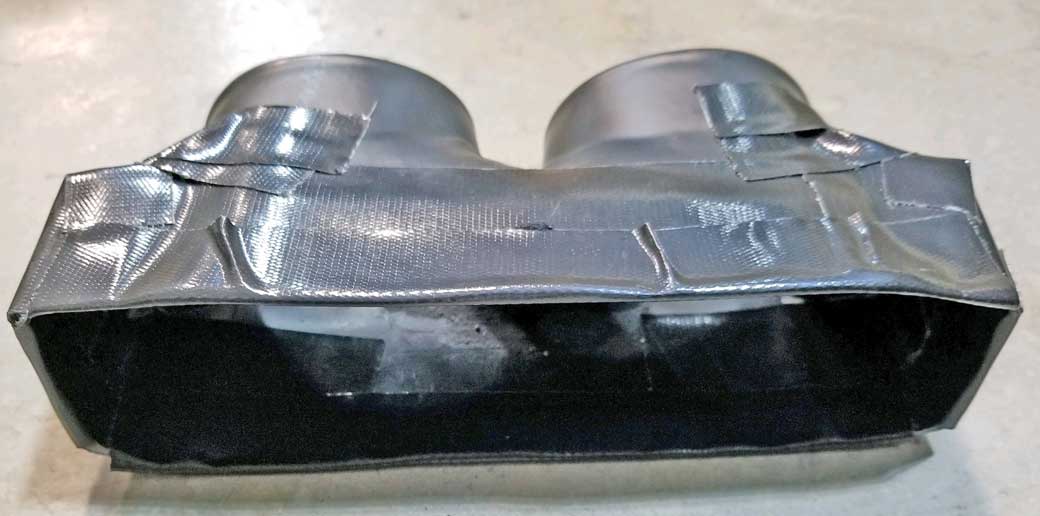
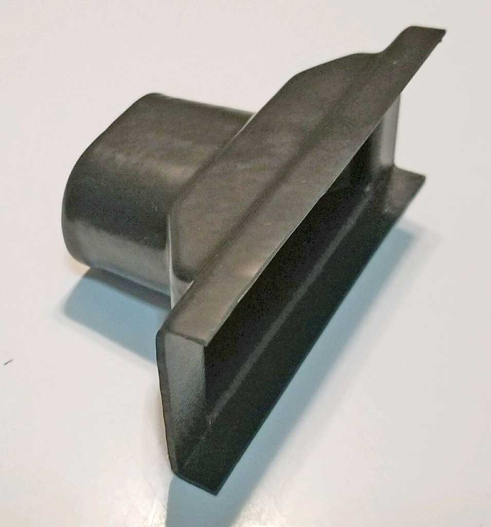 <<< They sent 4 of these and
they came in handy for adapting my defrost vents. Strangely, these were
NOT shown in their catalog. They are
similar to PN
2-2028-4 in their catalog. The adapters I
got were listed on my invoice as PN 0069-4.
Cost was $12.50
each. SIZE:
I measured them as 5 1/8 x 2 x 2 5/8 inches with an
oval tube inlet made for 2 inch hose. <<< They sent 4 of these and
they came in handy for adapting my defrost vents. Strangely, these were
NOT shown in their catalog. They are
similar to PN
2-2028-4 in their catalog. The adapters I
got were listed on my invoice as PN 0069-4.
Cost was $12.50
each. SIZE:
I measured them as 5 1/8 x 2 x 2 5/8 inches with an
oval tube inlet made for 2 inch hose. |
||||
|
|
||||
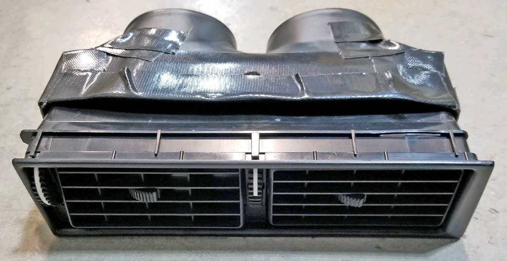
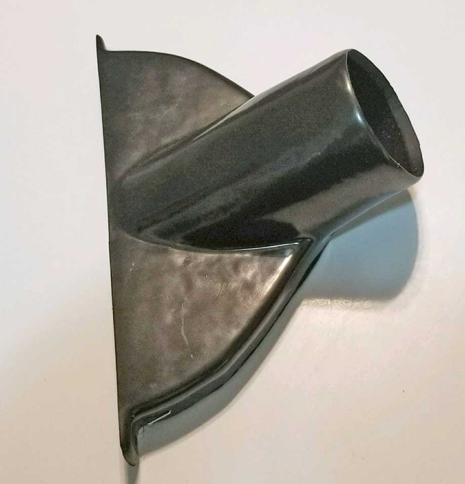 <<<
They sent 2 of these. These are defrost vents shown
in the catalog image as PN 2-1050. Cost was $17.50
each. SIZE:
6 3/4 x 4 inches. The top defrost outlet is about
5/8 inch wide. <<<
They sent 2 of these. These are defrost vents shown
in the catalog image as PN 2-1050. Cost was $17.50
each. SIZE:
6 3/4 x 4 inches. The top defrost outlet is about
5/8 inch wide. I did not use these. Michael Yount said he used some DIFFERENT defrost vents supplied by Classic Auto Air: Classic Auto Air PN 2-1053 and 2-1054. These are shown in the catalog pic above. He attached them under his dash using screws through the dash top. I decided to go a different route using the original 240 defrost vents that you'll see below. |
||||
|
|


|

|
|
|
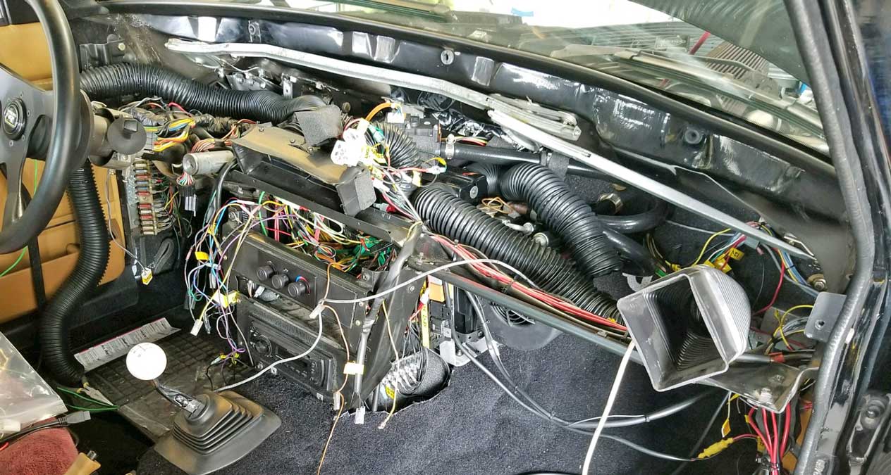
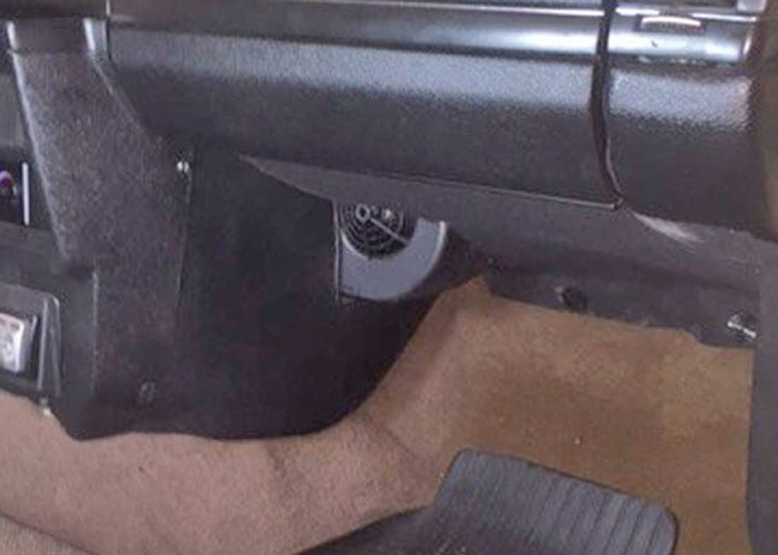
| DASH IS NOW IN. |
|


|
||||||
|
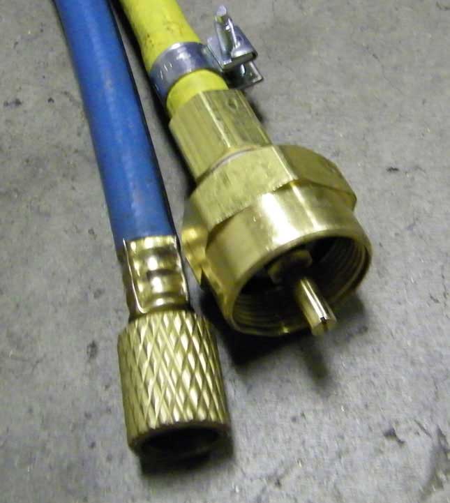
Classic Auto Air has a selection of refrigerant
hose parts, however their catalog did not have all
the fittings I needed. I ordered the below
hose parts from coldhose.com.
A parts inventory list with part numbers is listed below CLICK HERE. TRADITIONAL CRIMPING For hose fitting assembly, I already had a Mastercool hydraulic AC fitting crimping tool, which is used to crimp traditional beadlock AC barrier hose fittings. Beadlock hose is identical to the original AC hose used in the 240. This tool was expensive. I bought it years ago when I first began doing my own AC work. It can cost over $500. https://mastercool.com/product/71500/ Mastercool- 71500 Hydra-Krimp Hose Crimping Tool https://www.youtube.com/watch?v=ik7041RsTdg ALTERNATIVE If you decide to use a crimper, now there's a less expensive option for DIY AC mechanics. The Mastercool 71550 MANUAL hose crimper. It can be mounted to a vise or to a bench. Best of all it's only around $150. Or of course you can go to a hose shop and have your hoses custom made. You can expect to pay quite a bit for that service, so buying your own tools makes sense to me if you might be doing this more than once in a lifetime. https://www.youtube.com/watch?v=DHAHa9_UWQU
|
|

|


|

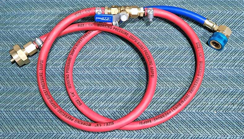
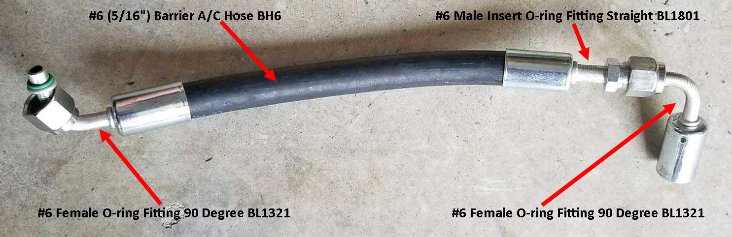
This list covers all AC hoses. All fittings are aluminum. Below items were ordered from coldhose.com.
|
|||||||||||||||||||||||||||||||
|

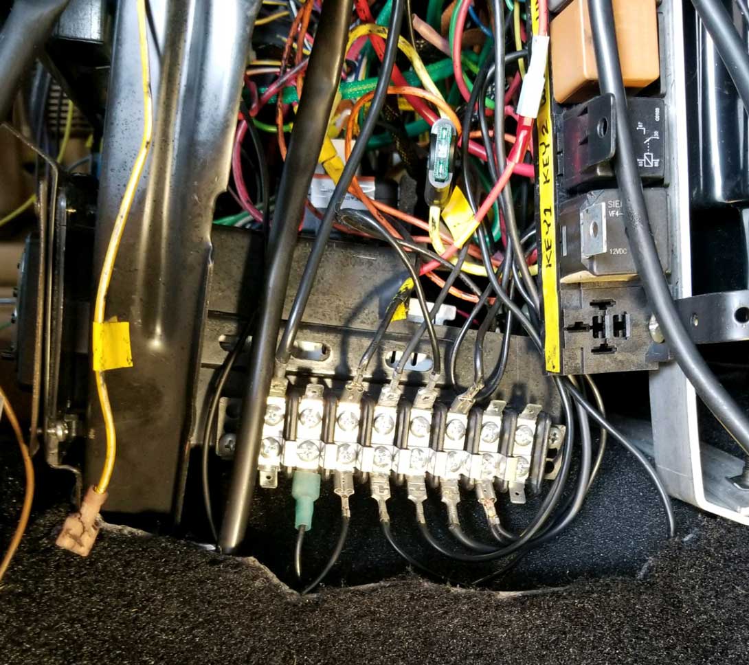
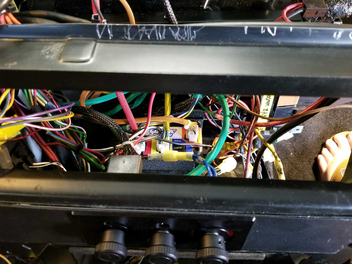
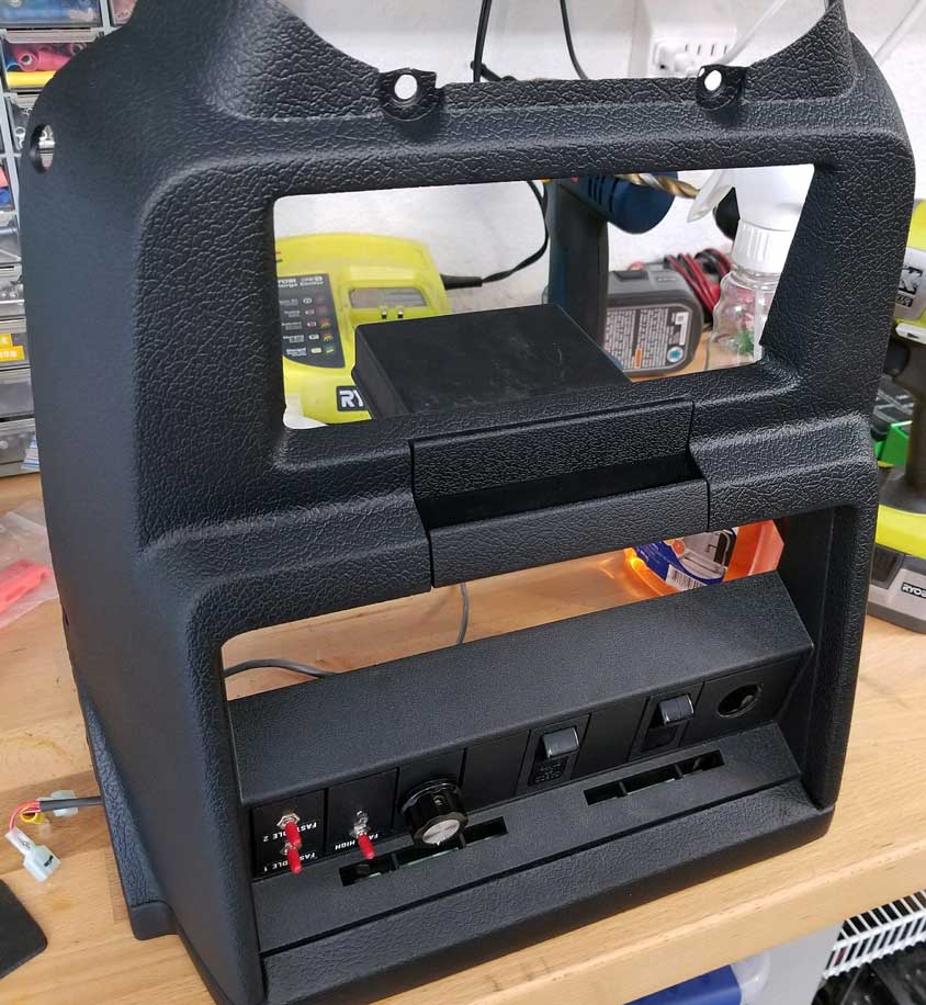
12V Key 1 has power when the key is it the key first power "ON" position. 12V Key 2 has power in the key second (or "RUN") position. There are no covers available for these distribution blocks. I made these cover custom because I wanted some protection for the hot leads. Details below. 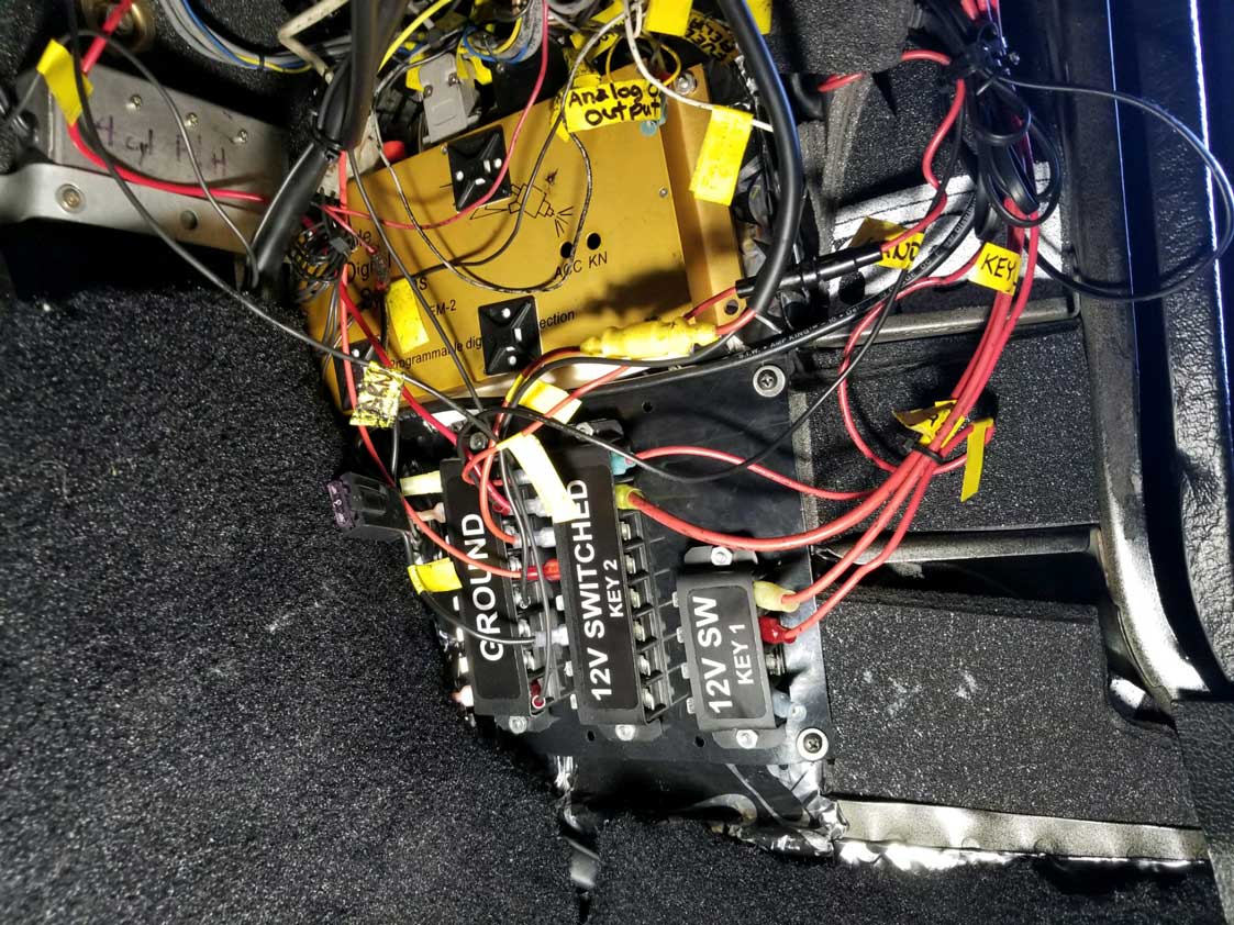 I made the covers by forming some inexpensive 1/32 inch gray PVC plastic sheeting I got from McMaster Carr: https://www.mcmaster.com/#8748K21. I then painted them black and added labels. That PVC sheeting may be formed easily with some heat from a hair drier or heat gun and it's easily trimmed with scissors. If you try this, make a mock-up cover out of cardboard first so you have a good template. 
|
| Buttoning Things Up |
|

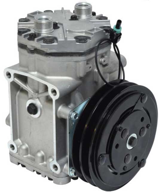
| Refrigerant Oil I used Ester Oil in my compressor as recommended by Classic Auto Air. R12 systems typically always used Ester Oil. You may find information online suggesting the use of PAG oil with R134a. Either can be used. Both are synthetic lubricants. The difference is that PAG oil comes in more than one viscosity. Ester Oil comes in only one type.
 Classic Auto Air has some specific instructions for charging their AC systems.
Why do I need to VACUUM the system first? Air conditioning systems don't like air. Air doesn't harm the system, but it's a lousy refrigerant, so you need to get it out of the system. Air conditioning systems don't like moisture either. Moisture attacks metal parts and will eventually cause the compressor valves and rings to degrade or fail. That's the main reason systems sometimes get vacuumed for hours. It's not the air so much as the water vapor that needs to be removed.
|
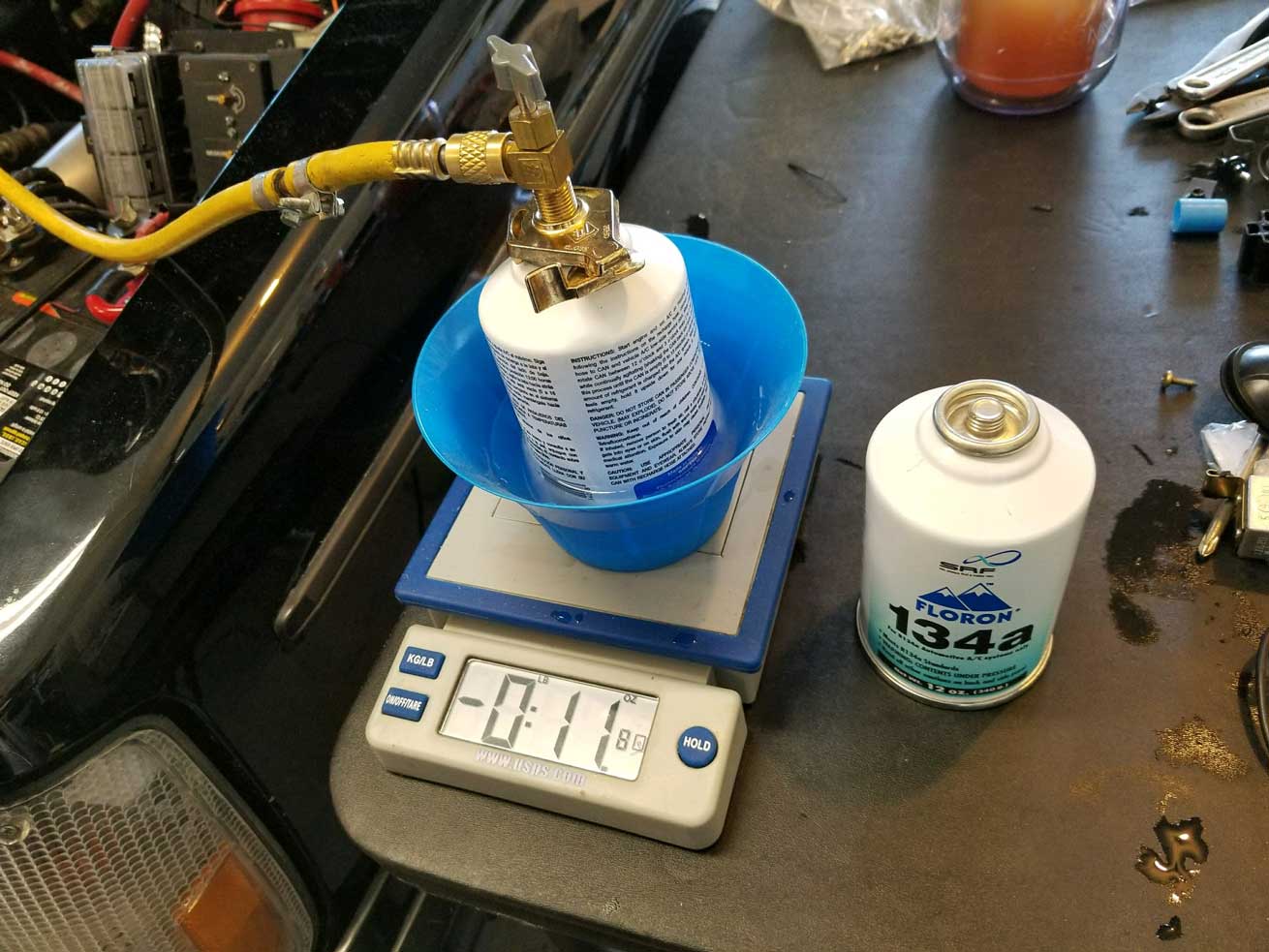
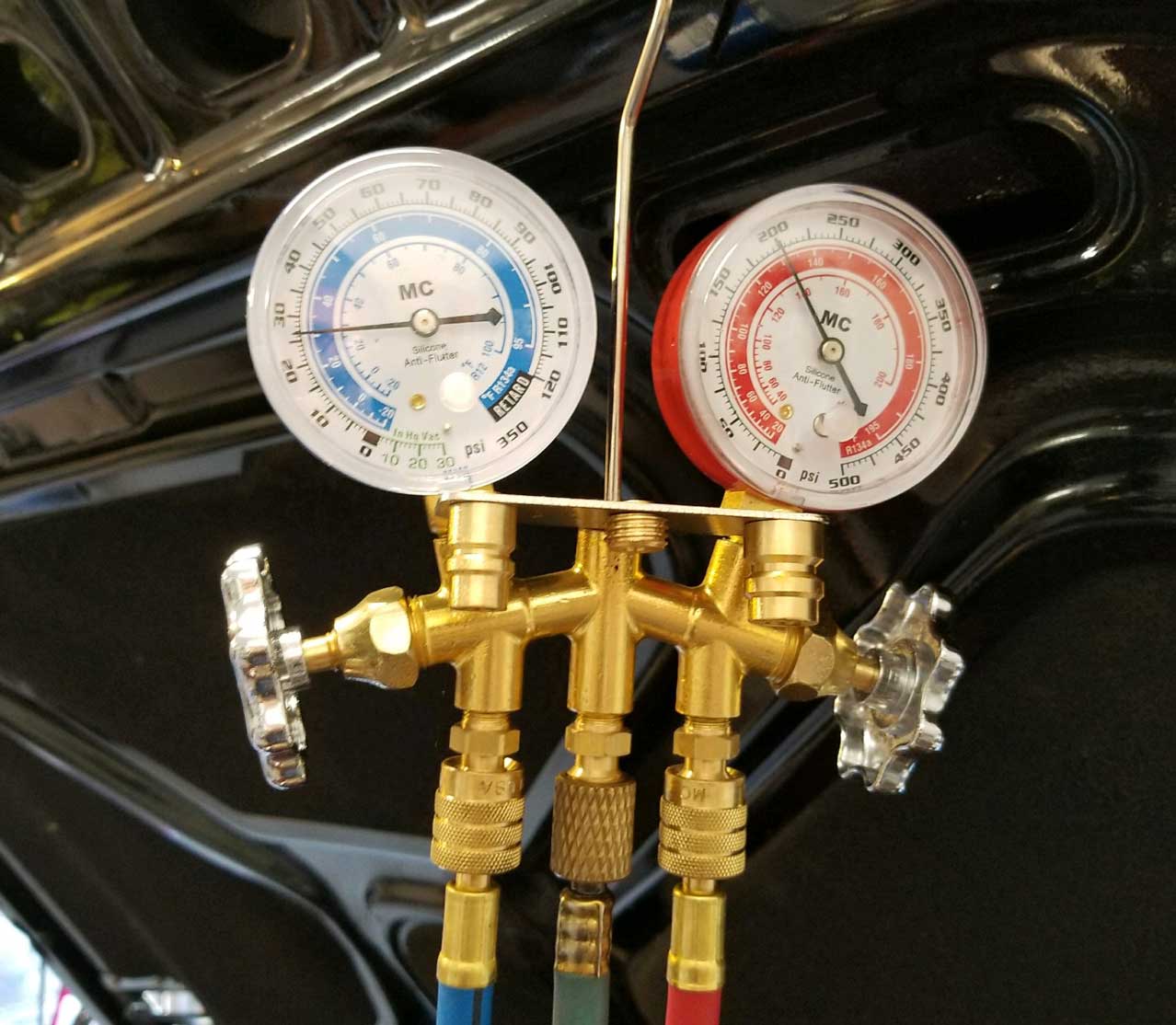
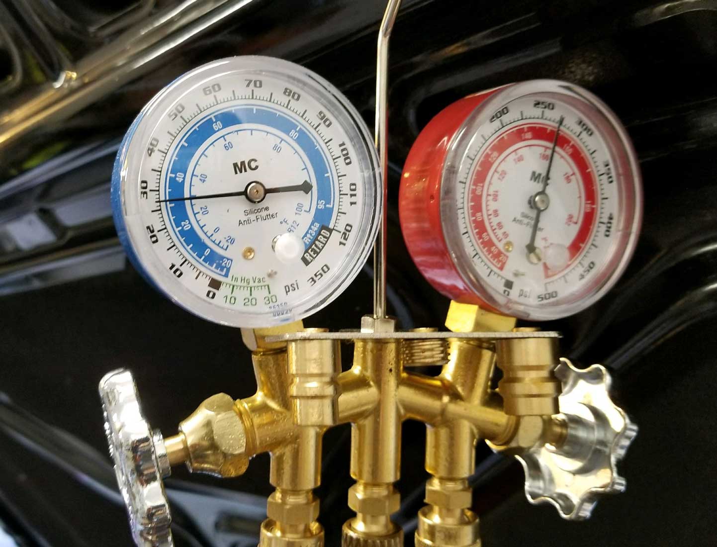 <<< Can #2 took about 20 minutes. Here are the final pressure readings after installing just under 24 ounces of R134a. R134a Low: 27 PSI. High: 270 PSI. |
|

|
| CHECKING FOR LEAKS |
This is
something that will ALWAYS be on your mind
when putting such a project
together. My system developed a leak
somewhere that allowed the refrigerant to
leak down in 24 hours. That's a pretty
fast leak. It makes you doubt the parts
you spent a fortune on, your tools and
your sanityin trying something like this.  <<< So
I
bought a can of R134a with UV DYE and a UV flashlight
on Amazon. <<< So
I
bought a can of R134a with UV DYE and a UV flashlight
on Amazon. |
||||||
|
|
||||||
| Observations
and
Results. I started with 134a (but did not end with it). |
||||||
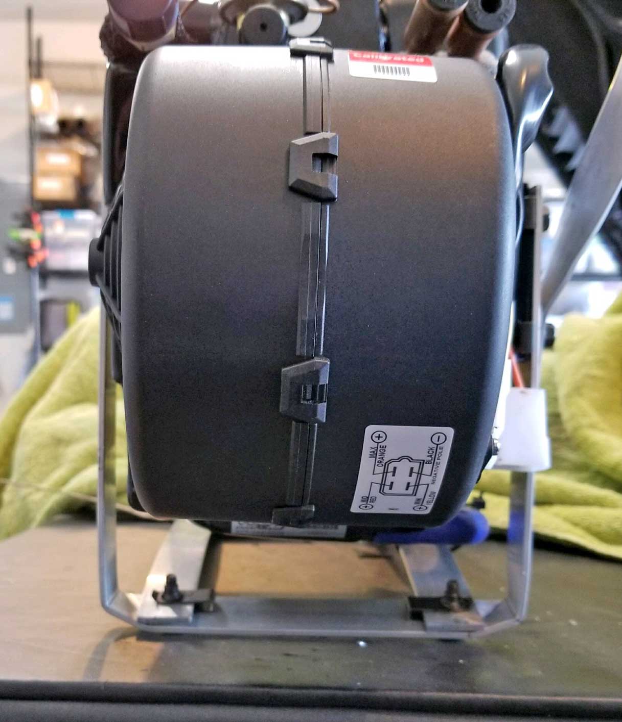
|
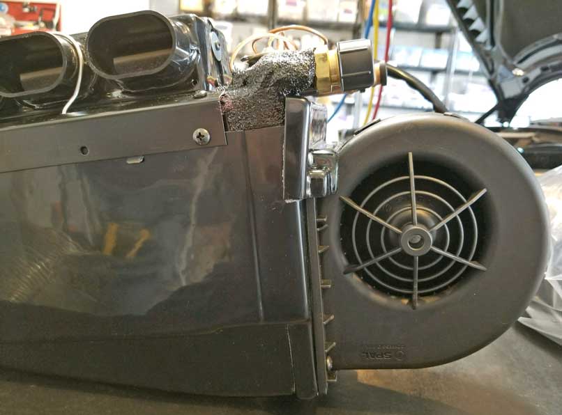
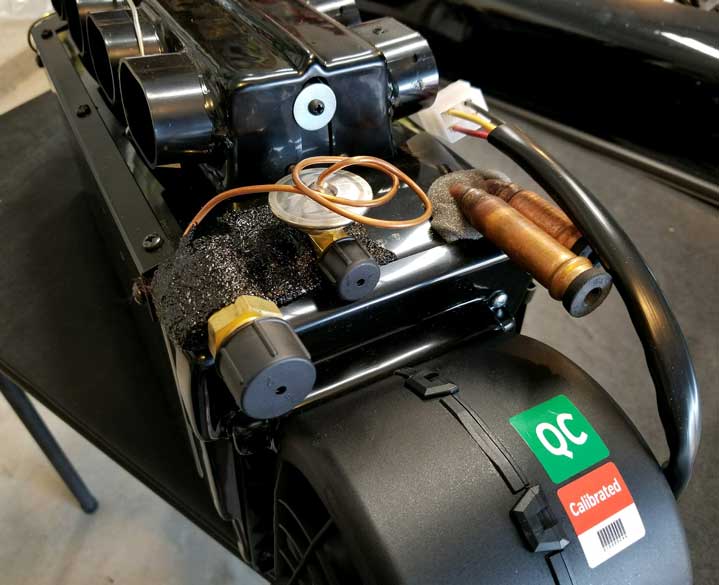
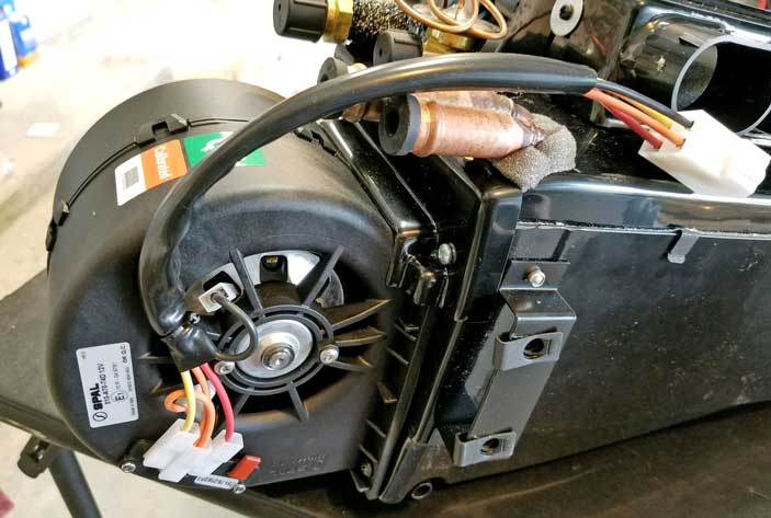
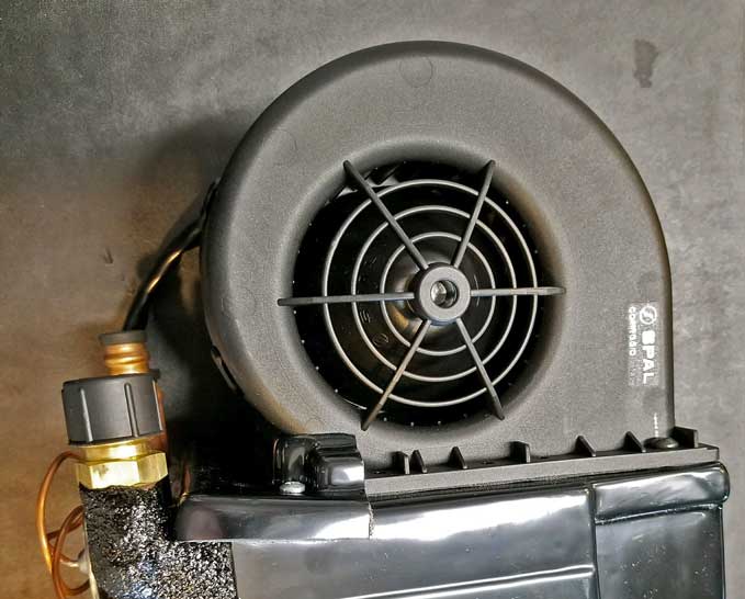
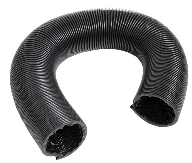
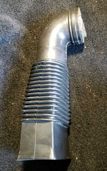
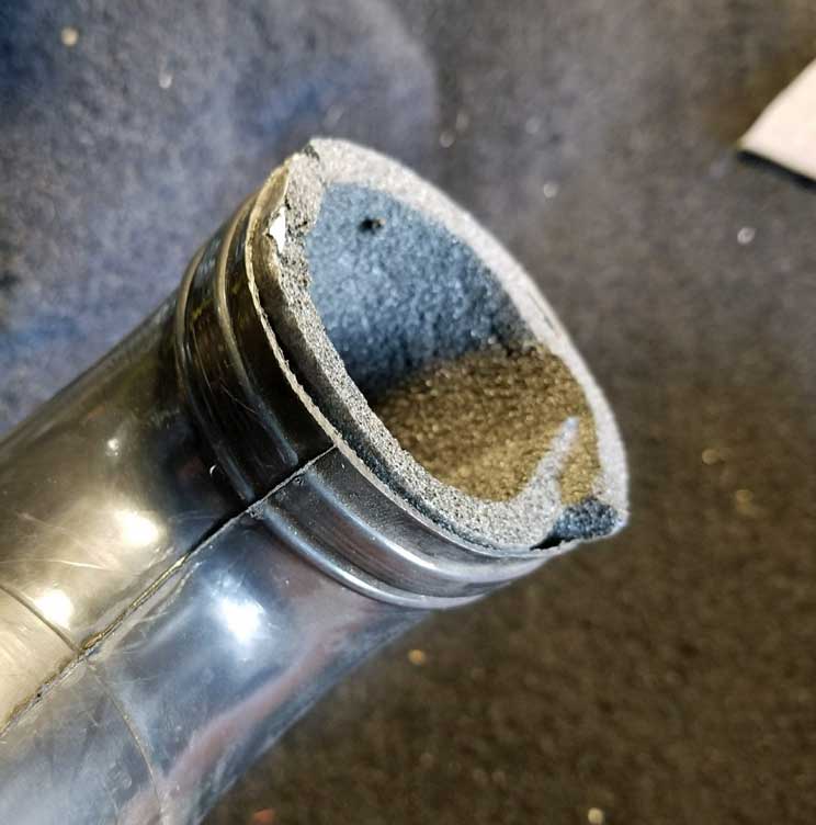
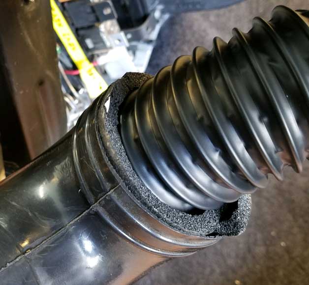
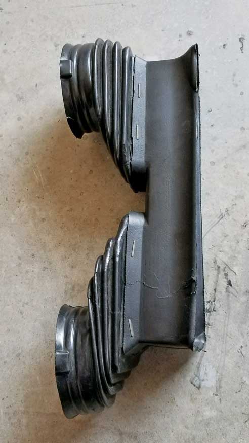
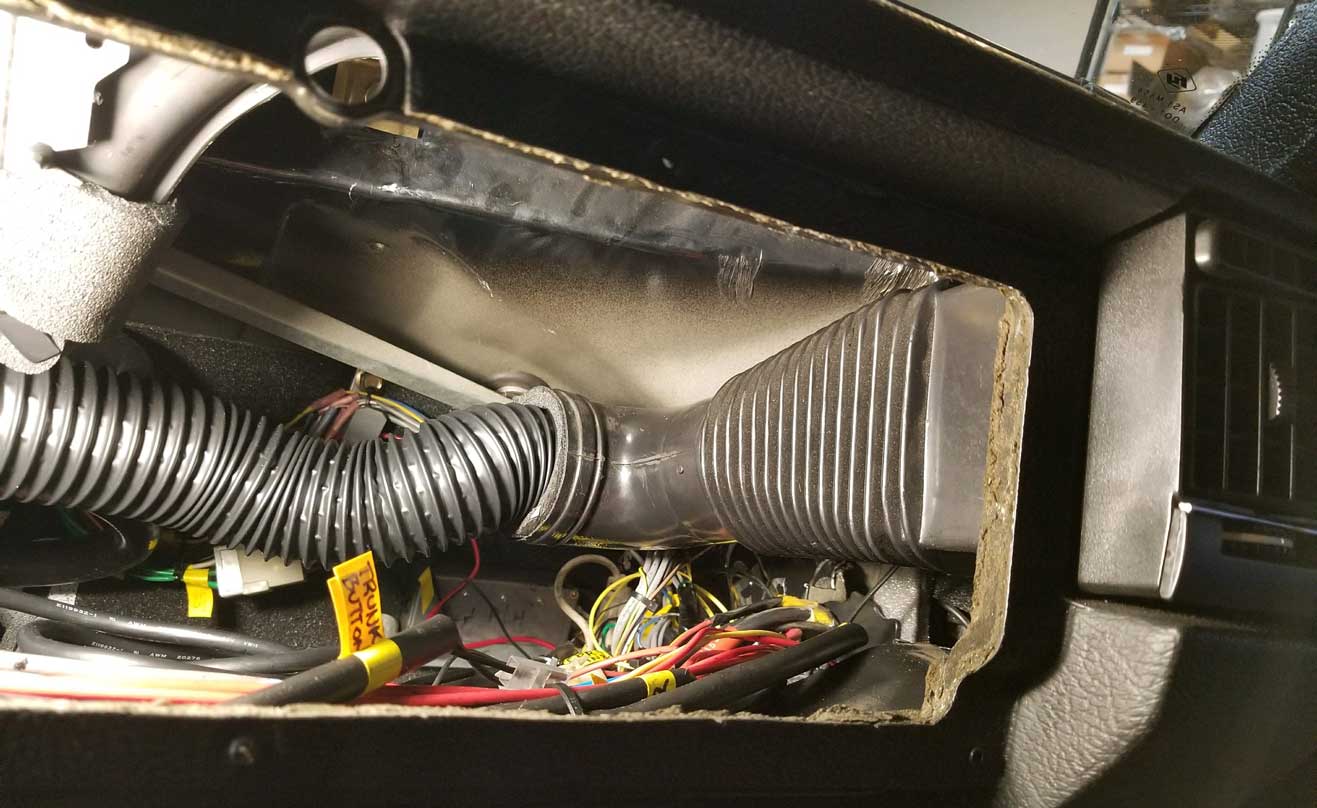
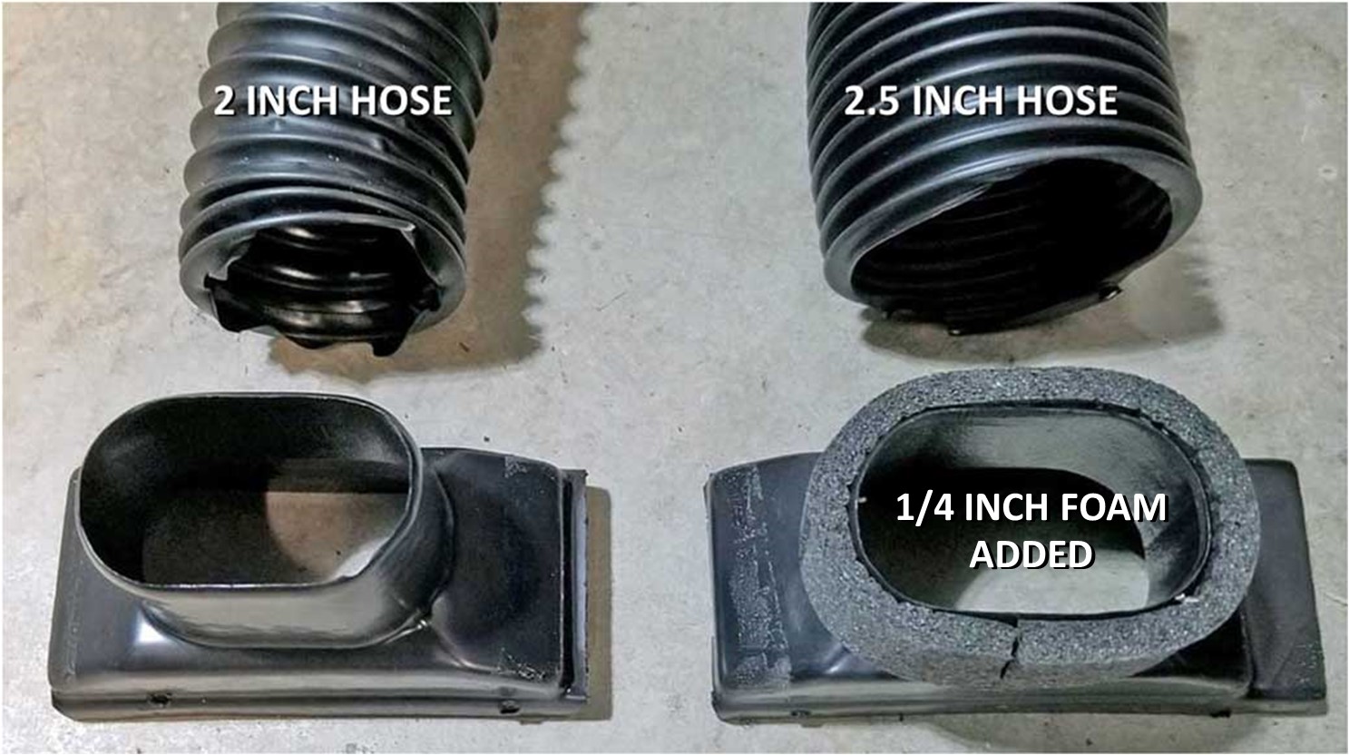
AIRFLOW OBSERVATION: The air turbine in this new AC unit is smaller than those in original Volvo 240 air boxes. That was easy to see since the new unit is more compact than the Volvo box. So I expected the airflow on HIGH setting would not be as powerful as the original Volvo unit and I was right. I can't offer a more precise quantification. If this is a deal breaker for you, then you should keep your original system. I did work out some solutions for improving airflow through the small duct hoses (installing larger ones). You can see those improvements HERE. Classic Auto Air specifies to use R134a in their systems. I've never been much of a fan of R134a. R134a is not as efficient as the old R12. But I did give it a good try in this conversion and tested it for a number of weeks.
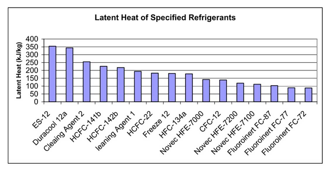
If you're into this AC tech stuff and want to learn about SUPERHEAT and SUBCOOLING (and R134a comparison to Duracool), the below diagrams will help. 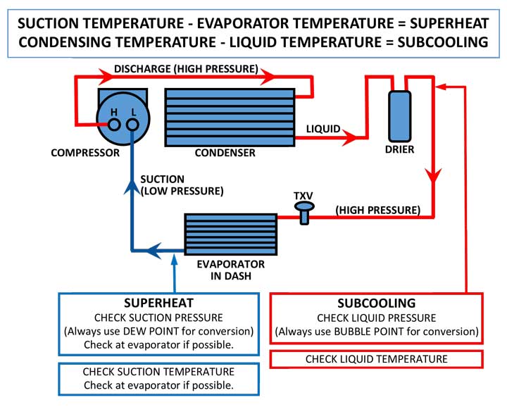 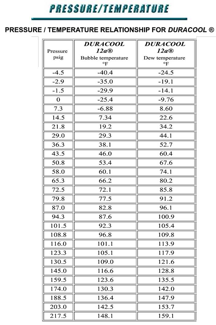
I've preferred using Duracool over R134a for a number of years. If you go to their site, you should READ THEIR FAQ SECTION to become more familiar. http://www.duracool.com/. Duracool is advertised to be 35% to 40% more efficient than R134a (it's more similar to the efficiency of R12). It produces significantly lower head pressures than R134a, using significantly LESS refrigerant. Duracool says that the ideal low pressure readings with compressor running are recommended to be between 28 and 38 PSI (varying depending on the ambient temps). They recommend that if the low pressure reading is too low, resulting in vent temps that are too cold, another ounce or two of Duracool can be added to bring those up. INVERTED CAN FOR MIXED REFRIGERANTS Duracool recommends this can to be inverted during charging. This is because Duracool is a MIX of more than one component and it will be more evenly distributed by inverting the can and allowing it to be charged as a liquid instead of as a gas when the can is upright. 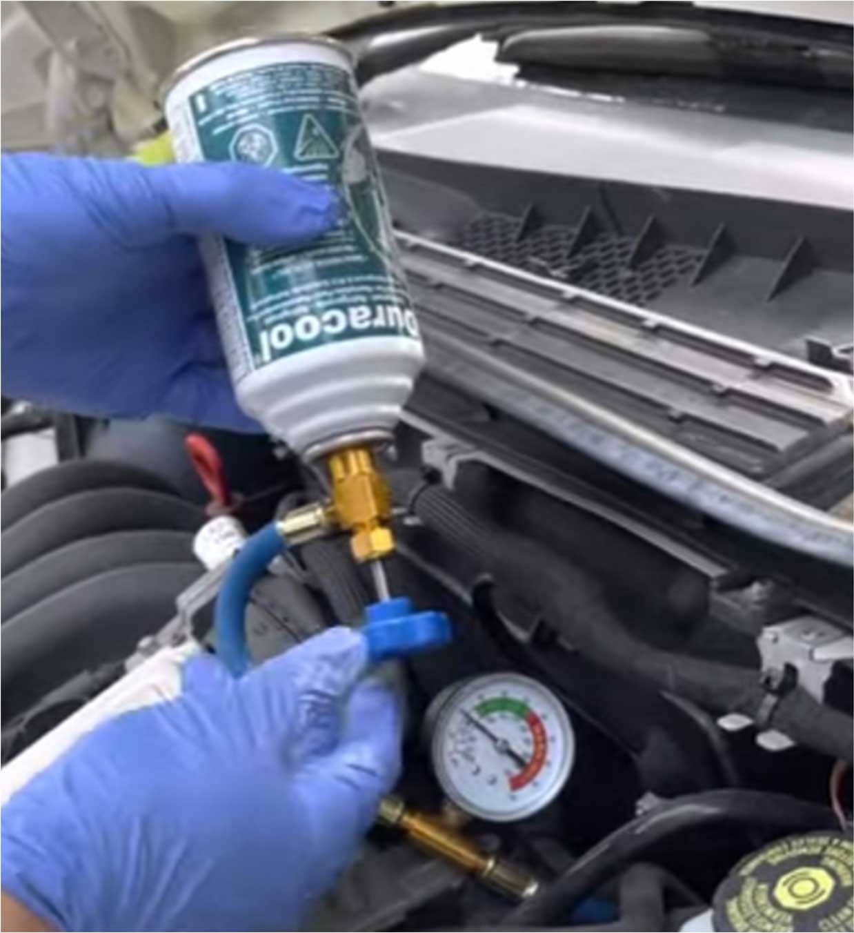 In MY opinion, if you're going to use this entire 6 ounce can, then charging as a gas is just fine and then it'll mix no problem after it's in your car. HOWEVER, If you're charging using a larger bulk bottle, then it will be more important to always charge inverted as a liquid to avoid depleting the bottle unevenly. Single component refrigerants, like R12 or R134a (or Propane or Butane by itself), may and should be charged as a gas with the can upright. I'm generally against recommending that anyone charge their AC system as a liquid like this, unless you're experienced enough to avoid damaging your compressor. If you are NOT experienced, I recommend doing more research or at least use lots of CAUTION. This is because if you don't use caution, you may inject an UN-compressible liquid into your running compressor, which has the potential to destroy it instantly. Feeding liquid refrigerant into a running system should, at the very least, be done very very slowly. If you have pulled a vacuum on your system because it was opened to the atmosphere for repair, Duracool recommends that a liquid charge to the suction (low) side of the compressor should occur initially with the COMPRESSOR OFF. Then one should wait about 30 minutes for the liquid to boil off to a gaseous state and then move on to the next step of adding more with the compressor on. The use of an AC gauge manifold set helps greatly to regulate the whole process and permit the system to be charged in a more precise and controlled manner.
NOTE: LESS DURACOOL IS REQUIRED COMPARED TO R134a (or compared to R12a). As mentioned, Classic Auto Air recommended 24 ounces of R134a for this conversion. The Duracool equivalent is about 10 ounces. A 1986 240, which uses about 2.9 lbs of R12, should only need about 16 ounces of Duracool. A 1993 240, which uses about 1.63 lbs of R134, should only need about 11 ounces of Duracool. Here's a table below showing precise conversions (from the Duracool website FAQ section). 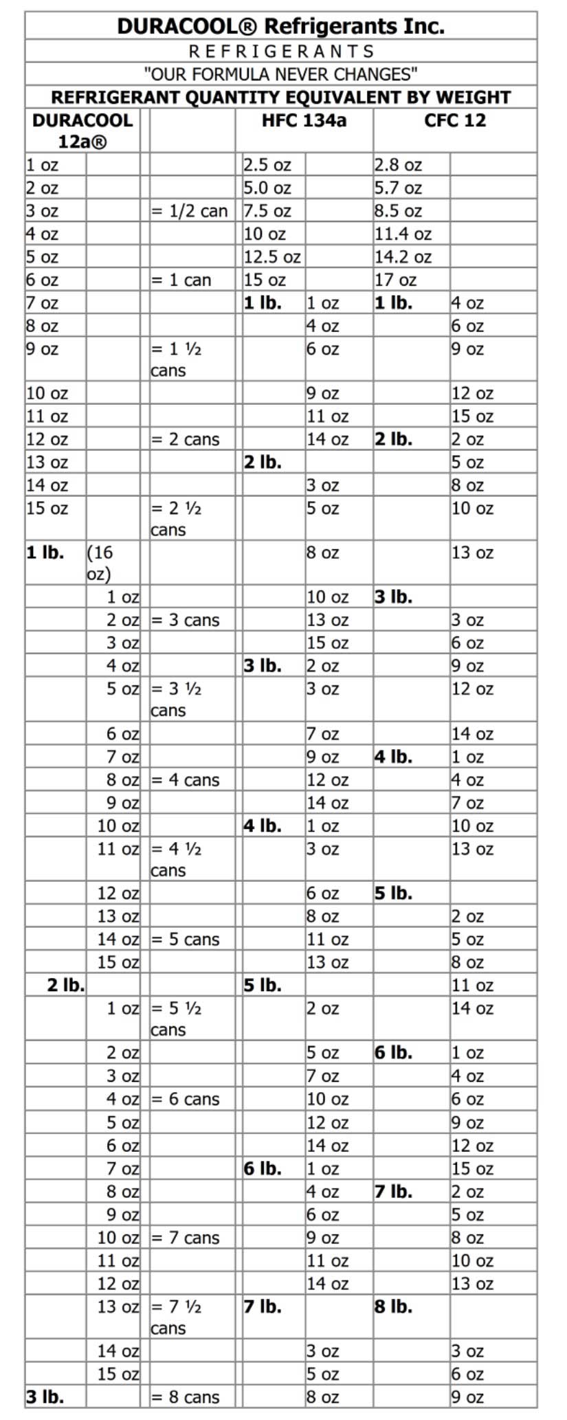
Here an information video from Duracool. (3:41 length) https://www.youtube.com/watch?v=E2ESleWa1nI MY ULTIMATE VENT TEMPERATURE PERFORMANCE WITH DURACOOL Duracool is more efficient that R134a and in my system, it gets considerably colder. This testing was done at idle and on the road. INITIAL IDLE TESTING: The first Duracool tests were done at end of summer 2017. With Duracool (while idling) I saw a low vent temperature of 27º Fahrenheit with an ambient temperature of 80º F. That ambient temp was not very high, but by this time cooler fall temperatures were coming. This vent temperature was recorded at idle in my garage with the fan on the lowest setting. As the AC continued to cycle on and off, the vent temperature ranged between 27º and 32 º F. Increasing the fan speed tends to bring the vent temperature up several degrees because more warm air is being pushed through the evaporator. When summer 2018 came along, I did more testing with high ambient temperatures of more than 100º F. After initial start-up in my garage, vent temperature at idle was 46º F. Since 46º F felt pretty good with that kind of outside temperature, I was curious about my wife's new Subaru Forester. So I tested the Subaru AT IDLE with the same 100º F plus outside temperature. It recorded a vent temperature of 43º F. My 240 wasn't too far behind that. 2019 SUMMER ROAD TESTING: While road testing at 55 mph with an ambient outside temp of over 100º F, I have recorded low vent temps of 25º F (PHOTO BELOW) however more common vent temps seemed to be around 31-32º F. Yes, I will agree with you that allowing the temp to dip below freezing can introduce problems. See the below section on preventing FREEZE-UPS. NET TEMPERATURE DROPS: So it appears my potential vent temperature drop below ambient is around 53º-55º F at idle and around 68º-74º F degrees at 55 mph. This is awesome cooling compared to before! Yes, this kind of performance makes me smile. 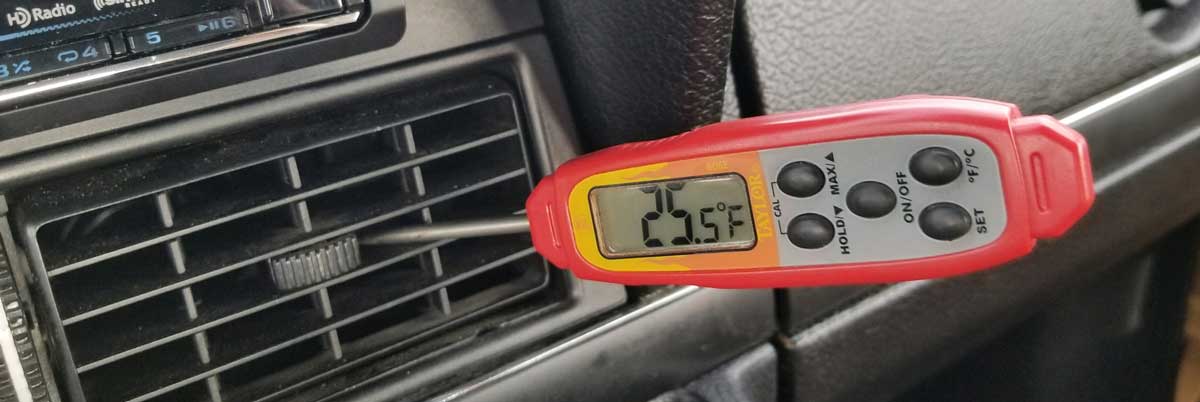 Any temps below freezing can have a potential negative affect. You should read the BELOW section on preventing freeze-ups and how I manage this.
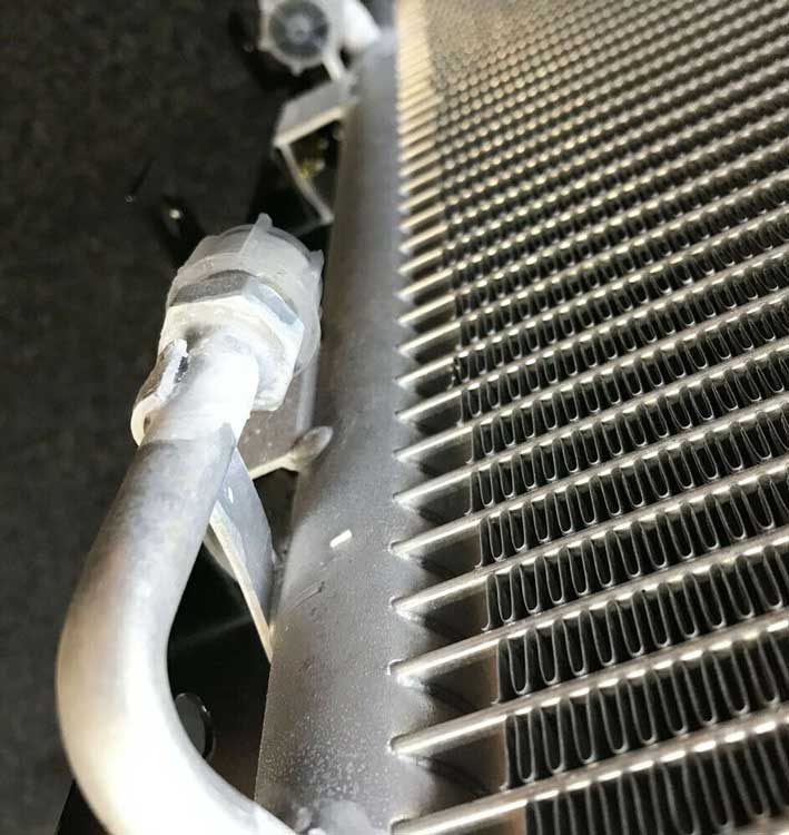
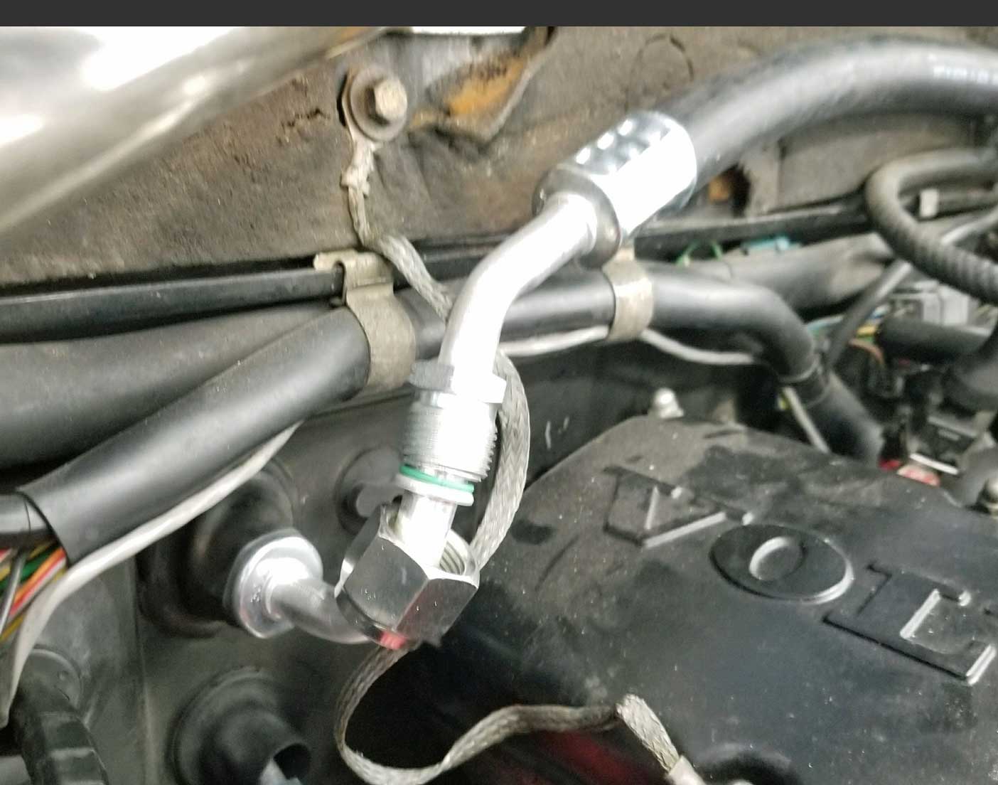
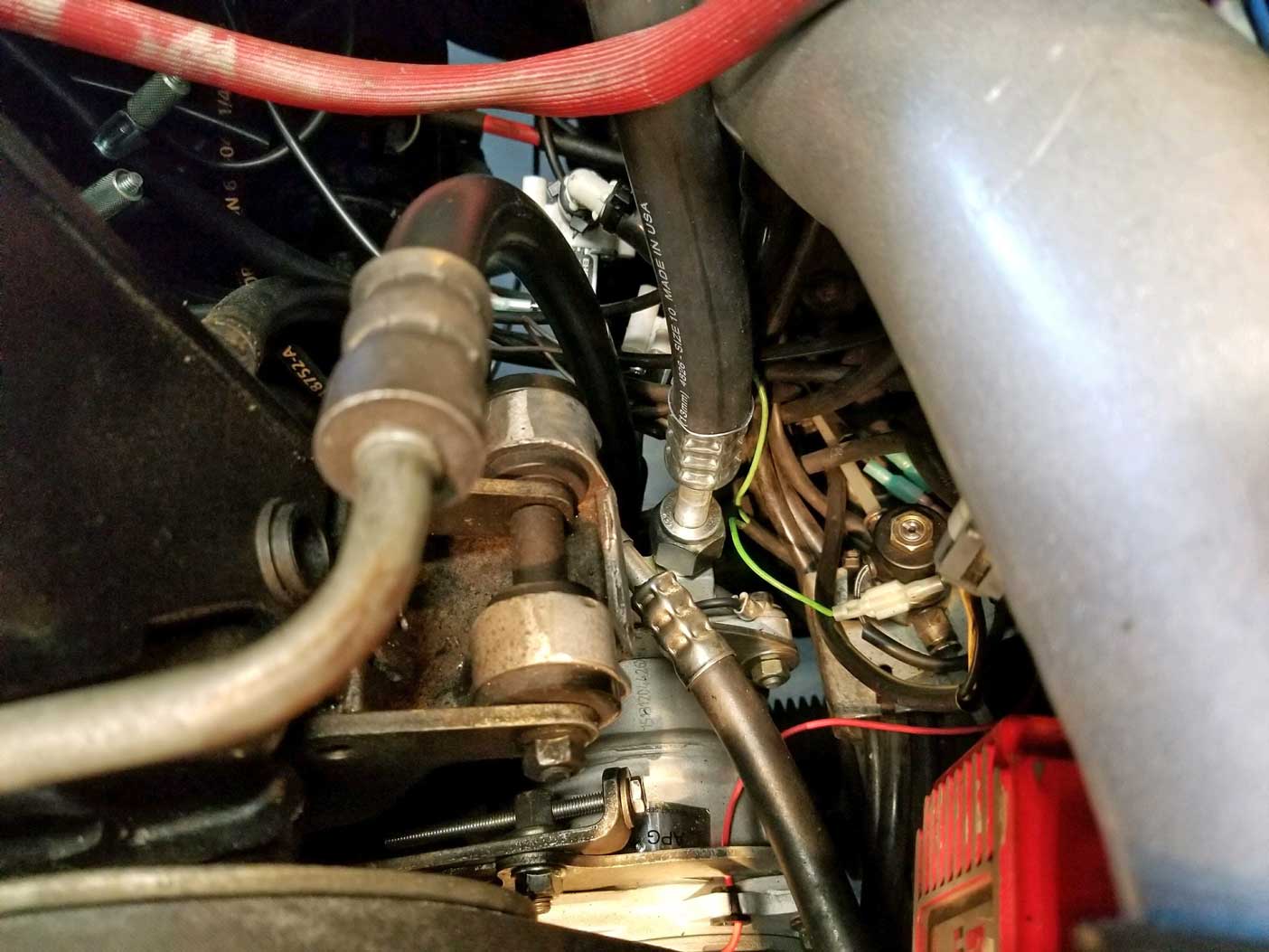
There can be TWO different types of freeze-ups in an auto AC system. FREEZE UP type 1. This occurs when moisture in the air on the OUTSIDE of the evaporator turns to ice. This can happen when the outer surface of the evaporator drops below freezing and begins freezing the condensation moisture collecting on it. Small amounts of frost on your evaporator will not cause problems and when the frost or ice melts, it'll drain out to the bottom of the car. If the evaporator gets or stays cold enough for a long enough time, ice can continue forming much heavier. If enough ice forms over time, it can eventually block the flow of air going through the small evaporator coil spaces. This blockage will result in poor airflow through the vents and any air coming through may not be as cold as it should be. Since you probably can't climb under your dash to look for ice on your evaporator, there are other ways to detect ice. A sign of ice forming can be found under your hood on your AC suction hose (low pressure hose). This image below isn't a Volvo, but it shows what you can find. This is frost accumulating on the pipe or hose coming from the firewall. This hose goes to the compressor or to the accumulator on a later 240. This is the return (suction) line for refrigerant returning from the evaporator to the compressor. Ice forming on this line means things are usually too cold. Most often you won't see ice like this on a normal working AC system, but instead you'll see light frost or cold beads of water condensation. 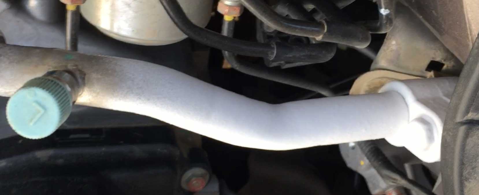 Freeze up conditions are temporary and will not damage the system. It will, however, damage your sanity. FREEZE UP type 2. Another type of freeze-up can occur if there are traces of moisture INSIDE your system. If your evaporator dips below freezing (32º Fahrenheit) and if there are any traces of moisture in your refrigerant, that moisture can crystallize (FREEZE) as it enters the evaporator coil. If enough ice forms at the coil entrance, it can temporarily block the flow of refrigerant. If this occurs, then the first symptom will be the AC vents expelling ambient temperature air. 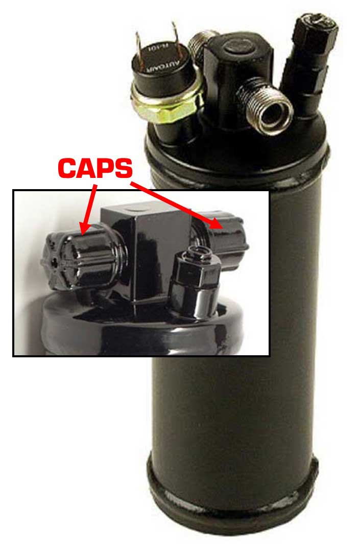 If you
were to connect a pressure gauge manifold to your system when this is happening, you would see
reduced pressure in your low pressure side (the line between the
evaporator and compressor). This reduced pressure can even become a
vacuum if the blockage in your evaporator is severe enough. If this occurs,
there's not much you can do except turn it off and wait for it to thaw out, which can take
hours. This INTERNAL freeze-up can be
prevented or reduced by thoroughly vacuuming your system to remove air
(and moisture) before charging it with refrigerant. Also
replacing the receiver/drier canister will be a good idea if you suspect that an internal freeze-up
has occurred, or if the drier canister hasn't been replaced in a long time (or
ever), especially
if the system has been opened or serviced and it wasn't replaced during
that service. The drier canister contains a desiccant for moisture
removal. If you
were to connect a pressure gauge manifold to your system when this is happening, you would see
reduced pressure in your low pressure side (the line between the
evaporator and compressor). This reduced pressure can even become a
vacuum if the blockage in your evaporator is severe enough. If this occurs,
there's not much you can do except turn it off and wait for it to thaw out, which can take
hours. This INTERNAL freeze-up can be
prevented or reduced by thoroughly vacuuming your system to remove air
(and moisture) before charging it with refrigerant. Also
replacing the receiver/drier canister will be a good idea if you suspect that an internal freeze-up
has occurred, or if the drier canister hasn't been replaced in a long time (or
ever), especially
if the system has been opened or serviced and it wasn't replaced during
that service. The drier canister contains a desiccant for moisture
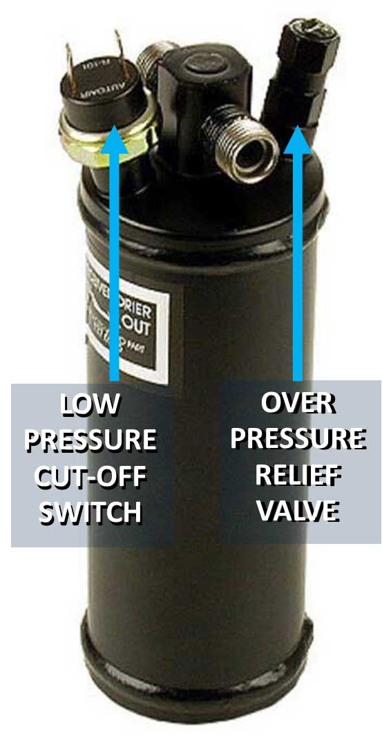
removal. A new drier canister is not expensive and replacing it should be a matter of maintenance when the system is worked on. Years ago when I was experimenting with PROPANE in my original Volvo AC system (CLICK HERE), I was able to get very, very cold AC at times, but I eventually gave up on propane because performance was too inconsistent. Considering that experience now, I think the problems I experienced might have been because of internal freeze-ups, since at one time I recall I getting under the dash with my laser temp reader and I measured the evaporator at 17º Fahrenheit. Who knows? If I had found the below temperature controller back then (if it existed yet), my experiments with propane might have been a success. RECEIVER/DRIER Canister: An old receiver/drier can become useless if the desiccant inside becomes saturated with moisture. This can easily happen if the system was ever left open or it the receiver/drier was sitting on a shelf for a long time and the seals weren't 100% air-tight. If you remove the sealing CAPS on a new receiver/drier and you don't hear the "PSSSSST" of rushing air, then it was not properly sealed. So maybe you're thinking that YOUR AC system isn't getting anywhere near cold enough to freeze. This might be true, but keep in mind that vent temps can be higher than your evaporator exterior temps. So even if you might not be concerned about freeze-ups, there are ways to improve things. Keep in mind that my current Classic Auto Air system was designed to use R134a and I did use that at first, but after I got disappointing results, I switched to Duracool R12 replacement and that got the temperature down substantially. |
||||||
| EVAPORATOR TEMPERATURE CONTROLLER Injecting some higher tech into old school AC control. |
||||||
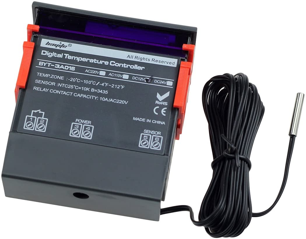
2020-2022 Updates Here's a new device I've been using for a while to control my evaporator temps and prevent it from getting TOO COLD. This is the BAYITE TCF-3A035 12V DC Digital Temperature Controller (in Fahrenheit) with internal 10A Relay and Sensor. It can be found here: https://www.amazon.com/gp/product/B011VGAPOC/. Cost: $18.00. There are nearly identical controllers out there from different sellers, but some versions use 110v AC, so avoid one of those if being used in a car. You can search "12 Volt DC Digital Temperature Controller" and you'll find them. |
||||||
| Why would I need to better control my evaporator temperature? I'm using this device to monitor the temperature of my evaporator outlet pipe and to allow me to see the evaporator pipe temperature. Before using this I found that my evaporator was been getting considerably colder than 32º Fahrenheit at times.The main reason for this is because I'm using Duracool, which is considerably more efficient than R134a, which the Classic Air AC system was designed and calibrated for. |
||||||
| The programming
functions for this unit allow me to program it to cut power to the AC
compressor if my evaporator becomes too cold. I have the sensor tip taped to the outside of my evaporator outlet pipe under my dash. I then insulated it with some foam tape. The evaporator outlet pipe is the one that goes to the low pressure hose that returns refrigerant from the evaporator unit to the compressor. 
 This device is small, about 3 inches wide. Programming it was not difficult once you read and re-read and then absorb what the instructions are telling you. For this type of programming you would use COOLING MODE, which I have circled on the second image below of the CONTROLLER INSTRUCTIONS (click here). When I want maximum cold AC, which is usually what I want, I can set the programming to allow the AC compressor to run normally until the evaporator dips to 32º Fahrenheit. It then CUTS the compressor power and remains OFF until the temperature rises to 34º. This OFF-ON gap can be as low as one degree or any custom setting you like. This device does an excellent job of regulating temps and I have not experienced a suspected freeze-up since I began using it. Here's a video I made below showing how this controller regulates the AC temperature. NOTE: That on/off switch on the right side is not part of the controller. I added that to switch off the controller power if needed. I thought that might come in handy, but so far I've never needed to switch it off. https://www.youtube.com/watch?v=Mh6E2dmDZfw WIRING DIAGRAM FOR MY INSTALLATION 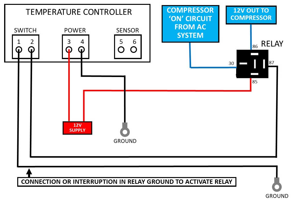 Here's a simple wiring diagram I made for my use of this device. This controller simply INTERRUPTS or CONNECTS the ground circuit for the relay I'm using to turn on the AC compressor. QUESTION: Can you use a device like this with any normal factory Volvo AC system? Yes, OF COURSE. If you somehow manage to get your normal AC to get super cold and you're concerned about it getting TOO COLD, this device would work just fine. I know that some Volvo AC systems, such as the later ORIFICE TUBE systems, are capable of getting super cold, especially if you use a hydro-carbon refrigerant, such as Duracool. QUESTION: Can I adjust the set temperature on this unit while driving without having to push a bunch of buttons to enter a programming mode? YES you can.  Simply press the SET button. The set temperature will display. Then press the UP or DOWN button to change it. Then leave it and the unit will change back to default display in about 5 seconds. Your new SET TEMPERATURE has been changed. NOTE: The RED LAMP next to "WORK" is letting you know the controller has switch ON your AC. When that lamp turns off, the controller has switched it off. Here's a video I made below showing how the SET TEMPERATURE is quickly changed if needed while the AC is running. https://www.youtube.com/watch?v=nGsv8dY3j-g If you have questions or decide to try one of these with your AC, let me know how it works for you. Send me an email. CONTACT CONTROLLER INSTRUCTIONS Here are images below of the instructions and programming guide. I circled the area in an orange box that I used for setting the cooling programming on mine. CLICK IMAGE FOR LARGER PHOTO. 
 A downloadable or printable PDF of these instructions is here: https://www.davebarton.com/pdf/BayiteTCF3A035TempController.pdf |
| LATEST ASSESSMENT |
I've been using this system along with the above added TEMP CONTROLLER above for three years. This includes thousands of miles of driving with a number of trips across the entire country. So far it seems to work really well. During road tests with outside temps of 100°F plus, my AC vent temps have been consistently at mid to low 30s Fahrenheit at highway speeds. Before, WITHOUT THIS TEMP CONTROLLER, my evaporator would definitely dip well below freezing (because that can happen with Duracool). So this device has been very successful at stabilizing temperatures to prevent freeze-ups. If you've done an AC upgrade to your Volvo and you can share it or if you're thinking of doing something like this, please email me. I'd like to hear all about it. Also, if you have any questions or suggestions to improve the information in this page, please let me know. Thanks, Dave CONTACT |
|
|
||||
| davebarton.com |
prancingmoose.com |
240turbo.com |
Special Emblems |
|
| Prancing
Moose Stickers |
Volvo
Stickers |
Body/Chassis/Engine
Labels |
240 MODS and FIXES Page | |
| Other Car Brand
Stickers |
Steering
Wheel Labels |
Center Cap Labels/Overlays |
Cool Volvo
Products |
|
| Grill Labels/Overlays |
Volvo Wire
Harnesses |
Conversion Harnesses |
Harness
Parts/Connectors |
|
| Volvo Relays |
Coil Repair
Harnesses |
240 Window
Scrapers |
740/940
Window Scrapers |
|
| Adjustable Voltage
Regulators |
Horn Buttons |
240 Odometer
Repair |
740 Odometer
Repair |
|
| Volvo Gauge
Faces |
740
Turbo/Boost Faces |
240 Black Door Vinyl |
850 Odometer
Repair |
|
| ALTERNATOR Page |
240 Power Mirrors - Switches |
240 Oil Cooler Page |
240 Fuse Panel Page |
|
| Group A
Racing 242 Turbo Page |
240 Hydraulic Clutch | Fuel Pump RELAY Page |
240 Headlight RELAY Page |
|
| Used Parts & Extra Stuff for sale |
CRIMPING Page |
240 Ignition Page |
240 Headlight Page |
|
| 240 Gauge Electrical Diagrams | 240 REAR END Page | Yoshifab Catch Can Install | 240 TAILLIGHT Page | |
| Side Marker
Lights Page |
Gentex Mirror Upgrade | Yoshifab Drain Tube Install | Modified 240 Favorites | |
| SoCal Salvage Yards | Unleaded Racing Fuel | B26FT Stroker | Dave's 245 Spec Page | |
| 240 SUSPENSION Page | 240 Lowering Page |
240 Windshield Page |
240 WIPER Page | |
| 240 BRAKES Page |
240 Dash Top Gauge Pod | Cadillac 4-Note Horn Install | 240 DYNAMAT Installation | |
| 4 Speed Fan
Controller |
Electric Cooling Fan
Page |
BRUSHLESS Cooling Fan Page |
Tropical Fan
Clutches |
|
| 240 AC Page | "KOMFORT BLINKER" Upgrade | T5 Trans Conversion Page | 240 Engine Mount Page | |
| 240 VIN Page | Stepper Idle Valve Page |
Vacuum Diagrams | 240 HOOD Page | |
| 240 Exhaust Page | 242 Power Vent Window Project |
EFI Volvo Pin Function Diagrams |
Favorite Links | |
| R-Sport
Apparel |
Prancing
Moose Apparel |
Volvo Meet Photo Albums | Texas Volvo Meets and Events | |
| Ordering Instructions | Policies | PAYMENTS Page |
Mojave Road Trail Map Page |
|
| Returns | Shipping | Shopping Cart Troubleshooting | Contact Us |
|

|