| 2 4 0 T U R B O . C O M D A V E ' S V O L V O P A G E
|
||||||||||||||||||||||||||||||||||||||||||||||||||
| 2 4 0 T U R B O . C O M D A V E ' S V O L V O P A G E
|
||||||||||||||||||||||||||||||||||||||||||||||||||
| This page offers a bunch of useful knowledge about Volvo 240 ignitions that I have learned and compiled over many years. If you have any comments or questions or if you can help to improve this information, please email. CONTACT |
| 240 Factory Ignitions |
| I
will not be getting into older breaker points distributor ignitions.
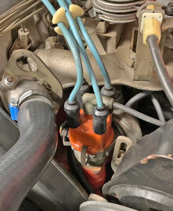
I'll begin with early Volvo 240 Breakerless Electronic Ignitions. Most 240s
imported to the US and Canada came with
electronic ignitions. BELOW: Firing order and distributor rotation comparison between the B20 and later B21-B23-B230.  
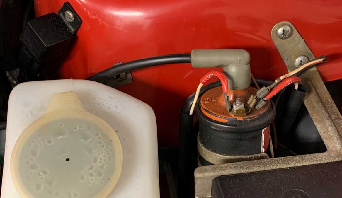
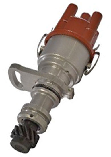
Breakerless Electronic Ignitions were found in the mid-1970s 240s and some early 1980s. It was fitted to all Bosch K-Jetronic injection equipped 240s with and without turbos up to the1985 240 Turbo. This is a Bosch ignition system with a RED distributor cap. It had an ignition control unit (ICU) placed under the hood (image below). This Bosch ICU is smaller compared to the 240 Chrysler type ICU further below. 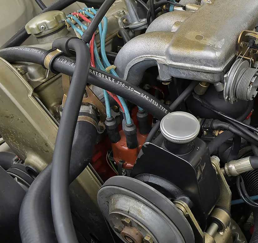 Distributor Part Numbers: 1976 USA: Volvo PN 463694, Bosch 0 237 002 003 or 0 237 002 007. 1977 Canada, Japan: Volvo PN 463694, Bosch 0 237 002 007. 1978 California, Canada, Japan: Volvo PN 1266466, Bosch 0 237 003 009. 1979 California, Japan (Canada -1980): Volvo PN 1276403, Bosch 0 237 002 039. 1980-81 USA (Canada 1981-82): Volvo PN 1276403, Bosch 0 237 002 039. 1981-85 USA: Volvo PN 1276703, Bosch 0 237 003 024 for 240 Turbo B21FT. Other Volvo distributor PN 1266904, Bosch 0 237 002 038 (unk. years or applications). Breakerless distributors will have vacuum diaphragm canisters. Distributor cap PN 243797. Rotor PN 243903. 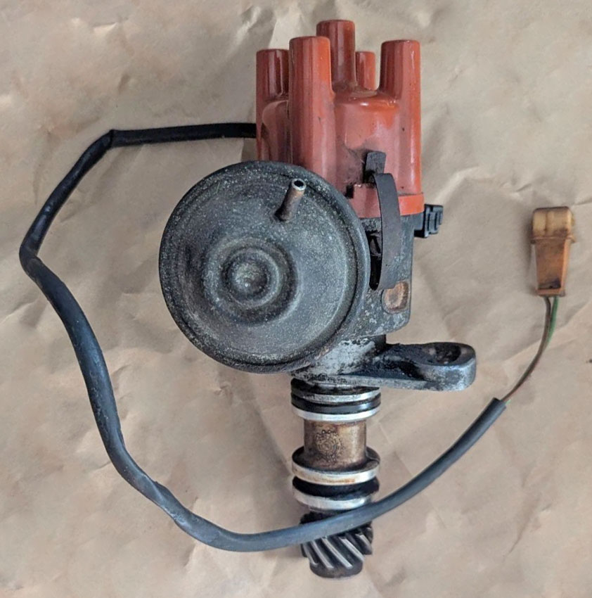 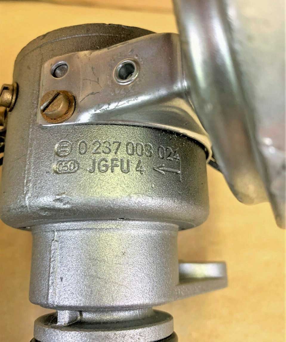 Distributor Impulse Sender: PN 1276619, Bosch 1 237 031 123. 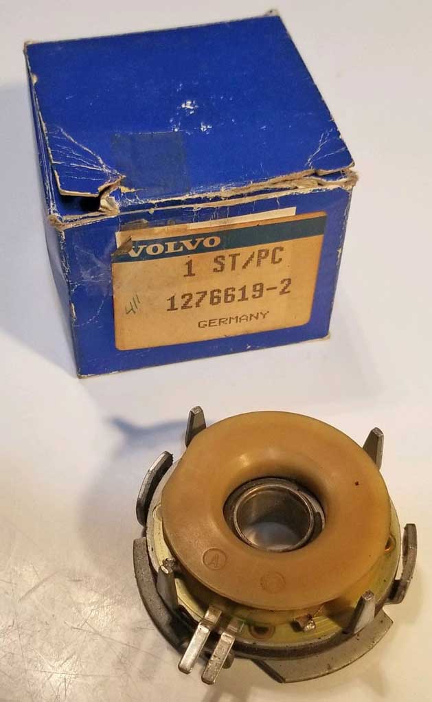 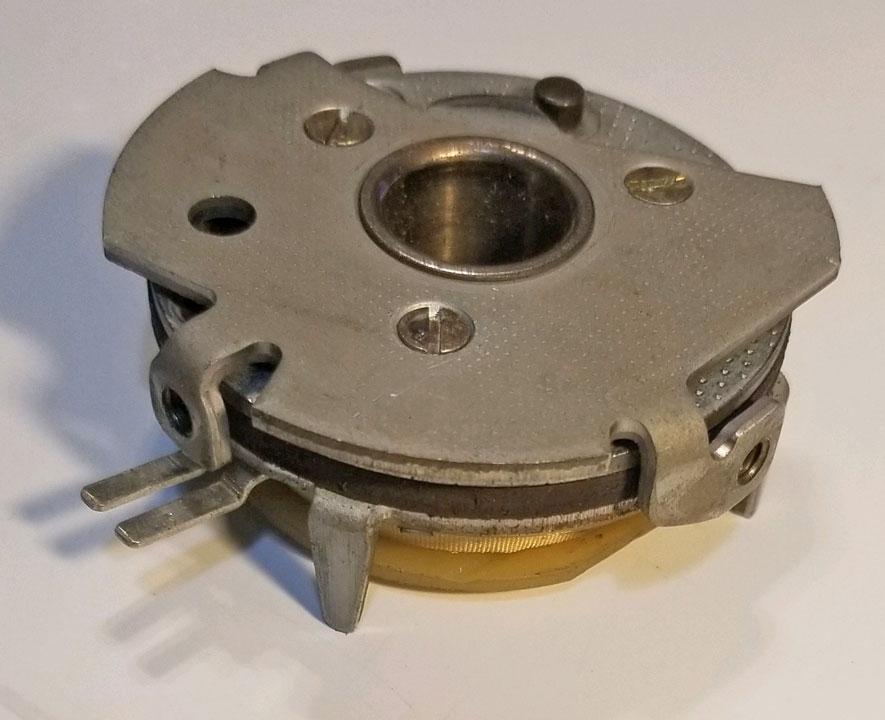 Ignition Control Unit Part Numbers: Bosch 0 227 100 018 for all 1975-84. And also Bosch 0 227 100 005 for unknown year 240. 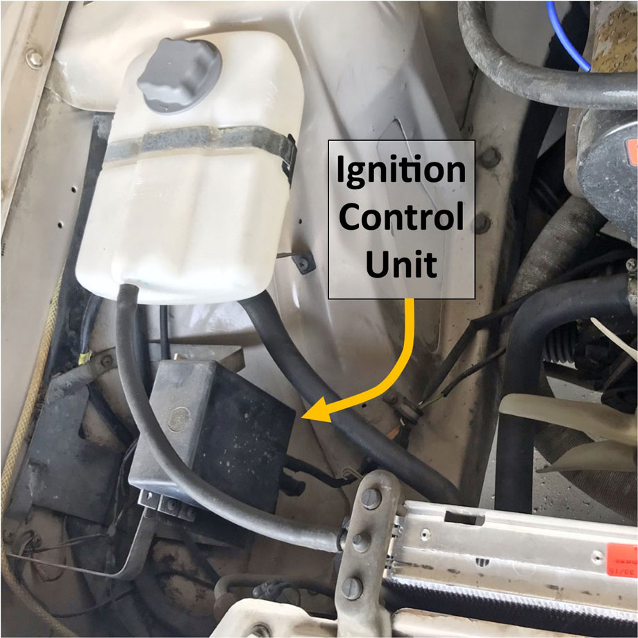 .") The type of coil used in this Bosch Breakerless System was designed for and required a LOWER voltage when running. Bosch Coil, Volvo PN 1219230, Bosch PN 0 221 122 006. 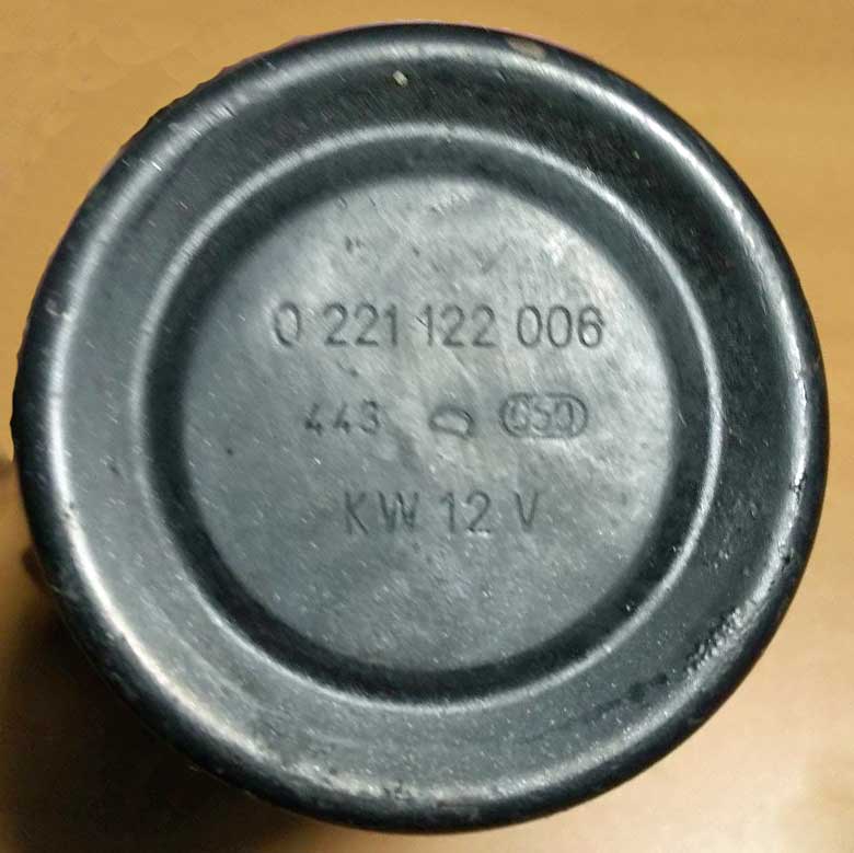 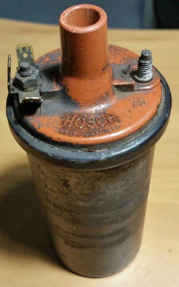
A 240 with Breakerless Ignition uses a BALLAST RESISTOR in the Coil Power Circuit, which is fully explained in the Ballast Resistor info below. Detailed FUNCTION DIAGRAMS for this ignition can be found in my page. 2. Computer Controlled Ignitions (Chrysler designed) These Computer Controlled Ignitions began with 1981 240s equipped with Bosch K-Jetronic mechanical fuel injection (engine designation: B21F MPG). This Chrysler designed ignition was carried over to the 1982, '83 and '84 240 non-turbo. The 1983-84 240 with a B23F changed to Bosch LH 2.0 and LH 2.1 electronic fuel injection. This ignition can be quickly recognized by a larger ignition control unit mounted under the hood on the right inner fender. 1981 to 1982 cars would have a distributor with a WHITE distributor cap. For 1983 these cars might have a WHITE distributor cap or a RED distributor cap, but the ignition internal design and the control units were the same (although parts numbers did change). For 1984, most 240 with the B23F would have a RED distributor cap. Distributor Part Number (WHITE Distributor CAP): 1981-82 240 with B21F and some 1983 240 with B23F: Volvo PN 1306059. Distributor cap PN 1306210. Rotor PN 1332125. 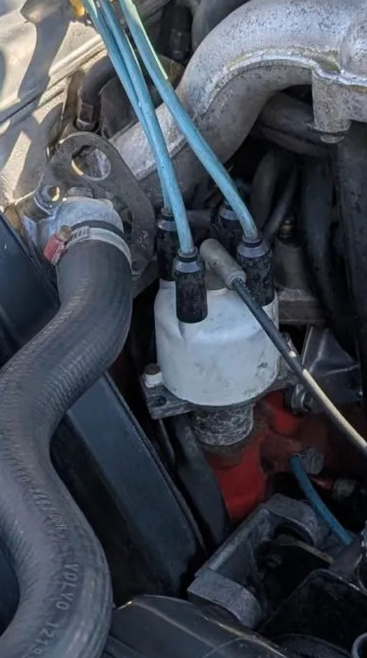  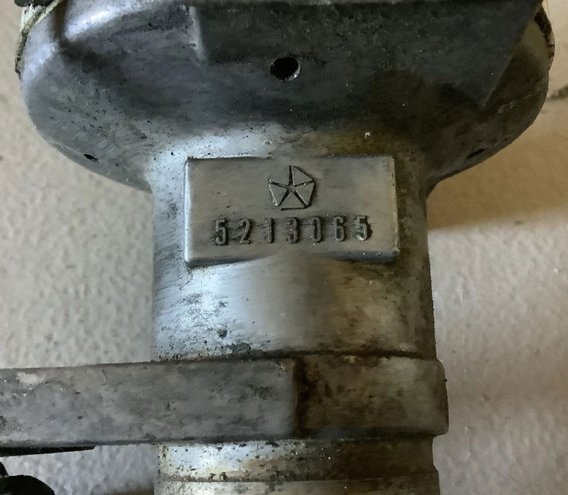 Hall generator breaker plate for WHITE cap distributor (with ROUND CONNECTOR): Volvo PN 1332207. 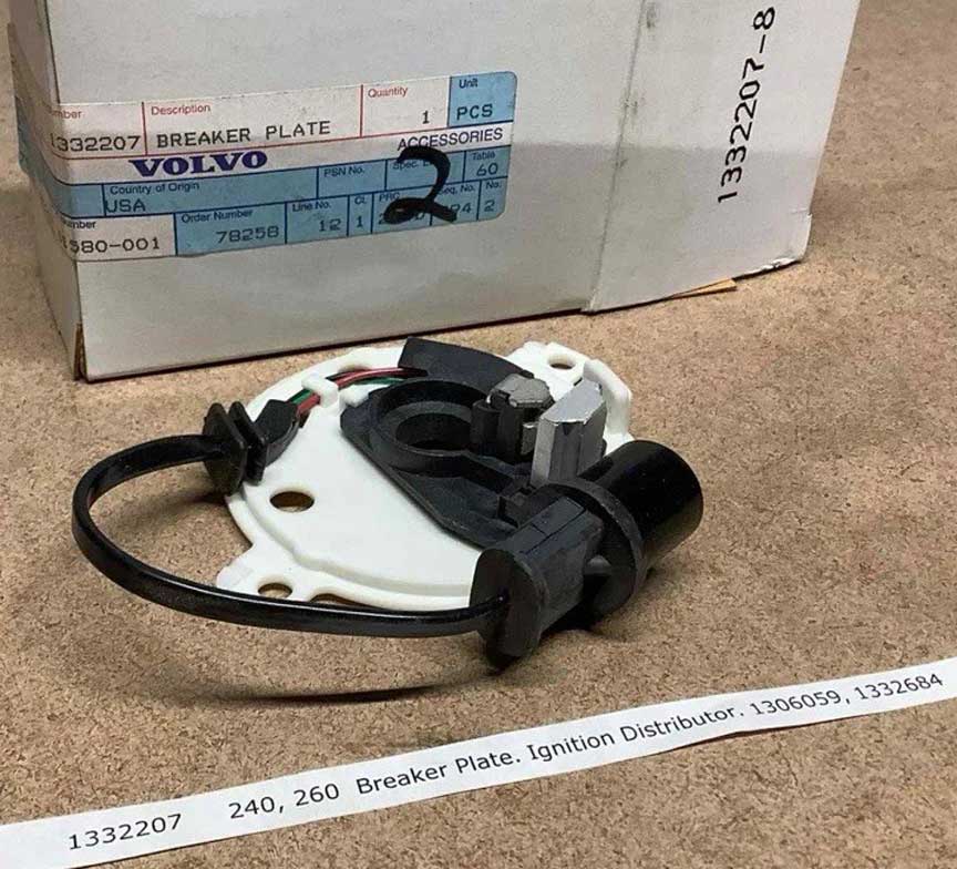 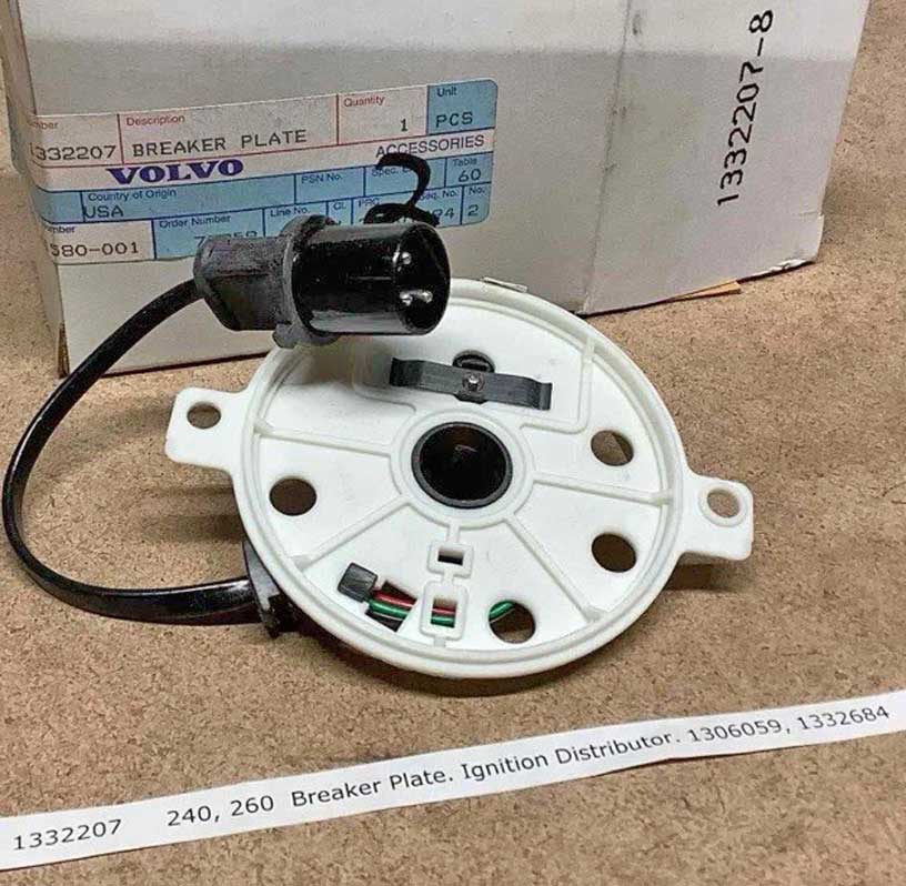 Distributor Part Numbers (with RED Distributor CAP): 1983 240 with B23F: Volvo PN 1332684, Bosch 0 237 032 002 (Note some 1983 models got the white cap distributor above). 1984 240 with B23F: Volvo PN 1336737, Bosch number 0 237 506 003. Distributor cap PN 243797. Rotor PN 1336240. This distributor looks similar to the below 1985-88 type. Note that the pictured distributor below has a RECTANGULAR 3-pole connector. 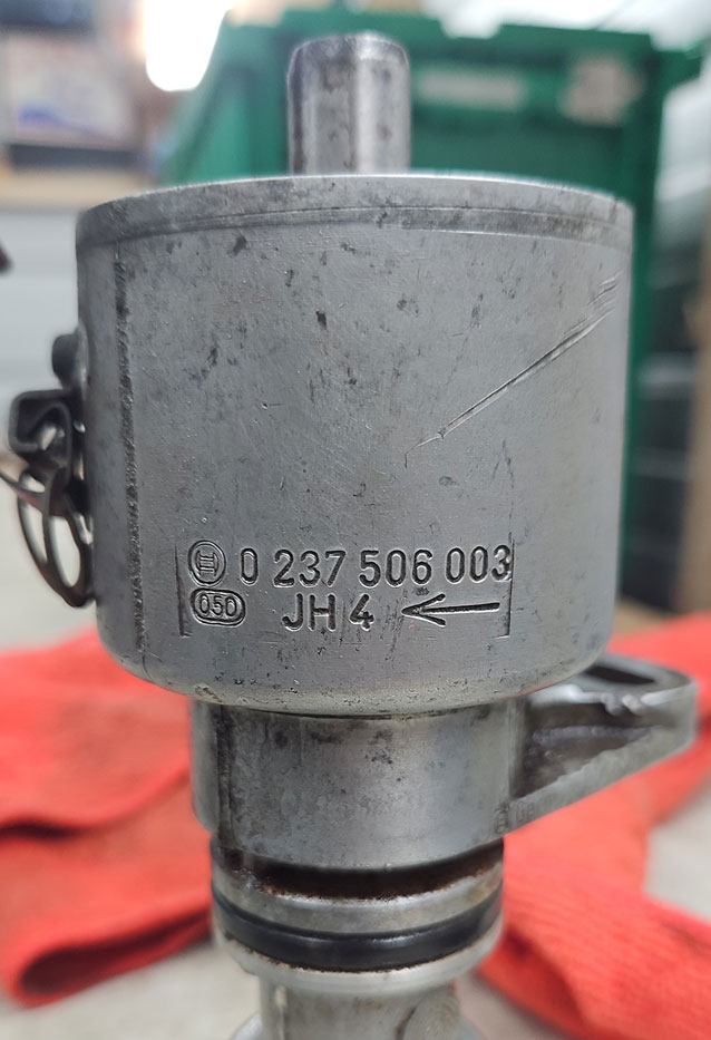 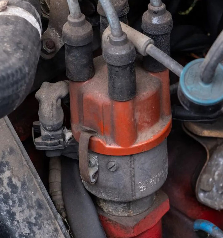 There are some cases where a 1983 RED cap distributor came with a ROUND 3-pole connector identical to the connector on the above white cap distributor. So far this distributor has been identified as being marked Bosch 0 237 032 001. 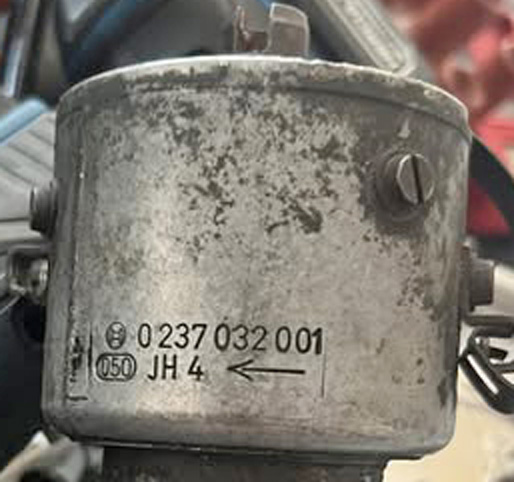 These distributors have a centrifugal advance mechanism inside, but no vacuum diaphragm. This distributor does not have a vacuum advance diaphragm. For this system, the Ignition Control Unit will have vacuum diaphragm. 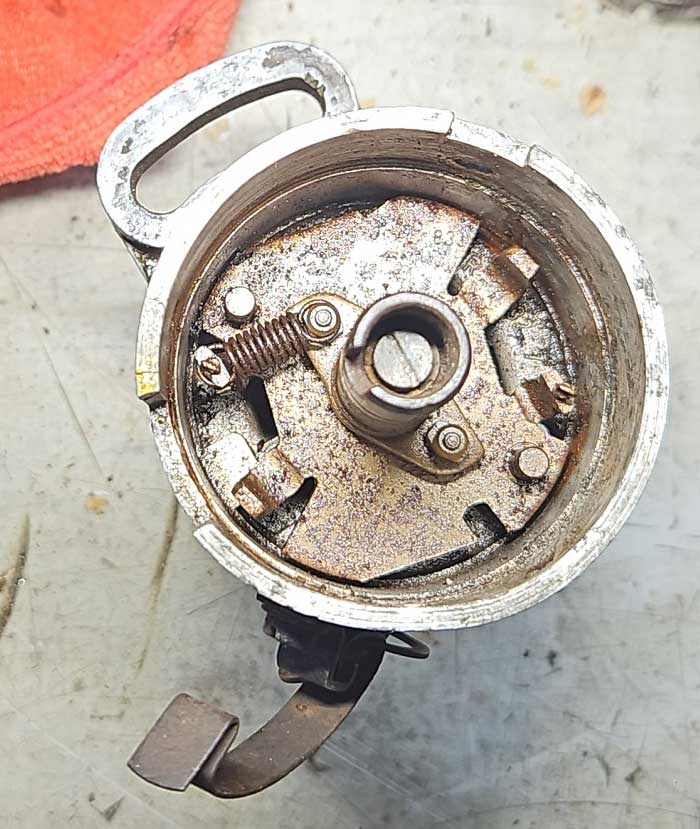 Distributor Hall Sensor with RECTANGULAR connector: Volvo PN 1346803, Bosch 1 237 031 166. (Reportedly this also fits the early 1985 B230F distributor Volvo PN 1332587, Bosch 0 237 506 001). More information see HALL SENSOR NOTES below. 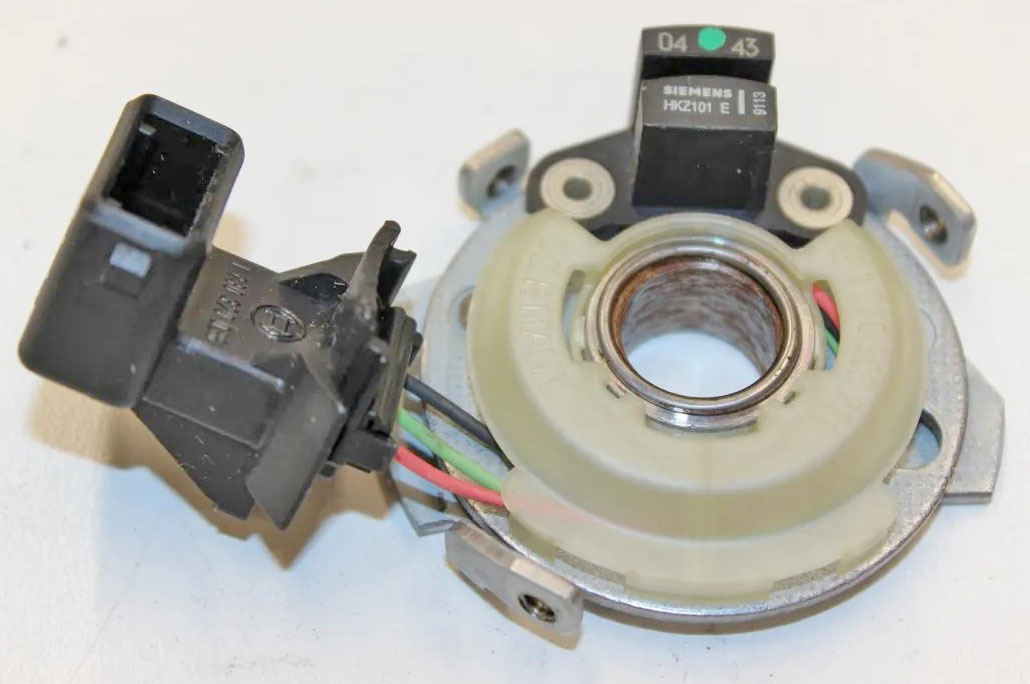 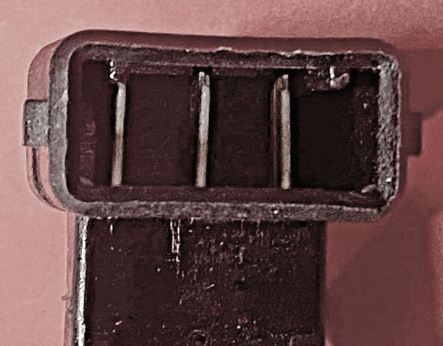 Distributor Hall Sensor with ROUND connector: Volvo PN 1336432, Bosch 1 230 500 221. Came in the RED cap distributor marked Bosch 0 237 032 001. More information see HALL SENSOR NOTES below. 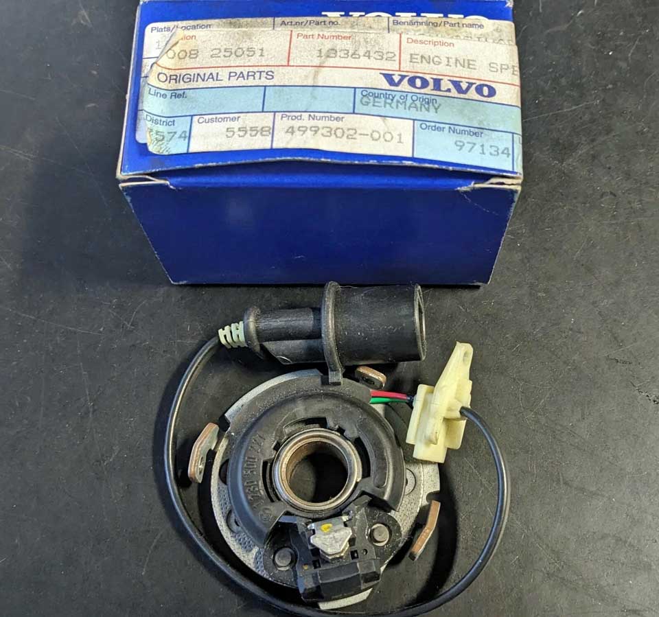 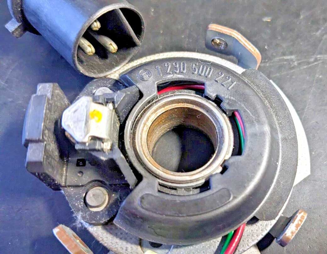 Ignition Control Unit Part Numbers: 1982 240: Volvo PN 1317873. 1981-84 240: Volvo PN 1317295. 1984 240: Volvo PN 1346105. These ICUs all came with vacuum advance diaphragm canisters. .")
The type of coil used in this system with a WHITE or RED distributor cap is below. Bosch 12v Coil Volvo PN 1306058, 1336137, Bosch 0 221 122 345. 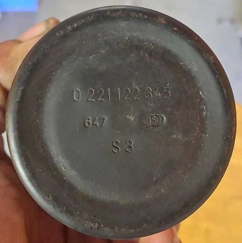 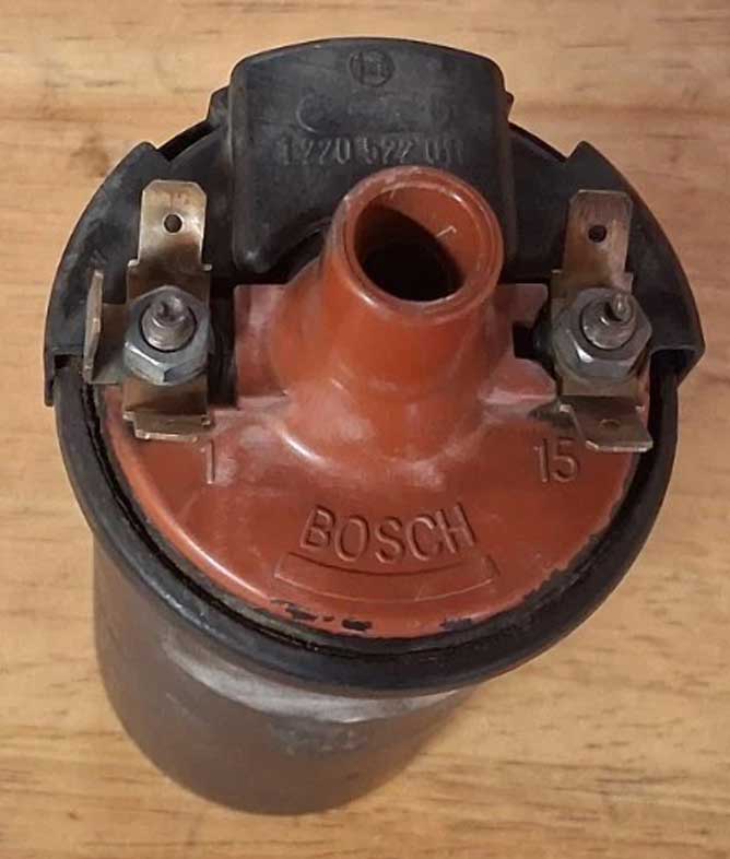 Detailed FUNCTION DIAGRAMS for these systems may also be found in my pages. 3. 1985-88 Computer Controlled Ignitions (Chrysler designed) Beginning in 1985 for the introduction of the new B230F equipped 240, a newer version of the above Computer Controlled Ignition was introduced. This ignition was used in the 240 through 1988. These 1985-88 240s were all equipped with Bosch LH 2.2 fuel injection. This ignition could be also recognized by the large ignition control unit (ICU) mounted on the right inner fender. This ICU came with a vacuum diaphragm, similar to earlier ICUs. The distributor cap was always RED for all 1985-88 240s with this ignition. Distributor Part Numbers: Most 1985-88 240: Volvo PN 1332587 (early Alter 1), or 1367382 (Alter 2), Bosch PN found on Alter 2: 0 237 520 004. Distributor cap Volvo PN 243797. Rotor PN 1389425, or 13894258. The 1985-88 distributor looks similar to the 1989-93 type, except this one has an electrical connection and a Hall Sensor inside. The 1989-93 type does not. There is an early 1985 B230F distributor below with with Bosch PN 0 237 506 001 (this is probably the early Alter 1 Volvo PN 1332587 mentioned above). 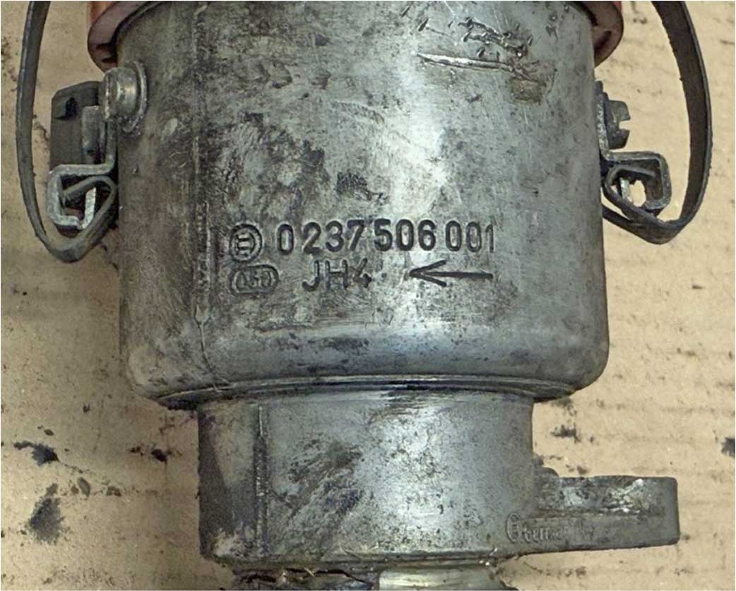 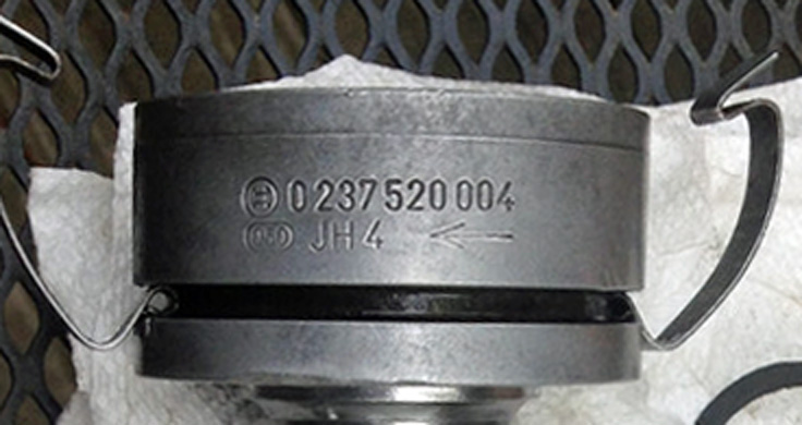 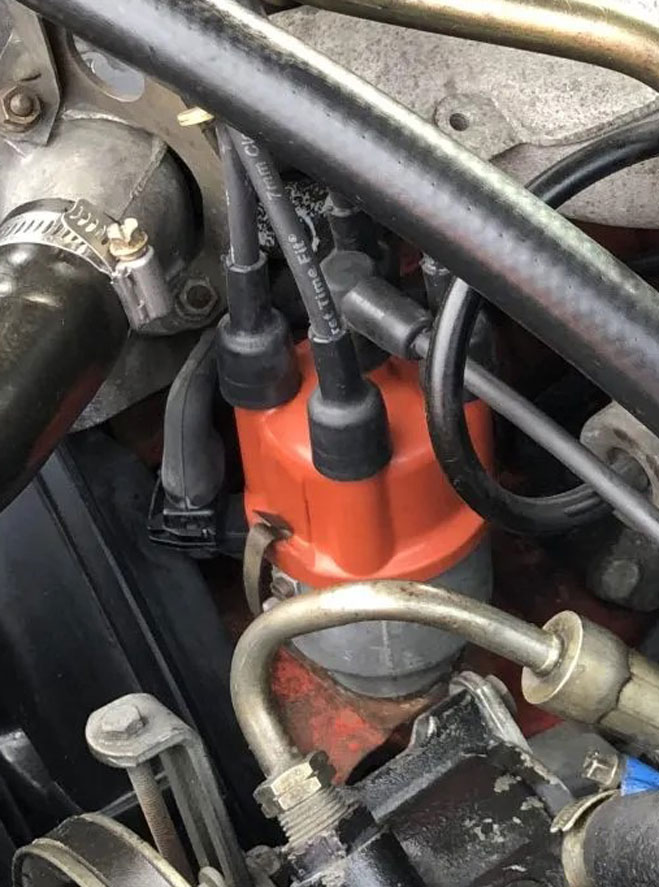 Distributor Hall Sensor Volvo PN 1346803, Bosch 1 237 031 166. For early B230F distributor with Bosch PN 0 237 506 001. (Reportedly also fits 1984 B23F distributor Volvo PN 1336737, Bosch 0 237 506 003). More Hall Sensor information see HALL SENSOR NOTES below. Distributor Hall Sensor Volvo PN 1389424, Bosch 1 237 031 292. It should be noted this sensor fits distributor Volvo PN 1367382, marked Bosch 0 237 520 004. It will not fit an early 1985 B230F distributor with Bosch PN 0 237 506 001. More Hall Sensor information see HALL SENSOR NOTES below. 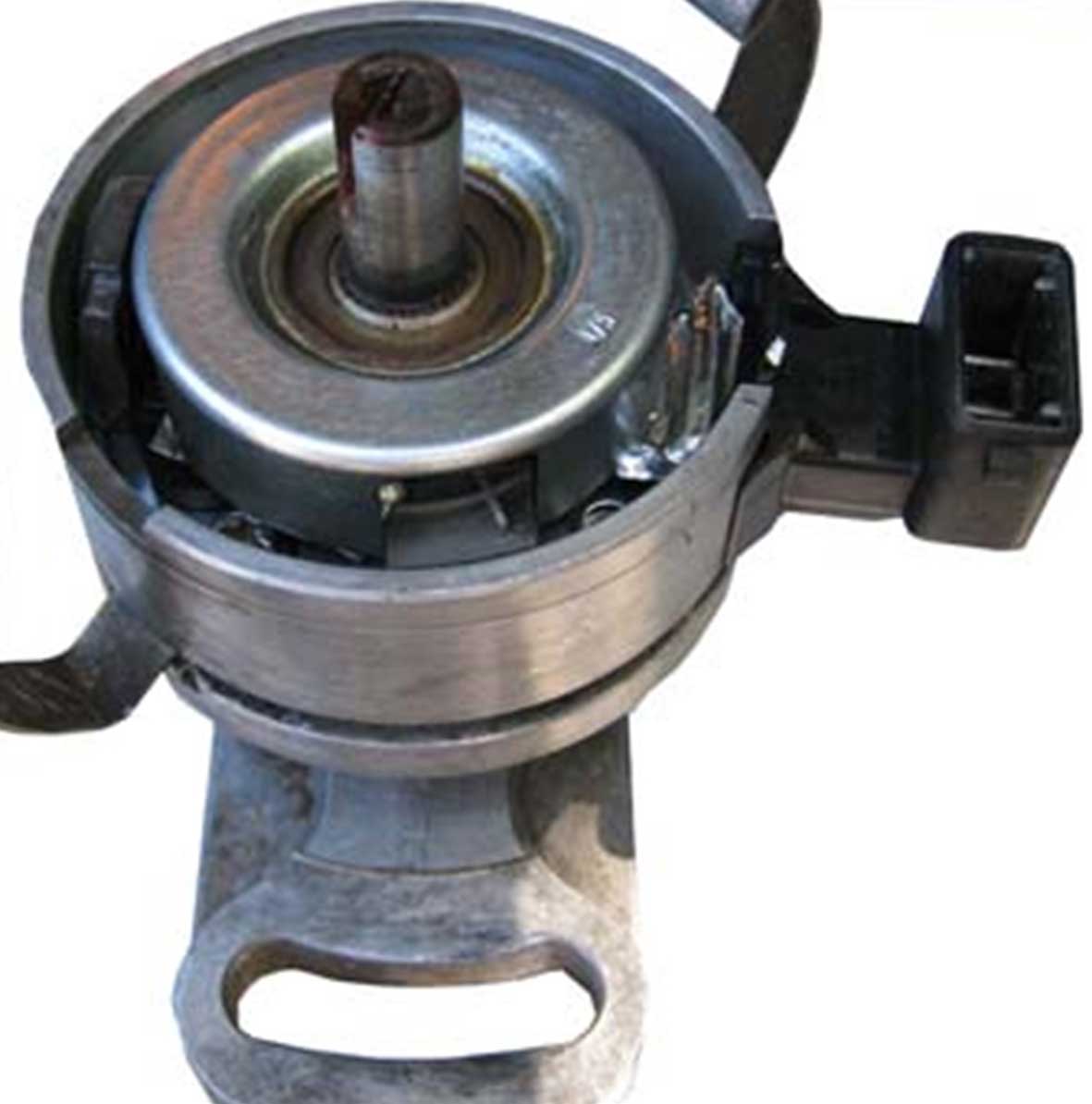 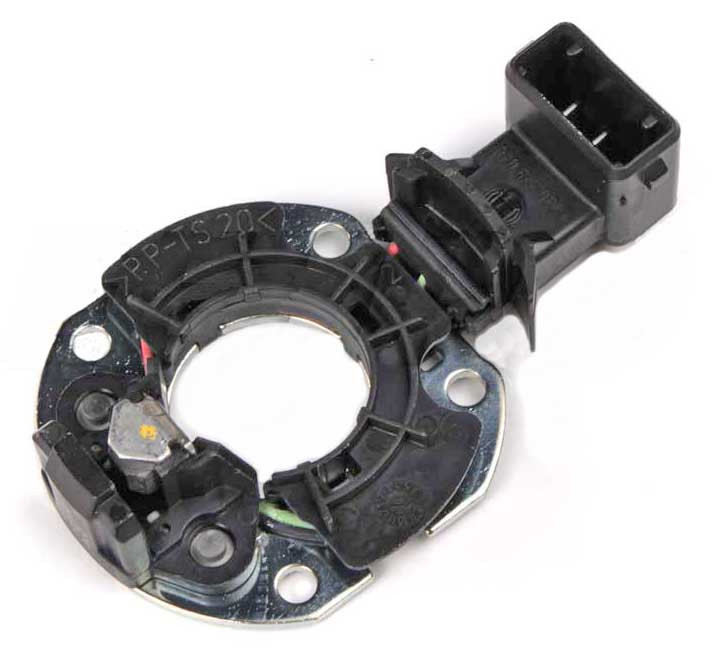 Ignition Control Unit Part Numbers: Volvo PN 1346107 found in 1985, 1986, 1987 (compatible with all 1985-88). Volvo PN 3517641 found in 1986, 1988 (compatible with all 1985-88). Volvo PN 1357308 found in 1988 (compatible with all 1985-88). 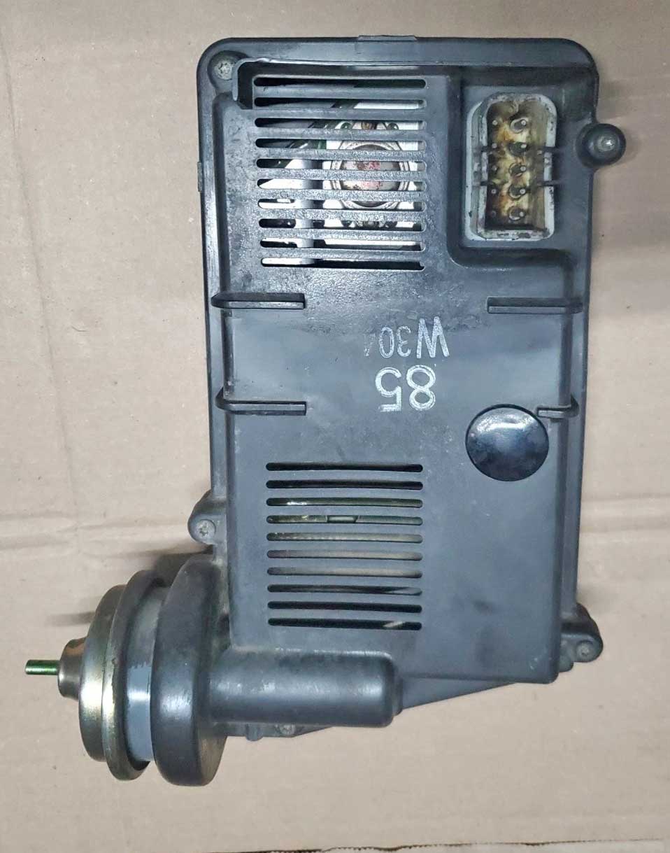 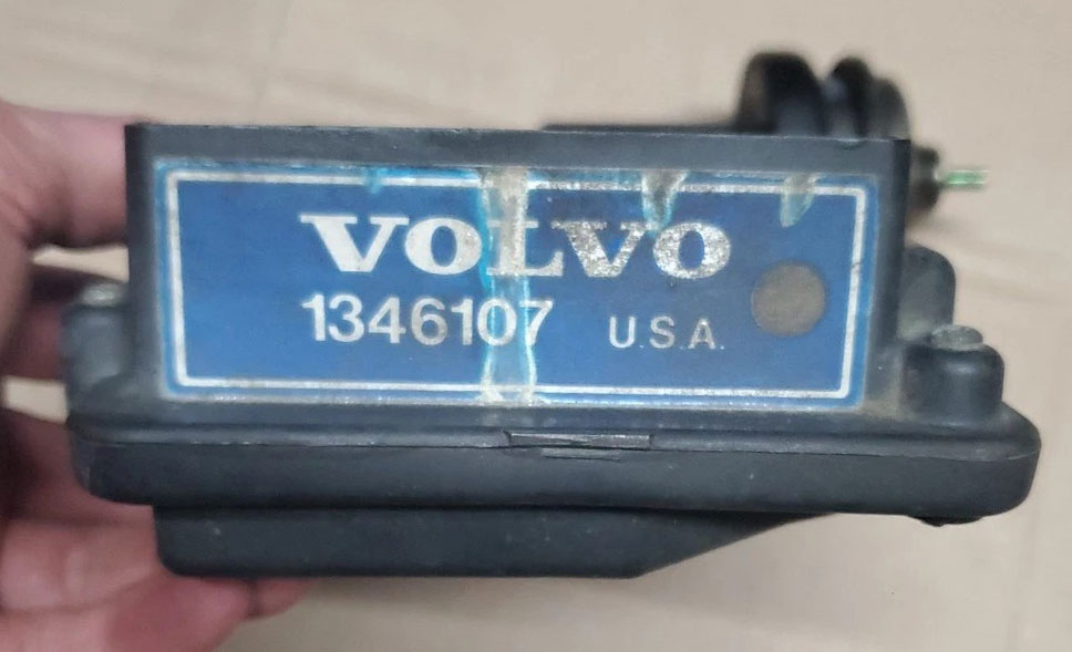 The type of coil used in this Bosch System is below. Bosch 12v Coil Volvo PN 1336137, Bosch 0 221 118 351. 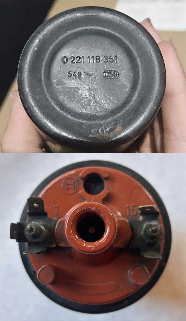 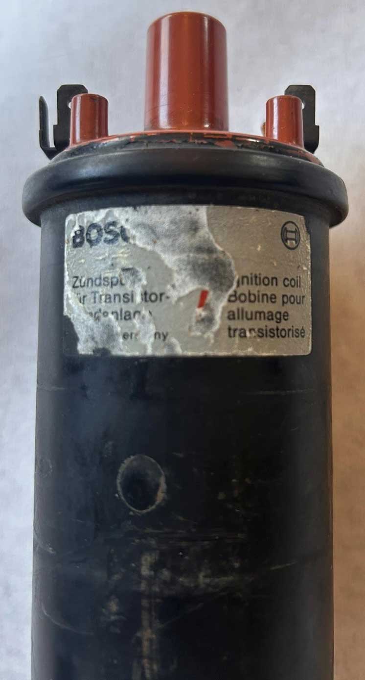 Detailed FUNCTION DIAGRAMS for these systems may also be found in my pages. 4. 1989-93 240 EZK Ignition (Bosch EZ116K) With the introduction of Bosch LH 2.4 fuel injection, the 1989 to 1993 240 received the new Bosch EZK (EZ116K) ignition. This was was very similar to EZK ignitions used in 700 and 900 models. The ignition control unit (ICU) for the 1989-93 240 was found under the right side dash near the Bosch EFI control unit. No ignition module is found under the hood in a 1989-93 240. The distributor has a RED distributor cap. Distributor Part Numbers: 1989-93 240: Volvo PN 1367468, BOSCH 0 237 502 002, 0 237 523 003. Cap PN 243797. Rotor PN 1389425, 13894258. 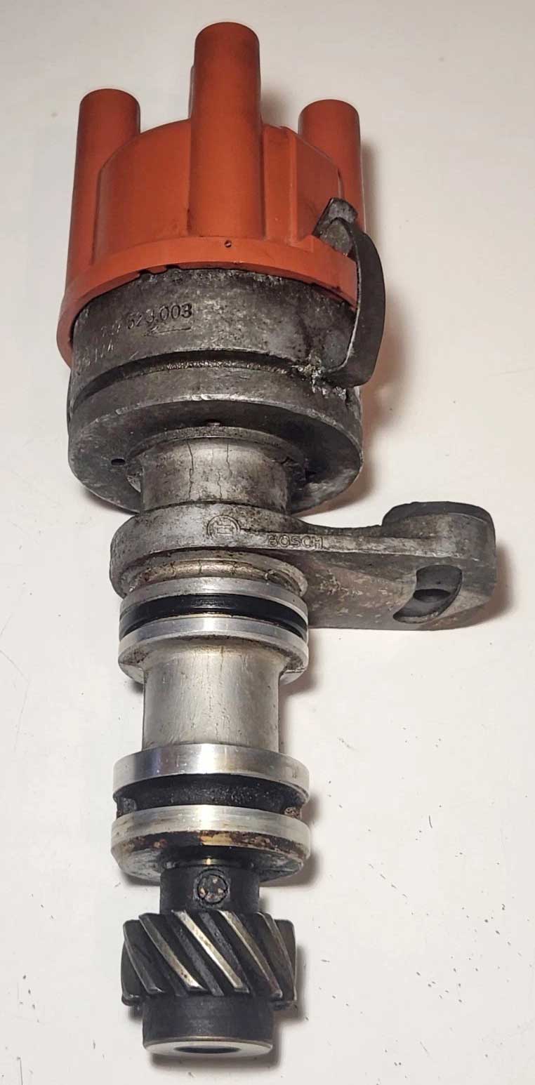 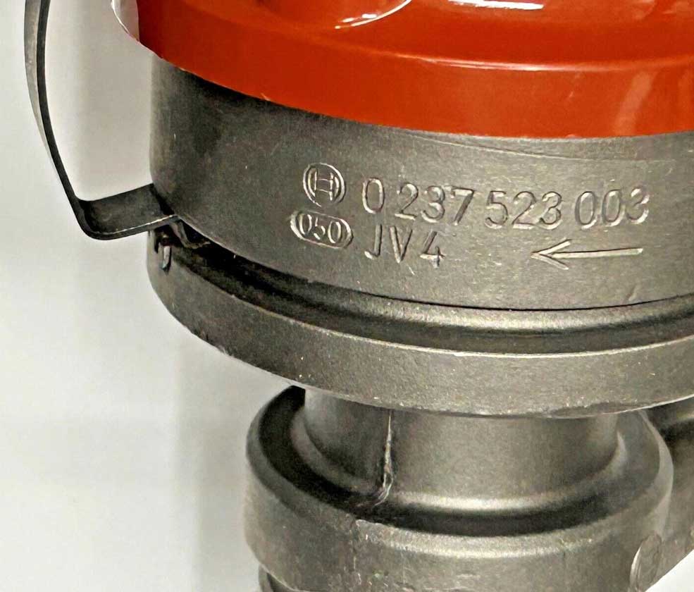 This distributor looks similar to the above 1985-88 240 type, except this does not have an electrical connector or a hall sensor inside. 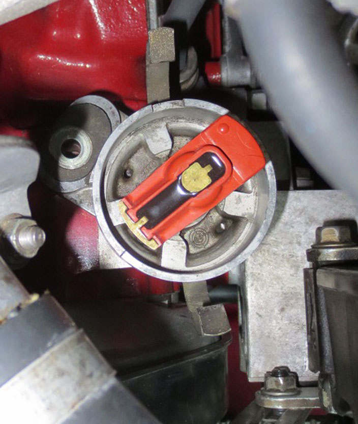 Ignition Control Unit Part Numbers (Bosch EZ116K): This ICU was found under the passenger side dash in a 240. Volvo PN 3501688, Bosch 0 227 400 140 (B230F with EGR designated California). Volvo PN 3517402, Bosch 0 227 400 146 (B230F designated USA, Federal). Volvo PN 3517855, Bosch 0 227 400 162 (with EGR). Volvo PN 3531325, Bosch 0 227 400 169 (B200E, B200F, B230E, B230F, B230G, B230K). Volvo PN 3531830, Bosch 0 227 400 176 (B200F, B200G). Volvo PN 6842495, Bosch 0 227 400 209 ("GOLD box") (with EGR). 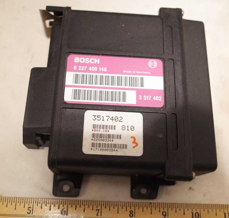 The type of coil used in this Bosch System is below. Bosch 12v Coil, Volvo PN 1317810, 1317815, 9428228, Bosch PN 0 221 122 334. 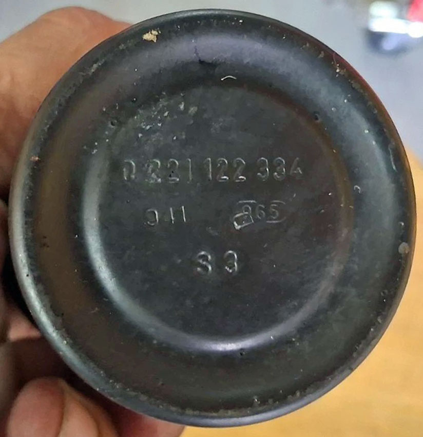 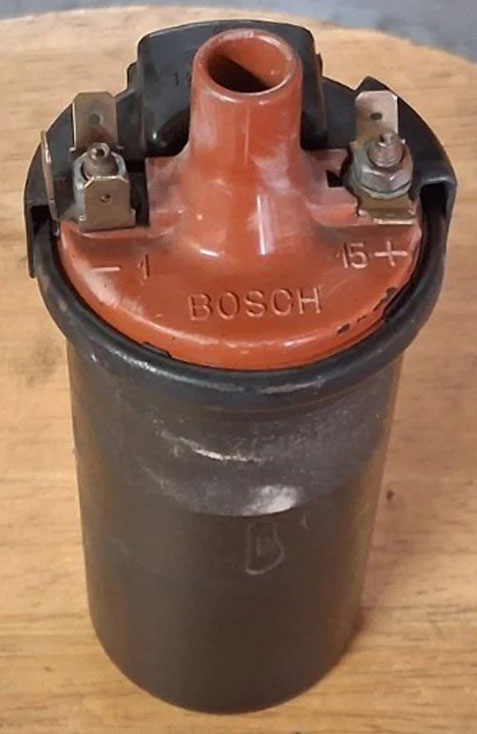 Detailed FUNCTION DIAGRAMS for these systems may also be found in my harness pages. HALL SENSOR NOTES This info is related to the 1983-84 240 Ignition Hall Sensor and the 1985-88 240 Ignition Hall Sensor. The below TB link discusses info related to a creating DIY Hall Sensor setup using a universal Hall Sensor to replace the original one in the distributor. https://turbobricks.com/index.php?threads/source-for-bosch-lh2-2-distributor-hall-effect-connector-pins.334828/ Link referenced in above thread: https://www.hallsensors.de/Hall-Vane.htm This discusses includes Hall Sensor CYHME301S as a compatible replacement for Hall Sensor HKZ101 originally used in a Volvo distributor. Technical reference for Sensor CYHME301S: https://www.cy-sensors.com/CYHME301S.pdf 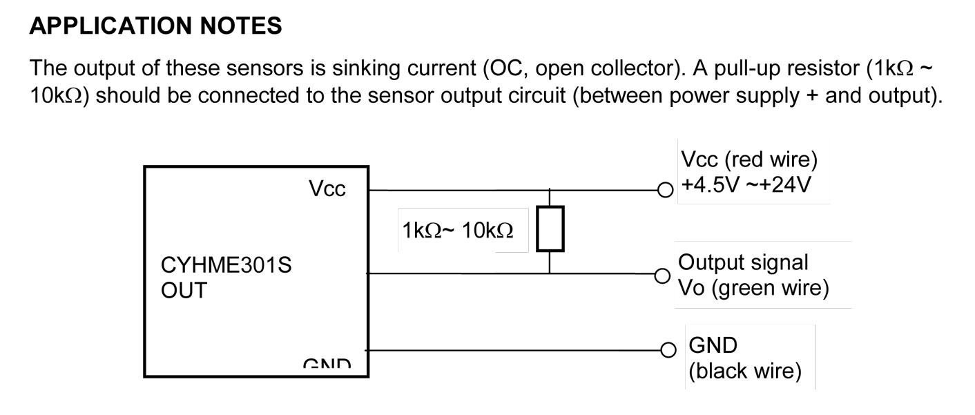 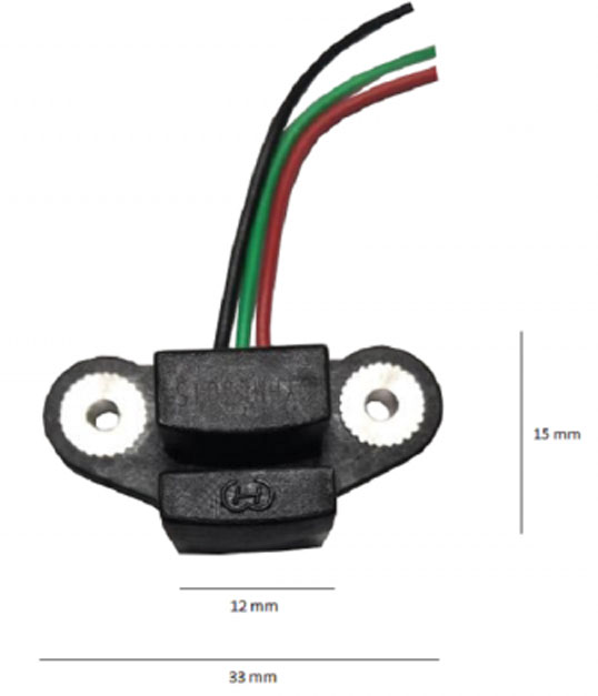 Replacement MALE 3-pole connector housing for 1983-88 Volvo 240 distributor displaying Bosch PN 0 237 506 003 or 0 237 520 004. Receptacle connector housing Volvo PN 1389492, Bosch 1 230 329 025. https://classicvolvorestoration.com/p/housing-housing 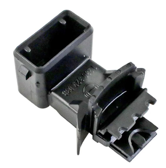 Replacement FEMALE 3-pole distributor harness connector plug housing to plug in to the above receptacle. https://www.prancingmoose.com/blackvinyl.html#1324582  Detailed Info: 240 Ignitions with a BALLAST RESISTOR connected to the coil circuit. Questions about ballast resistors will come up occasionally, so I thought I would detail what these were used for, what cars had them, and what coils were normally used with them or without them (yes, they used different coils). For any 240 equipped that came with a BOSCH BREAKERLESS IGNITION (with B21F, B21FT and some B23F), these cars were all equipped with a BALLAST RESISTOR. Volvo also began using Computer Controlled (Chrysler) ignitions beginning in 1981-82 (for some B21F versions, B21F-MPG), in 1983-84 (for B23F) and beginning in 1985 (for B230F). The Computer Controlled Ignition did NOT use a Ballast Resistor and the types of coils in these cars were a different design. More COIL INFO BELOW. BALLAST RESISTOR FUNCTION Volvo PN 1266014, Bosch PN 0227900010. The purpose of this ballast resistor was to reduce voltage to the coil from 12+ volts to about 9 volts during normal engine running. The bracket has '0,9' stamped into it indicating a 0.9 Ohms resistance setting. 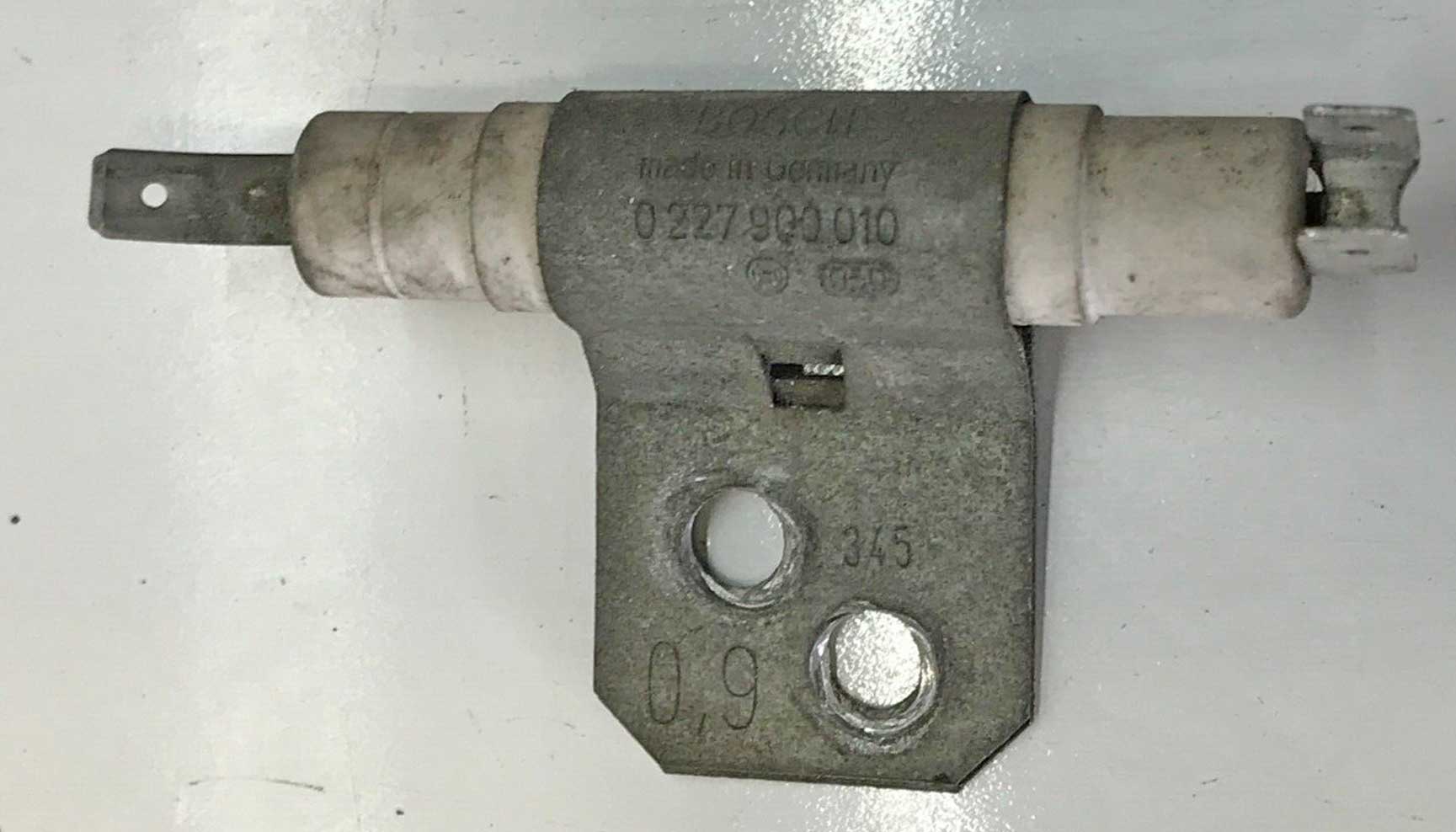 A car like this which uses a ballast resistor will have a special wire circuit that will bypass the resistor when the starter is engaged to promote a hotter spark when starting, but then revert back to the lower coil voltage during normal running. Reportedly if you were to allow a 9 volt coil to run with a full 12+volts constantly, the coil could fail prematurely from over-heating or possibly the extra voltage could damage the ignition amplifier or control unit. The type of coil used in this Bosch Breakerless System was designed for and required the LOWER voltage when running. Bosch Coil, Volvo PN 1219230, Bosch PN 0 221 122 006. BALLAST RESISTOR THEORY: Historically an ignition system which didn’t use a ballast resistor seemed to run fine using a 12 volt coil with 12 volt battery power. It was found that extra voltage to the coil during starting would help overcome poor cold starts, but with a 12 volt system, no extra voltage was available. One reason that was discovered is that the starter draws a lot of current during starts and this further reduced the available voltage to the ignition during starting. To correct this, some ignition systems were designed to use a 9 volt coil instead of a 12 volt coil. If a coil was designed to provide sufficient output at only 9 volts during normal running, then it could temporarily get an extra boost when fed 12 volts during starts, which would offer a stronger spark, with less potential energy loss in the ignition when spinning the starter. 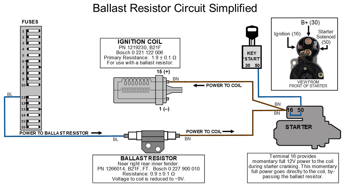
BALLAST RESISTOR LOCATION in a 240: The ballast resistor in a 240 can usually be found located on the right inner fender, back near the firewall, below and not very far from the wiper motor. 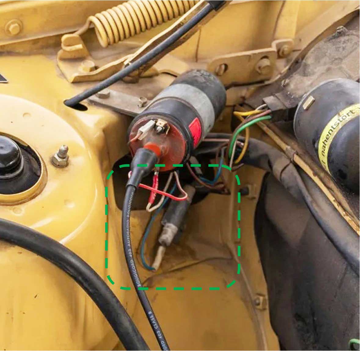 MEASURING THE RESISTANCE OF A BALLAST RESISTOR This one pictured is Volvo PN 1266014, Bosch 0 227 900 010, which should measure about 0.9 Ω (0.9 Ohms).  Above image is from TP30432/1 Ignitions 1975-84 page 38 for cars with Breakerless Ignition Systems. This diagram below is a page from my FUNCTION DIAGRAMS for the 240 with B21F. This will give you a good look at the way power is routed from the fuse panel, then through the starter and ballast resistor before it reaches the ignition coil. Breakerless Ignition and Ballast Resistor Diagram Detail. More pin function diagrams found at https://www.240turbo.com/PinFunction1980-82-240.html  BOSCH COILS Most ignition coils will have Positive and Negative marked with PLUS and MINUS. Bosch coils are sometimes not marked this way. Bosch coils will have terminal numbers 1 or 15. Sometimes they'll have these numbers along with PLUS or MINUS symbols. Terminal 1 is always NEGATIVE and Terminal 15 is always POSITIVE. 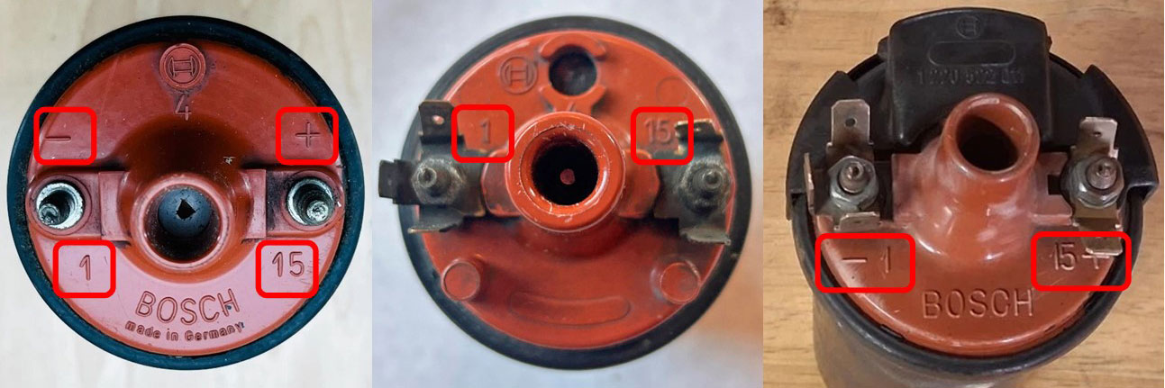 BOSCH COMPONENT TERMINAL NUMBER DESIGNATIONS If you've ever wondered where the coil or relay and other electrical component terminal numbers come from, they were standardized by Bosch many years ago. A list of those terminal numbers and their meanings can be found at the following link for an except from the Bosch Automotive Handbook: https://dastern.torque.net/techdocs/boschterm.html MEASURING THE RESISTANCE OF A COIL IF YOU'RE REPLACING A COIL, it's important to make sure your 240 is getting the proper type. If there's a question about the resistance of a coil , you can measure the resistance with an Ohm meter set to OHMS for primary resistance testing or kOHMS (kilo-ohms) for secondary resistance testing. All terminals must be disconnected from wires before testing. If you're unsure how to do this measurement, do a search in YouTube: or try here https://www.youtube.com/shorts/tGeZQUHzGrg or here https://www.youtube.com/watch?v=g2HT1oGl990.  Coil Volvo PN 1219230, Bosch 0 221 122 006 Early 240 B21F or FT, with K-Jetronic, Breakerless Electronic Ignition, used WITH an external ballast resistor. PRIMARY Resistance: 1.8 to 2.0 Ω. SECONDARY Resistance: 9.5 ± 1.5 kΩ (kiloohms). Coil Volvo PN 1306058, 1336137, Bosch 0 221 122 345 1983-84 240 B23F LH 2.0, Computer Controlled (Chrysler) Ignition, used WITHOUT an external ballast resistor. PRIMARY Resistance: 1.1 to 1.3 Ω. SECONDARY Resistance: 9.9 to 12.1 kΩ (kiloohms). Coil Volvo PN 1336137, Bosch 0 221 118 351 1985-88 240 B230F LH 2.2, Computer Controlled (Chrysler) Ignition, used WITHOUT an external ballast resistor. PRIMARY Resistance: 1.1 to 1.3 Ω. SECONDARY Resistance: 9.9 to 12.1 kΩ (kiloohms). Coil Volvo PN 1317810, 1317815, 9428228, Bosch 0 221 122 334 1989-93 240 B230F LH 2.4, EZ116K, used WITHOUT an external ballast resistor. PRIMARY Resistance: 0.6 to 0.8 Ω. SECONDARY Resistance: 6.9 to 8.5 kΩ (kiloohms). 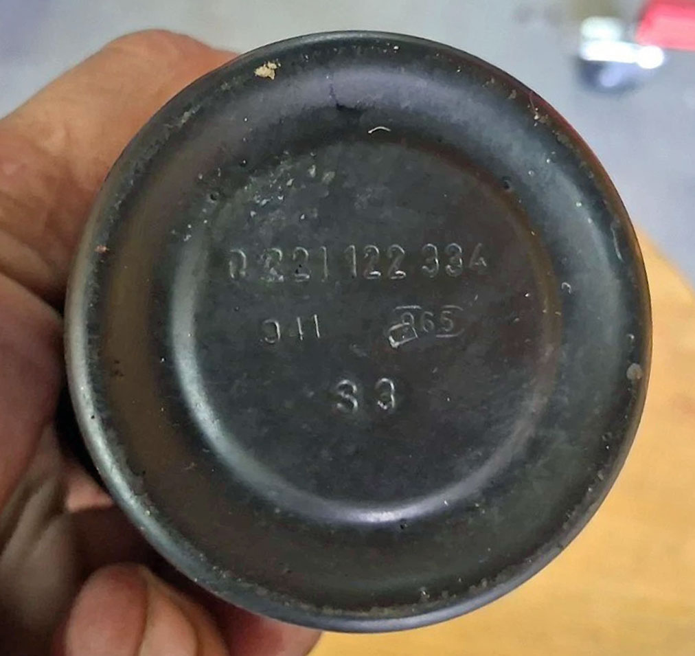 Also this article helps explain some on this subject: burtonpower.com/ignition-systems There is CONFUSION when trying to understand Volvo Primary Resistance measurements compared to YOUR coil expectations. Coupled with posts I see about people installing aftermarket coils with primary resistance FAR from a factory setting. There are many articles and videos discussing how the rest of the world determines if an ignition coil is an INTERNAL resistor type or EXTERNAL resistor type. My definition of an INTERNAL resistor type is any coil that does not use an EXTERNAL resistor. If you research this, you'll find that most INTERNAL resistor coils out there are said to measure about 3 Ohms primary resistance and most EXTERNAL resistor coils are said to measure about 1 to 2 Ohms. This last measurement is pretty aligned compared to the 1.9 Ohms measurement of the above Breakerless Ignition coil. And there are references that say if you add the resistance value of the ballast resistor (0.9 Ohms) to the primary resistance of this coil (1.9 Ohms), then you have a coil with 2.8 Ohms. This makes sense. But if an INTERNAL resistor coil should be about 3 Ohms as the rest of the world says, how does that reconcile with the Volvo primary resistance measurements above of 1.1 to 1.3 Ohms for a 1985-88 240 or 0.6 to 0.8 Ohms for a 1989-93? Also for clarification, this coil image BELOW is a Bosch 0 221 122 334 for the 1989-93 240. The black device on the top (with PN 1 220 522 011) is presumed to be an added ballast resistor, which apparently was added by Bosch to create a coil with a specific resistance setting. In my observation, Bosch coils with this black resistor can be found in the majority of Volvo 240s from 1983 and later. If this black device is a resistor, In my mind I could define this coil as an INTERNAL resistor type, however when measuring primary resistance, it will not match the 3 Ohm setting the rest of the world expects from an INTERNAL resistor coil. This makes me curious of the resistance value of that black device and of the coil with that device removed. If you can offer help in this area, I'd appreciate an email. 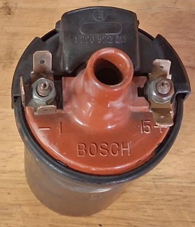 Also there are lots of people who replace their original Volvo coil with something other type or non-Bosch brand, often without ever knowing or checking to see if the new coil is compatible. The confusion above doesn't help. I have seen posts with people installing aftermarket INTERNAL resistor coils with 3 Ohms resistance in their later 240s. I can't really say how well that's working, so it's something I'm curious about, but I probably wouldn't try in my own car. One potential error could be installing an EXTERNAL resistor coil on a car that doesn't have an external ballast resistor. As mentioned previously, this could potentially overheat and damage the coil or maybe the ignition control unit. Or someone installs an INTERNAL resistor coil on a car with a ballast resistor. This could potentially end up with a coil with TOO MUCH RESISTANCE and that could result in a weak spark. So it seems to be fairly important to try to get a decent match. |
| IGNITION TIMING |
This
section will begin with BASIC Volvo ignition timing stuff and then slowing introduce more advanced information. If you're
a novice in ignition timing, I
recommend that you read this beginning from HERE and try to absorb it one section at a
time (don't skip around much). I guarantee you'll learn some things about Volvo ignition timing. If you're already advanced
in this subject, I think you'll still learn a few things.
This image below came from a post in TB: turbobricks.com/curve-b21ft-distributor.378203/.
It offers a good basic explanation of the timing curves in a B21FT ignition distributor.  An example below: This image offers a good example of one important aspect of the basic ignition timing advance, which is the relationship between RPM and Degrees of Ignition Advance. This map is also made for a Volvo B21FT (1981-85 240 Turbo). I altered the below map to make it more simple for this subject. It's altered to only show RPM and degrees of ignition timing BTDC (Before Top Dead Center). It does NOT show static base timing at idle or vacuum/boost timing adjustments. I'll discuss that in more detail elsewhere. This map shows the TIMING ADVANCE this distributor will provide using the centrifugal advance mechanism only. If you need to know, the base timing at idle for a B21FT is typically 12º BTDC (which was not added here). 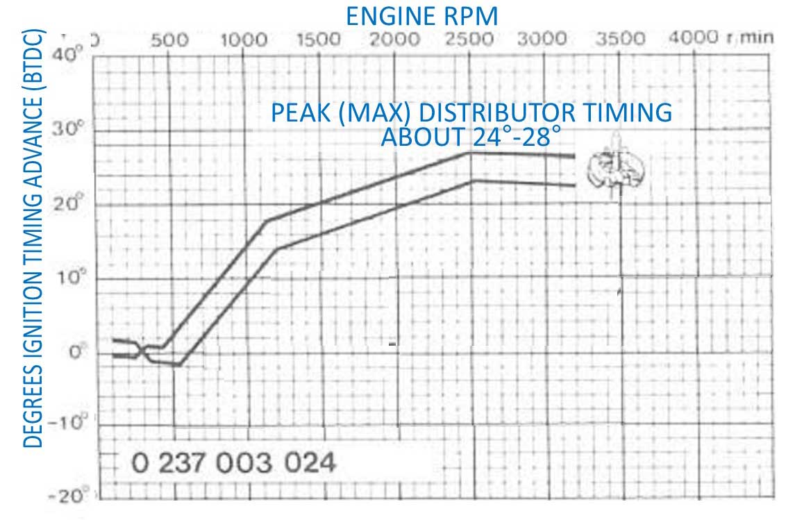 ABOVE: Volvo Ignition System Manual TP30432 pg 16. To keep this simple for now, this map does not take into account variable changes in engine manifold VACUUM or BOOST. The factory B21FT ignition system will compensate for engine vacuum and boost changes, creating small adjustments in the timing map. Those are designed to achieve good performance with regard to power, gas mileage, emissions and also safety from too much timing advance during boost (or over-boost). More info about this will be explained later. This B21FT timing ramp is generated by a centrifugal (mechanical) advance mechanism inside the distributor. The reason why it's max is 24º-28º is because it's not precise enough to choose just one precise setting. Don't expect miracles from 1970s tech. Once it reaches the max advance of around 25º to 26º it will maintain that level max until redline or beyond. If the above timing map was laid out like a more modern timing map table (and nothing is added for base timing at idle), it would look like this table below.
But don't worry about the above info if it's confusing. If the B21FT timing map was laid out like a more modern map AND if I included 12º base timing at idle, it would look like this below. To achieve this, all I would need to do is to rotate the distributor +2º to get 12º at idle. But with that added +2º, now the other timing numbers have all increased by +2º.
So if mods are limited, what can you do with a Stock Engine? For those of you with factory systems that can't really be "tuned" easily, just about the only thing you COULD change without getting a custom ignition would be to alter the ignition timing at idle. So if, for example, your factory ignition timing at idle is 12º BTDC and your preset timing map is maxed out at 25º-26º, and if you were to adjust your idle timing UP from 12º to 16º, then your max total timing would increase by 4º. Adding the extra 4 degrees at the top might help or it might not help (it might even rob some power). We'll discuss more about this later. From my old Chevy hot rod days: An old hot rod trick for performance was to add as much EARLY initial ignition advance as you can get the engine to handle at lower RPMs, beginning at or just above idle. For example, suppose you have a factory distributor with a mechanical advance which advances timing from zero to 24 degrees. If your factory idle timing is set at 10º BTDC, then your total potential timing advance would be 34 degrees. If you were able to modify the distributor to have only 10 degrees of total mechanical advance instead of 24, then if you set your ignition timing to 24º BTDC, the total timing advance would not change, but hot rodders have discovered this mod can increase power at a much earlier RPM. This can help the engine launch harder out of the hole and give you stronger starts from light to light. If done correctly, this can offer better throttle response, a better idle vacuum signal, and it can even help the engine run cooler. The factory would almost never offer this type of scheme due to emissions concerns. CAUTIONS TO UNDERSTAND WITH ADVANCED OR RETARDED SCHEMES LIKE THIS: While there can be some benefits with certain advance schemes, an engine with timing advance that's too late (or too retarded) will generally have lower idle vacuum, slower throttle response, it can feel like a turd at lower RPMs and it can run hotter than normal. An engine with the timing too soon (too far advanced) could have an erratic vacuum signal or it might back-fire through the intake manifold. It might have a nice, snappy throttle response but it might not pull well under load. And the engine could be more prone to pre-ignition (detonation) or "pinging" under load, especially if the engine is boosted. Later ignitions, including later Volvo 240 systems made after 1989 (i.e.: EZ116K), have removed the possibility of doing any DIY idle timing adjustments, because these later systems use a crank position sensor to keep track of engine timing, instead of the ignition distributor. So rotating the distributor does nothing. These later systems can sometimes be modified with special "chips" and custom programming in the ignition control unit, but otherwise it's pretty hard to make adjustments to timing on a 240 made after 1988. If you're interested in custom tuned chips for LH 2.4 and EZK ignition for later Volvos, they're available in the U.S. here: www.redblockpowered.com/ COMBUSTION BASICS Your likely familiar with the basic functions of a 4-stroke engine. The four cycles; INTAKE, COMPRESSION, COMBUSTION and EXHAUST. When we're concentrating on IGNITION TIMING only, we only need to focus on the COMBUSTION stroke. 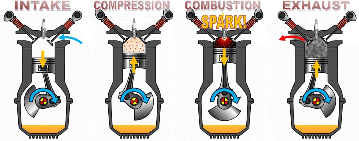 (FYI an animated gif of a 4-stroke engine can be seen at: energyeducation.ca/Four_stroke_engine) This section will be FOCUSING ON TIMING within the COMBUSTION CYCLE Picking the right place to create the IGNITION SPARK in the combustion cycle is about matching that spark to the PEAK in-cylinder combustion pressure. For best results, the MOST SPARK needs to be timed to a point in the cycle where it has the MOST LEVERAGE on the crankshaft during the POWER STROKE. And we know the Power Stroke begins just after TDC (Top Dead Center). 
What is PEAK in-cylinder combustion pressure? In-cylinder pressure is the pressure in your cylinder during the combustion stroke. The pressure is caused by the ignition of fuel mixed with air. The fuel in the combustion chamber doesn't really explode. It's not instantaneous. It BURNS and that burn can be measured in milliseconds, so it takes an amount of time. The PEAK pressure happens when the fuel combustion has made the biggest "flash" possible during that burn process. If you were able to video the fuel combustion and then watch it in slow-motion, you might see when that brightest "flash" occurs. That will be your PEAK in-cylinder combustion pressure. This PEAK offers the BEST benefit as long as it's timed to happen at the most opportune point in the combustion stroke. A Discussion of leverage. Introduction to MBT Timing. Experience tells us the best crank LEVERAGE occurs around 12° to 15° ATDC (After Top Dead Center). If we understand that, then we need to move ignition spark timing ahead to compensate for the fuel burn rate, which will affect how long it takes for that PEAK FLASH to happen. To compensate for that correctly, we need to time it considering the engine speed, cylinder filling time, temperatures, various air/fuel mixtures, and more. Whatever timing value we come up with to get this "perfect" formula is called MBT Timing (Maximum Brake Torque Timing). MBT Timing results in the best possible torque, or leverage, when pushing the crankshaft DOWN during the power stroke. If we were ignorant of this stuff and we decided to just time the spark to begin at 12° to 15° ATDC it would be way too late, because the fuel needs time to burn. So we MUST ignite the fuel ahead of time. So when you see that an engine at idle is set to spark at 12° BTDC (Before Top Dead Center), you can get the picture that the fuel needs significant time to burn before it reaches the best combustion pressure at 12° to 15° ATDC (After Top Dead Center). If you're trying to determine precisely where MBT Timing is for your engine, that can be done on a dyno, even at lower RPMS if necessary. There's a dyno testing video coming up below, which will show a technique used to find MBT Timing. The distance from 12º BTDC to 12º ATDC is 24º of engine rotation; If you're a good math nerd, you can figure out how much time it takes for the engine to rotate 24º at 900 RPM (which equals 15 revolutions per second). Here's the ANSWER: It's 0.004 seconds (4 milliseconds). If you search hard you'll find info suggesting that a gasoline/air mixture can take around 0.002 seconds (2 milliseconds) to light. So the key to all this is timing the PEAK ENERGY of that burn to push the piston down at the right time. This burn might occur a bit faster or slower depending on air/fuel ratio and engine compression ratio (which is affected also by boost level), etc. Then as the engine RPM speeds up, it will need a bit MORE spark advance to KEEP the fuel burning in time. So an ignition system with spark advance will take advantage of this and add a little more spark advance when the engine speeds up faster than idle. This image below will offer some technical comparisons of fuel burn speed. Different fuels are shown, as well as different CRs (compression ratios). Higher CRs burn faster than lower CRs. This also means a turbo boosted fuel mixture burns faster. This is an easy thing to understand, since we already know that compressing the fuel mixture makes the mixture more DENSE, which then releases more power when it burns. The higher the compression the better. This helps explain why a 20:1 CR diesel engine can create huge torque numbers.  The OTHER thing we can discover from this image above is the fuel burn speed compared to the air/fuel mixture. A Lambda measurement of 1.0, or "STOICH" refers to the air/fuel mixture which is considered to be optimum. For gasoline, STOICH would be an air/fuel mixture of about 14.7 to 1. This image shows us that the fastest combustion occurs near STOICH or maybe slighter richer than STOICH for some fuels. If you go too lean or too rich, the combustion speed slows down and these graphs support that drop off, BUT the speed drop-off is not really very dramatic. It's a very small drop. So if you're now wondering what the point of this part is relative to IGNITION TIMING, here it is: There are some theories out there (and some videos and articles exist) which suggest the speed of fuel combustion should be compensated by the amount of ignition advance: i.e; it can suggests a LEANER mixture should get MORE timing advance and a RICHER mixture should get LESS timing advance. Maybe there's a small point to that reasoning on a deep level, but it's my opinion the burn speed differences are way too small to allow this micro-crap to take up very much valuable time and brain energy. At least for us DIYers. Feel free to email me if you want to comment.
I want to discuss ignition timing in your engine for the broad range of engine RPM, which you might choose to set (if you COULD change settings) for more power, better economy, etc. The below video offers a good look at the basics of how tuning the ignition timing can be done for the benefit of more power. And THIS video shows how MBT timing is discovered. VIDEO: Dyno testing ignition timing for maximum power through the engine RPM range. Naturally aspirated (non-boosted). https://www.youtube.com/watch?v=AX2bn_4GEDI When you're deciding what to do with spark timing as the RPM increases, videos like this can help. There are a few fundamentals you should know. 1. The timing map should generally be created from idle to redline (with redline being your maximum usable RPM). 2. Testing like in the above video should first be done at FULL-THROTTLE with no vacuum advance devices, and (if a turbo) no boost retard devices. Also if it's a turbo, no boost should be allowed in this testing. NONE. In the above video, this engine is tested through the RPM range a number of times at full throttle. In the first tests, the spark is set at a low static timing setting. This can begin at i.e. 15º BTDC (Before Top Dead Center). So then this 15º setting is used through the first full rev-test all the way to redline. Again, no advance is allowed. This way the engine performance can be measured at all RPMs at only THAT 15º static spark setting. Then another test is done at a higher spark setting (i.e. 20º BTDC). Then another at i.e. 25º BTDC, etc. Watch how that's done in the video. This will eventually give you a good idea how the engine runs at full power at various RPMs with each separate spark setting. The peak power info for each test run can used to begin creating a basic spark advance map which will ensure you have MBT timing at all RPMs. 3. The total timing upper ADVANCE limit in most cases for a naturally aspirated engine should be approximately between 25 and 35 degrees, including the base ignition timing at idle. This is the maximum spark timing that you will allow at any RPM. This means that if we assume your base idle timing is 12 degrees BTDC, then you have another 13 to 23 degrees to figure out after idle. Since I'm sticking to mostly BASIC info for now, I won't go into any detail about a boosted engine yet, except to say that most boosted engines will always have a way to reduce total timing when under boost (boost ignition retard). More info later on boosted engines. 4. Most of the TIMING INCREASE in your ignition map will happen between IDLE and CRUISING RPM; cruising is normally about 2500 to 3000 RPM. I'll use 2500 RPM for a cruising example for this discussion below. So if we look at the B21FT example, the timing from idle to 2500 RPM is from 12º to about 27º. Then if there's any timing left in your maximum (which was discovered during the above MBT timing full-throttle tests), that extra can be added between that 2500 RPM cruise and redline. TRIVIA NOTE: PARALLEL VALVES vs ANGLED VALVES There is a theory in the small aviation engine world about "accepted" base ignition timing numbers that I want to share. The reason I have such obscure info in my head is because I use SDS EFI in my 240 (www.sdsefi.com). Besides being used in racing engines, SDS EFI is also used in aircraft engines. In the aviation world the accepted MAXIMUM total timing advance for a PARALLEL VALVE engine (Lycoming for example) is 25 degrees. The MAXIMUM for an ANGLED VALVE engine is 20-22 degrees. I can't vouch for the relevance of this to a Volvo engine. It might just be random info to help keep your mind more cluttered, but keep in mind a Volvo B21, B23, or B230 8-valve is a parallel valve engine. A Volvo B234 (16 valve DOHC) is an angled valve engine.  Here's a simple example base map below showing how this might look using the numbers in steps #3 and #4 above. This gives you a BASE or a beginning point to start, before you introduce other things that will add to the confusion and make more changes to your timing. If you're in a position where you don't yet know what base numbers to use, the best numbers will mimic what the stock factory ignition system used. I suggest that you use that until you know what changes to make.
PRE-MADE BASE MAPS If you're using an aftermarket engine management system, you should know that some systems will have pre-made base maps for lots of different engines, which you can use as a beginning point. Haltech and MaxxECU are some that offer base maps in their programs for almost any engine ever made. WARNING TO NOT PURSUE MORE TIMING UNLESS YOU KNOW. You may be tempted to add more total timing, because you've read or heard somewhere that more timing is more power. This is only true until more timing reduces power. You'll probably see spark maps made by other people who tell you 30 or 35 degrees or MORE of total timing works for their engine. Before you copy those maps, let's have another discussion about this image below so you can have a better understanding of why adding more base timing might not always be a good idea. The above image shows spark occurring at TDC (Top Dead Center). If you've been reading, you know that the spark actually needs to begin the fuel burn before TDC for the fuel to burn in time. Now look at the image above with "12º- 15º ATDC". It shows burning fuel is starting to push the piston down. We've already seen that the best location for the best leverage for that burn energy to PEAK is at about 12º-15º ATDC. That's a pretty specific place, isn't it? This should give you a clue that precision is king here. So if you add MORE TIMING because it sounds like a cool idea and the fuel burn begins too soon, then some of that energy gets used up before the piston can get into the best PEAK position to be pushed down. In simple terms, that results in less power available to push it down. It's easy for this to happen without you noticing if you've chosen more timing than the engine needs. The ultimate test of course is dyno testing. So this is why I recommend staying with FACTORY NUMBERS for the base map until you test it yourself or until you find a really good reason to change. Take a few minutes to watch this video below. This guy is dyno testing a 400 HP V8 that's mostly stock. The factory ignition has set the maxxed out timing advance at only 18º BTDC. Yeah, that's not much, but this is a good example to study. He decides to dyno test the peak power at 18º, 20º, 22º, 24º and 26º BTDC. I'm not surprised that he finds the most power with a max advance of 26º. And I suspect he was aware that number was going to be the best he was going to get if he had kept going. If he had used someone else's idea of a "good" map (advancing to something like 36 degrees), he might have risked getting less power. https://www.youtube.com/watch?v=kRdHfMgkCwk Beyond the Basics. Using Vacuum Advance to further alter Timing (for part-throttle cruising only). The next step for your ignition is to find out if slightly different spark timing could improve things at certain RPMs under PART-THROTTLE CRUISE (when your engine typically sees the most manifold vacuum ever). Remember, the above spark advance map and discussion was all about finding the best FULL-THROTTLE spark settings. Now we can look at part-throttle. The best example of part-throttle in my mind is cruising on the highway is at around 2500 rpm. Don't mix this up. This is not the same as the 2500 RPM timing we discussed before (which was for POWER). Now we're discussing cruise efficiency only. Some engines will become more efficient if the timing is advanced a bit during part-throttle cruise. This was the reason why many cars (including old Volvos) had vacuum diaphragms on the distributors. These efficiency improvements in the engine might be harder to measure. It's still possible using a dynamometer, but most people just do these tests on a highway or maybe they try comparing MPG results. If you goof in this area then you probably won't hurt the engine. You might only get slightly less gas mileage or slight better torque when climbing grades. Some engines respond to these changes and some don't. For example, if your using the 2500 RPM setting of 28º from the below table, you might find that during part-throttle cruise the engine would do better with a little extra spark advance at that cruise speed. An ignition system that can read changing manifold vacuum levels and use info that to make timing adjustments during steady part-throttle cruise for better economy is a good thing if it results in the engine performing better.
 The above vacuum-boost gauges are pretty common. The first one here uses inHG to measure engine vacuum. The other uses inHG to measure vacuum and PSI to measure boost. kPa (Kilopascal) for Vacuum/Boost Measurement You'll find that there are lots of spark advance tuning maps out there that use OTHER parameters for vacuum or boost. kPa (Kilopascal) is a very common one for editing ignition maps (but it's not usually used for a vacuum gauge). And kPa can be commonly used to measure BOTH vacuum AND boost. If you need to convert from one parameter to another, there are easy-to-find conversion calculators on-line. With most engine tuning tables that use kPa for both vacuum and boost, 100 kPa will usually represent AMBIENT atmospheric pressure at sea level. So anything under 100 kPa would be vacuum. Anything over 100 kPa would be pressure (or boost).  An automotive gauge measuring vacuum in kPa is not as common, but if you had one like this ABOVE, it would read near ZERO with your engine off. Your engine might reach up to around 850 kPa vacuum (8.5 x100 on this gauge) under closed-throttle deceleration (engine braking). The maximum vacuum possible will be about 1000 kPa (10 x100 on this gauge), although your engine vacuum will never actually get that high. As mentioned, most engine tuning tables that use kPa for vacuum and boost will measure it differently than the above gauge. On many tables 100 kPa (instead of zero) will often represent normal AMBIENT pressure at sea level. This would be the reading you see with your engine off. Here's an example:
In the above example, noted that I added 7 degrees at cruise. It's not uncommon for some cars to add 15 degrees or more just for this kind of freeway economy arrangement. Using Vacuum AND Boost to Alter Timing. An example: A Volvo B21FT (1981-85) will typically have an ignition timing advance map like this one below. 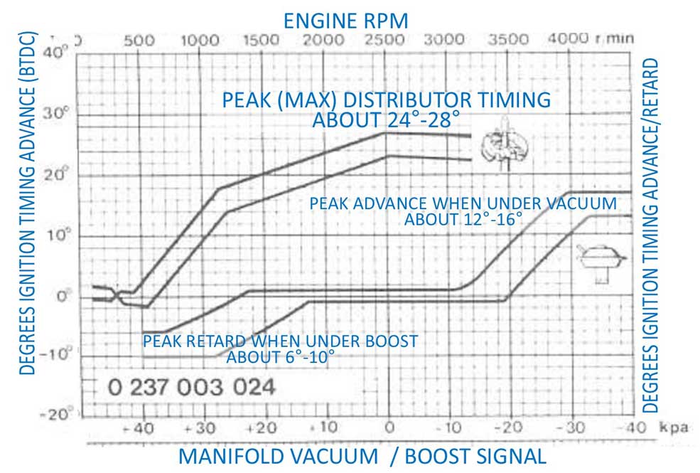 Volvo Ignition System Manual TP30432 pg 16. This is the same distributor timing map I showed you before for the B21FT, except I have now added information for the dual vacuum/boost diaphragm found on this distributor. This dual diaphragm was considered to be pretty advanced in 1981 and it worked pretty well for a B21FT at the time. It looks similar to diaphragms on non-turbo engines of the era, but those were designed to control timing advance only during part throttle cruise. A detailed explanation of this DUAL diaphragm canister is below. Using this Diaphragm when under VACUUM. This diaphragm advances ignition timing when vacuum is present, except at idle (more details on this will be in the Ported Vacuum section below). This advance function is primarily for fuel economy. The diaphragm can advance timing up to about 12 to 16 degrees over the normal timing map during part-throttle cruise. An increase like this offers more part-throttle engine torque at a point when it's safe, because the engine is not under a great load during part-throttle cruise. This helps to increase fuel economy. Using this Diaphragm when under BOOST. This part of the diaphragm retards ignition timing when BOOST is present. This is primarily for engine safety reasons. An engine under boost and load develops more torque and a lot more cylinder pressure. More torque is awesome, but the higher cylinder pressure comes with a lot more stress and heat, which can damage the engine if it's excessive. So this is designed to protect the engine by retarding the timing curve as boost increases. The amount of boost retard with this diaphragm was set to max out at about 6 to 10 degrees when full boost was at about 6 PSI for early 240s. Volvo info suggests this changed to about 3 to 7 degrees at full boost for later B21FT versions with the intercooler boost system (late 1984). Full boost for an early B21FT was conservative at only 6 PSI (42 kPa), or at 7.1 to 8.2 PSI (49 to 56 kPa) for later versions with the intercooler. Maximum power for the early B21FT was about 131 HP and 155 ft lbs torque. A later version would make about 162 HP and 181 ft lbs. torque when equipped with the intercooler boost system (late 1984). As a bit of 240 Turbo trivia: The European version B21ET offered more turbo boost than a U.S.A. car. The B21ET developed about 9.2 to 10.1 PSI (64 to 70 kPa), which gave the B21ET more power: about 145 HP and 167 ft lbs.torque. The later B21ET cars were never officially fitted with intercoolers from the factory, but later B19ET cars were (for the Italian market only). The B19ET was almost the same as a B21ET, except with a smaller bore. The later intercooled B19ET cars had 11 to 12.1 PSI (76 to 82 kPa) and developed about 170 HP and 184 ft lbs. torque. If the above factory B21FT distributor timing map was laid out like a more modern timing map, it might look like this map below. Note that the above map uses zero kPa for ambient atmospheric pressure. So this sample scale below will do the same and I will introduce + (plus) or - (minus) pressure settings. In this example, nothing is added for base timing at idle. Idle will be 0º. You would not use this map to set your timing in a B21FT. Remember that I'm showing this to demonstrate ONLY timing advance or retard that the distributor is providing using it's advance or retard mechanism. If you're questioning why some numbers on the vacuum side seem to be off by 10º, this is because the centrifugal (mechanical) advance in a B21FT distributor adds up to 10º of timing at 900 RPM. We've discussed that info before.
Here's another example below. In this example, I have INCLUDED BASE IDLE timing, which is 12º BTDC at 900 RPM. Since the centrifugal (mechanical) advance in a B21FT distributor adds 10 degree automatically at 900 RPM,setting this idle timing to 12º means the distributor gets adjusted +2º. So the purpose of this map table below is to show you the actual, real world timing that a B21FT sees with all devices in normal working order.
PORTED VACUUM versus MANIFOLD VACUUM In a paragraph above I mentioned that the B21FT distributor diaphragm modifies ignition timing when vacuum is detected, except at idle. In this section I want to discuss further what happens at idle and just above idle in an engine when using PORTED VACUUM for the distributor vacuum diaphragm. Engines like the the B21FT have a throttle body with special ports on the side. The vacuum line to the distributor diaphragm does not come from a main manifold vacuum source. It comes from a special port on the throttle body. You can see BELOW this throttle body has two very small vacuum ports on the side facing the cam cover. I've labeled them PORT 1 and PORT 2 in the below images. You can see the opening in PORT 1 is slightly smaller than PORT 2. Both ports are in a position near the edge of the throttle valve; the edge which opens toward the incoming air flow. Due to the positions of these ports, they will not see any vacuum at idle. They see only ambient atmospheric air pressure at idle. When the throttle valve begins to open just a little, the ports will then be slightly below the throttle valve and that's when they'll see manifold VACUUM. This effect is call PORTED VACUUM. So when one of these PORTS is connected to the distributor vacuum diaphragm, this ported vacuum will advance timing under part throttle (which happens during initial part throttle push or during part throttle cruise). 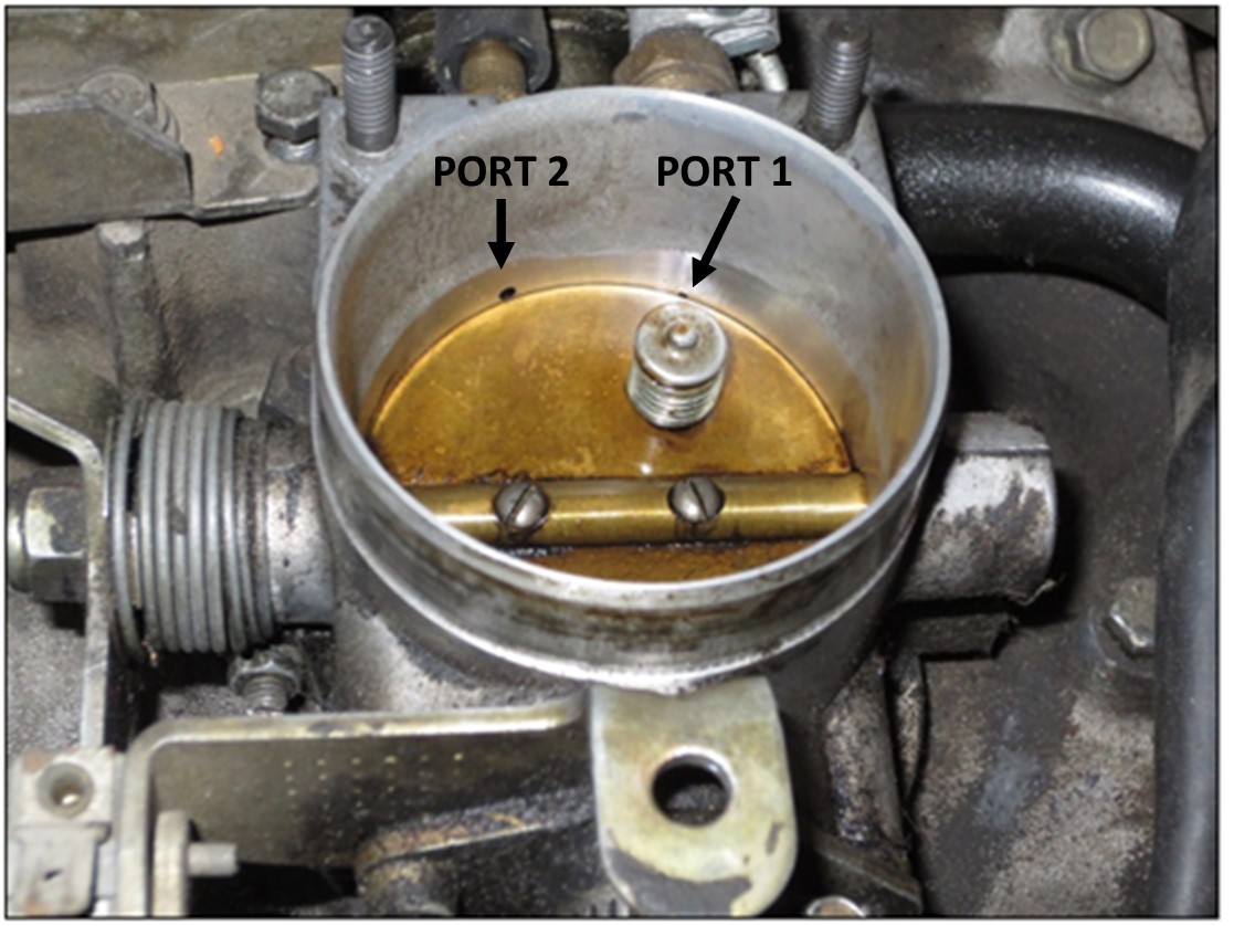 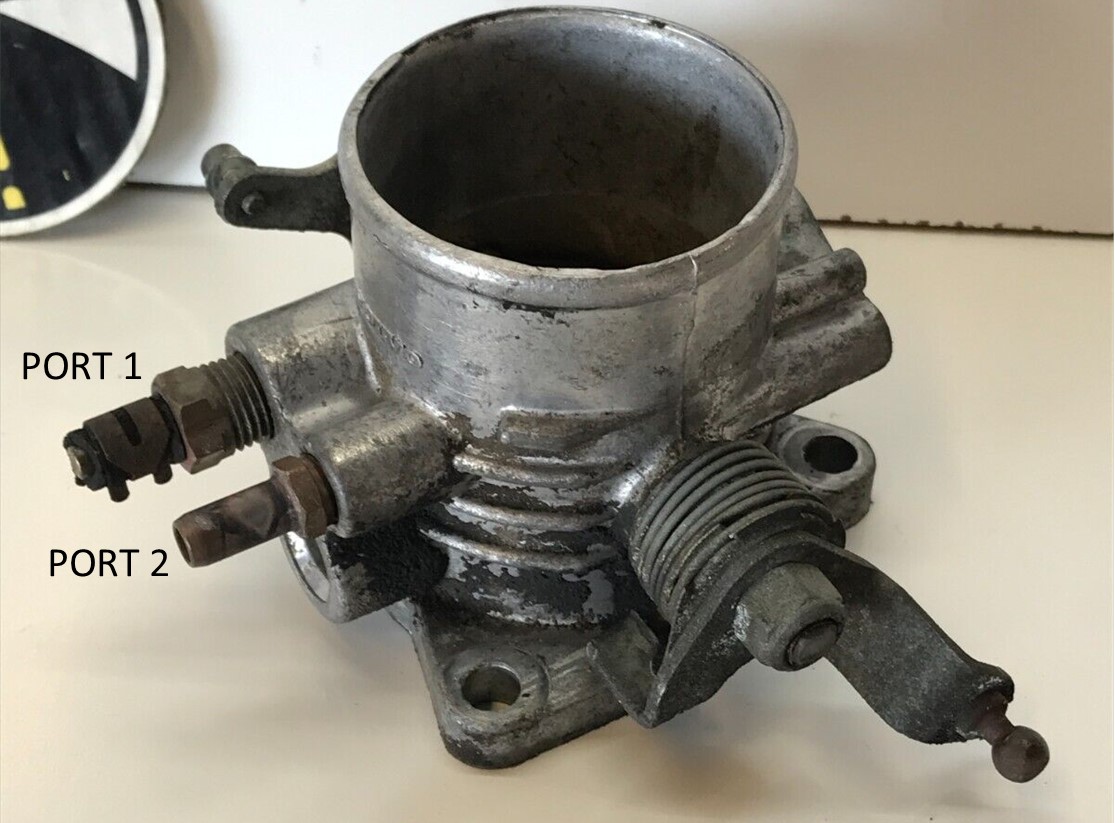 PORTED VACUUM CONTINUED 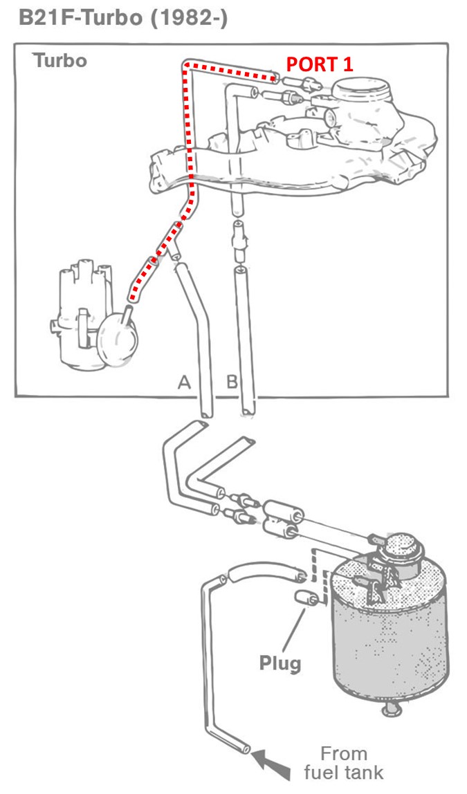 <<< The
vacuum diagram at left is from Volvo greenbook TP30727 discussing 240 emissions. It shows PORT 1 (or line A in the image) which is going to the distributor
diaphragm. This information will show how this vacuum line affects ignition timing in a B21FT. <<< The
vacuum diagram at left is from Volvo greenbook TP30727 discussing 240 emissions. It shows PORT 1 (or line A in the image) which is going to the distributor
diaphragm. This information will show how this vacuum line affects ignition timing in a B21FT. The initial timing at idle is normally set to 12º BTDC by setting or rotating the distributor. The B21FT ignition table we saw above shows us that additional timing advance will occur when this diaphragm sees vacuum, but with this configuration shown in the vacuum diagram, this PORT 1 vacuum circuit gets NO VACUUM at idle. Only when the throttle is slightly opened beyond idle will be when the diaphragm sees vacuum and at THAT time it will begin advancing timing. This increase in ignition timing will help produce more engine torque at part throttle. Besides a potential improvement in fuel economy during part throttle cruise, this can be especially helpful for the B21FT, because the low static compression ratio (7.5 to 1) is generally not very optimal for low RPM acceleration. LABEL ERROR: If you have a 240 Turbo, there's something you might need to know about the BELOW B21FT under hood vacuum hose label. 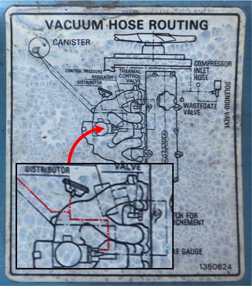 All 240 Turbo vacuum labels like this one show the same thing. If you look closely, you'll notice the throttle body ports are reversed compared to the greenbook diagram above left. The above label shows Port 2 going to the distributor diaphragm. Since I believe the Volvo GREENBOOK diagram is correct (and that actual vacuum plumbing has been confirmed by several 240 Turbo owners), then this suggests all of the vacuum hose routing labels like this one, which Volvo placed under the hood for 240 Turbos, are INCORRECT. To help reinforce this PORTED VACUUM concept into our feeble brains, here are a couple good videos below from someone showing us the difference between ported and manifold vacuum. This video shows an old Ford carbureted engine, but the ported vacuum concept is 100% the same with our old Volvos. https://www.youtube.com/watch?v=ohw1oRlcC4c https://www.youtube.com/watch?v=sLwXlsHBd4k ONE LAST THING ABOUT PORTED versus MANIFOLD VACUUM If you search around much on this topic, you'll undoubtedly come across some videos or articles which will argue about whether or not you SHOULD USE ported vacuum for a vacuum advance distributor diaphragm. You'll find people who will defend using normal MANIFOLD vacuum instead for that purpose or they'll insist THEIR testing proves THEIR engine runs BEST using normal manifold vacuum. When you see that, feel free to analyze it and work out precisely what the timing advance looks like and WHEN that vacuum appears compared to WHEN it appears with a ported vacuum source. Try to see whether it seems real or not. Some people will insist that ported vacuum was only for emissions and it's not relevant for economy or performance. I'll argue that maybe it WAS for emissions PARTLY, but I believe it can also be about economy. Sometimes there's a fine line between running better or worse with too much timing at the wrong RPM. Hopefully you can make your own informed decision on this and not just take the word of others without a good look at it. More modern ignition system timing maps using both VACUUM AND BOOST. These maps below use kPa for vacuum and boost reference. Unlike the factory B21FT map image that uses 0 kPa for ambient pressure, Microsquirt and many other systems use 100 kPa to designate ambient atmospheric pressure. So then for these maps any number below 100 kPa is vacuum and any number above 100 kPa is boost. 200 kPa equals 1 bar of boost (about 15 PSI). Here's a CAUTIONARY example below of a spark map you might find that was made in Microsquirt. Someone made and shared this map online for a Volvo 4 cylinder (with turbo). This is not a typical B21FT or B230FT map. This one was custom made for an unknown custom Volvo turbo with unknown static compression and it uses a lot more total timing than a typical Volvo map. I have no idea if these numbers can actually work ok on a typical Volvo. The engine would run, but the big question is would it run well or safely? This map was shared in TB as an "example" to help others set their basic timing. The problem is no info was offered about it's use. Pump gas or Ethanol? Engine compression? Nope. Was it verified with dyno testing? Nope. Please don't assume that the factory timing numbers no longer apply to your engine, just because you changed a cam, added a turbo or increased boost. Volvo engineers probably put in lots of work to come up with those numbers. Copying a map like this above for your use should not be done, unless you know the engine info and fuel used and you can trust the tests that helped create it. 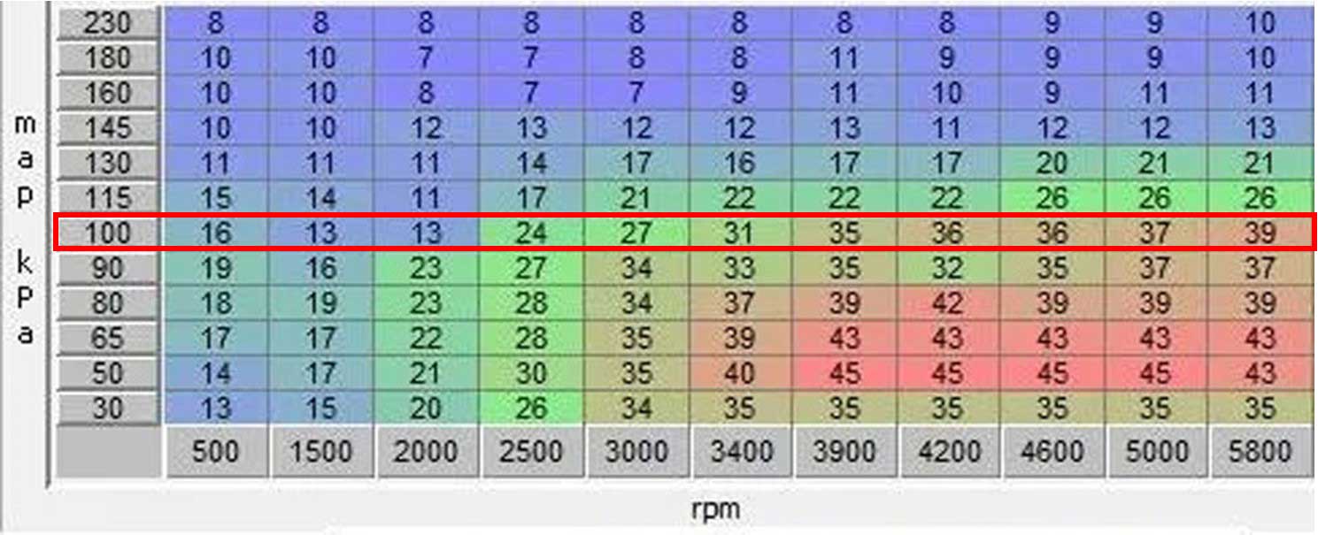 Here's another modern timing map BELOW which shows much more conservative max timing numbers (27 degrees max in the base map in the red bordered box). These numbers came from a known and trusted friend and they're backed up by real dyno tests for a Volvo B230 Turbo 8-valve producing over 500 hp at the wheels. This map below was using pump gas, however higher power was made using ethanol. The ethanol map was very similar to this, but it added about 2 degrees extra timing under boost. 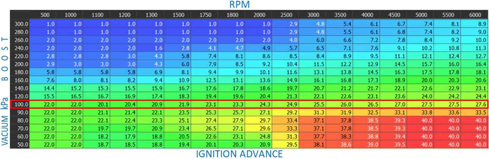 If you're newer to this stuff and the large number of boxes in images like this seem like too much to grasp, try concentrating first on just the base map in the middle inside the red border that I added above. That base map will be the basic spark timing advance for this engine before any changes are made by vacuum or boost. That's a good place to begin. Once you have an understanding of a base map, then you can begin to better understand how small changes below 100 kPa (in VACUUM) make changes, and also how small changes above 100 kPa (in BOOST) make changes. If you've had experience with Megasquirt, Microsquirt, Haltech, Motec, MaxxECU or other aftermarket systems, then you're familiar with using kPa for vacuum and boost values. When I first moved from Bosch K-Jet to programmable EFI in the 1990s, my first experiences began with SDS EFI (Simple Digital Systems), which I still use on my 1984 242 Turbo. More info on that HERE. SDS EFI was primarily designed as a race car engine management system. It doesn't use kPa at all. It uses old school PSI and inHG values for boost and vacuum, but the programming is otherwise pretty much like the more modern systems. Speaking of MaxxECU, if it interests you, there's a discussion thread about it in TB: turbobricks.com/maxxecu-questions-and-support.366580/ A Little Extra: Using ignition timing to help achieve a better, more stable idle speed. This section will discuss IDLE ONLY. Getting a decent idle may seem a bit over-simplified. You just make sure the air/fuel is decent and your idle timing is set for something like 12º BTDC and move on, right? Not necessarily. If you find that your ignition system offers more capabilities which might help improve a more stable idle, then try using them. I'm not talking about using PWM idle valves or controlling an electronic throttle body. I don't have any of those. I'm just talking about using ignition timing to optimize your idle. Let's assume you have a 4 cylinder that has an idle target of 900 RPM and base idle timing is 12º BTDC. If your system will allow you to control ignition timing at idle independently from timing for other uses, then a good way to help maintain a stable idle is to make it so that it increases timing advance if the idle dips below your 900 RPM target. And it reduces timing advance if your idle rises above your target. Some systems will allow you to program such a timing change. Some systems will allow stepped changes if the idle deviates more than 50 RPM under or over your target idle. Some systems may not have that much resolution and it may only allow changes if it deviates more than 100 or 250 RPM. A timing change for a deviation of over 50 RPM could feasibly be 5 to 8 degrees. For a 250 RPM deviation it could be 10 to 15 degrees. With this type of system in place, when idle speed dips, ignition timing is increased, which will increase the RPM. When idle speed rises too high, ignition timing is retarded, which will decrease the RPM. This can have a nice stabilizing effect. Doing something like this will not usually take the place of your main idle speed controls, such as an air bypass or idle valve. It's only intended as an enhancement, however it's not uncommon for a race car to use something like this without an idle valve or any other device, since a perfect idle is not usually a priority for a race car. There are some limits to observe. I consider a typical normal idle timing to be around 12º to 18º BTDC, but if you plan to set your idle timing higher, like at over 20º, then you may find that advancing the timing with this scheme may not increase RPM as easily. The reason is that you as timing increases, it may be getting very close to MBT Timing (I discussed MBT earlier HERE). Pushing idle timing advance beyond MBT will not produce more torque or more RPM. If this happens, you could still use the retard side of this scheme. Here's a good article that will give you some more useful things. autospeed.com/cms/a_109132/article That's pretty much it. I welcome your comments or questions. If you can add to any info here, please email me. CONTACT ME. |
|||||||||||||||||||||||||||||||||||||||||||||||||||||||||||||||||||||||||||||||||||||||||||||||||||||||||||||||||||||||||||||||||||||||||||||||||||||||||||||||||||||||||||||||||||||||||||||||||||||||||||||||||||||||||||||||||||||||||||||||||||||||||||||||||||||||||||||||||||||||||||||||||||||||||||||||||||||||||||||||||||||||||||||||||||||||||||||||||||||||||||||||||||||||||||||||||||||||||||||||||||||||||||||||||||||||||||||||||||||||||||||||||||||||||||||||||||||||
| Non-Factory or Aftermarket Ignition Options for Volvos |
|
| MSD Ignition Amplifier A tool for curing Spark Plug Blowout in a Turbo Car |
|
If you own a 240 Turbo
and it has the factory ignition system, you might discover that the factory
ignition spark is rather weak. It's usually ok if there are no
performance modifications, but if you increase boost,
you'll likely
discover soon that the spark is not strong enough and the engine might
experience sudden misses while under load with elevated boost. It's called spark
blow-out and it'll appear as a very strong miss or sudden engine cut-out when under boost. It happens
to weak ignition sparks when an elevated level of boost is added. A higher compression or more boost in the combustion chamber
makes it more difficult for a spark plug to ignite the fuel mixture, so a weak spark won't do in this circumstance. If this
happens to you, one quick cure is to REDUCE the SPARK PLUG GAP to
about HALF of NORMAL. This is not the best way to fix this.
Don't bother installing a high-performance coil or better spark plug wires or better spark plugs. Those will never cure this. INSTALLING AN MSD IGNITION AMPLIFIER HAS ALWAYS WORKED FOR ME. The MSD Digital 6A ignition amplifier (PN 6201) and the MSD Tach Adapter (PN 8910) are needed. These two devices are added to the existing Volvo ignition system to amplify your spark. No wires from your existing ignition are removed. You can read more about what the MSD box does at their site, but in short, it seriously amplifies the spark for your factory ignition and in my experience it will fix spark blow-out.
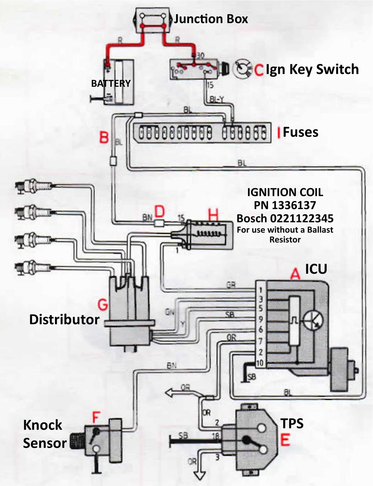
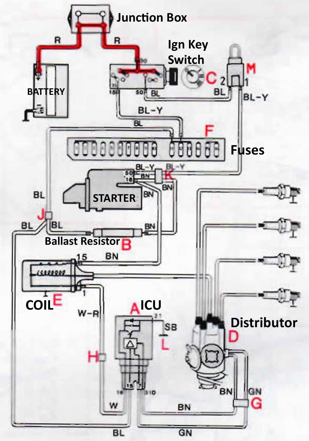
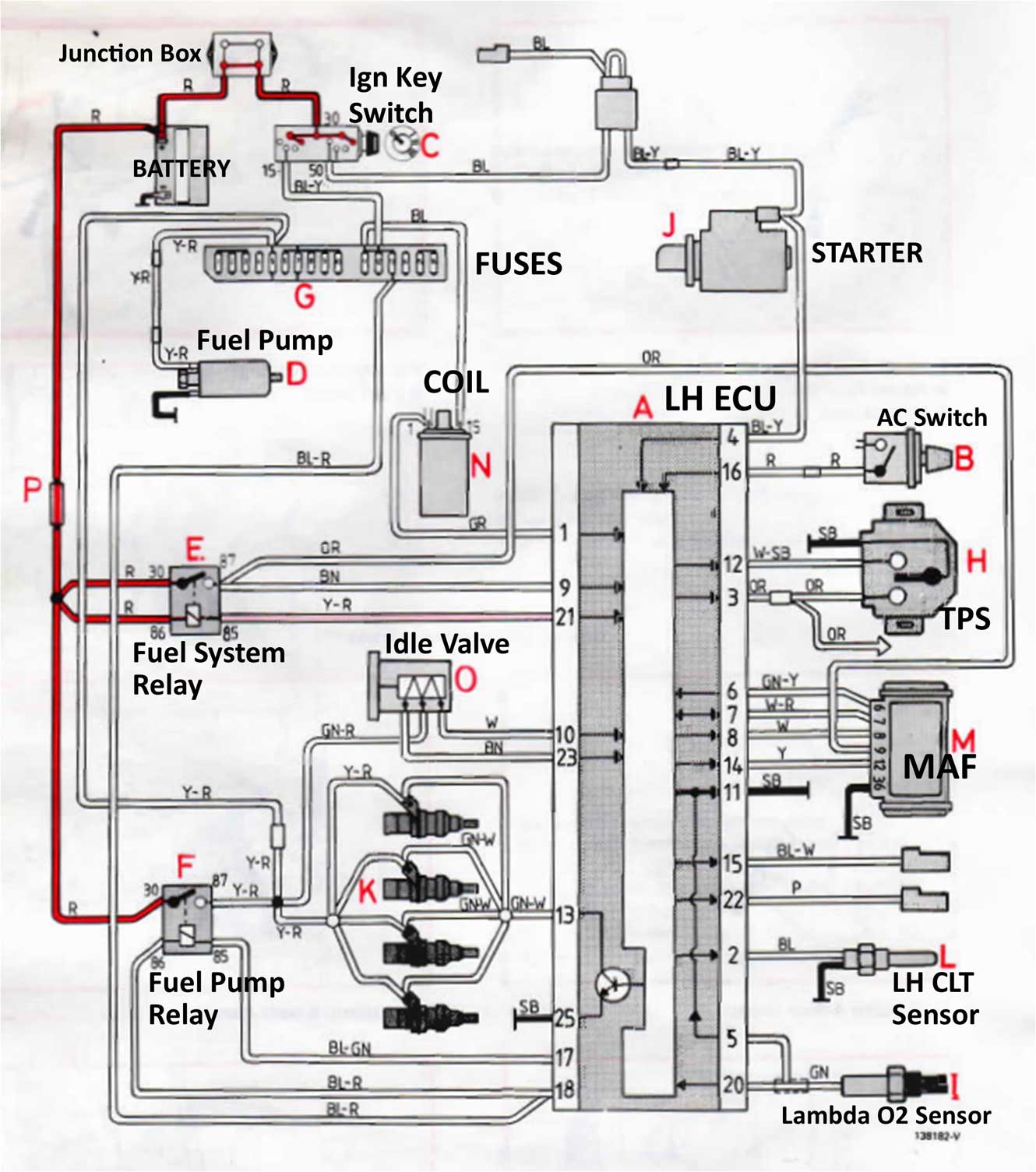
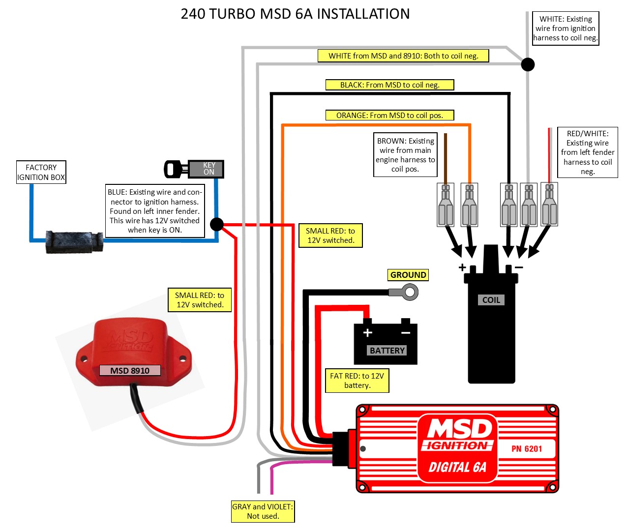 If you need any of these tabs for your coil, you can search for 6 mm Faston Tabs. They're easily available as single or double tabs like these below. 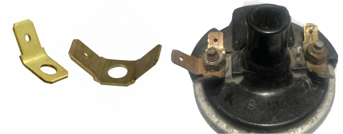 Here's a diagram showing the same installation if you have a 1985-88 240 with LH 2.2 and standard ignition (and perhaps you have added a turbo). 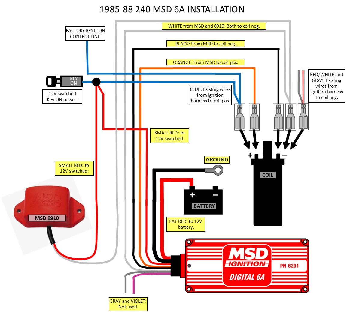 |
| Spark Plug Cables |
| How to Build a DIY Custom Cable Set for your 240. | ||||||||||||||||||||||||
| A number of years ago I
decided I wanted a nice looking and long lasting spark plug cable set. I
wanted something extra special, tougher and nicer looking than the ordinary sets than I
could buy from the normal places. So i decided to buy a good crimp tool
and the parts needed to make it happen.
So how long do these cables last? Good question. I built these shown below in 2010 and they were still going strong at this writing in 2021. I don't build these for sale. I have created a guide below for YOU to build your own.

TOOLS This MSD 35051 crimp tool is pretty expensive, close to $100. I bought mine from Summit Racing: summitracing.com//msd-35051  Years ago the selection of inexpensive crimp tools was not nearly as good as it is now. Now you can probably get away with a much cheaper version, such as this one from Amazon for $27: amazon.com/Crimping/B08JG3K2HF/  Also MSD now has an inexpensive Mini-Crimper for about $10, which is used with a vise. I haven't used it, but one of the videos I found near the bottom of this page shows it in use. 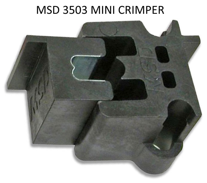
If you use all of the options shown below (which I did), expect to spend over $200. Yes, that's lot. But keep in mind that some items can only be bought in certain lengths or minimum packages, so you will have leftover parts. You COULD save some money by building TWO or more sets and then sell the others to friends. But if you're a beginner, I recommend starting with making one. Then decide if you want to keep going. SOURCES: I bought parts from several sources. Not every source had all the pieces I needed. Most parts can be found at Summit Racing or Speedway Motors. I have bought from both. There are plenty of other sources, but these were the main sources I used. Most of the parts are made by MSD. They charge a premium. If you want to shop around for other brands, there are other ignition cable parts suppliers out there; Taylor: www.taylorvertex.com/, Kingsborne: www.kingsbornewires.com/. If you don't like RED, pick another color when you make yours. 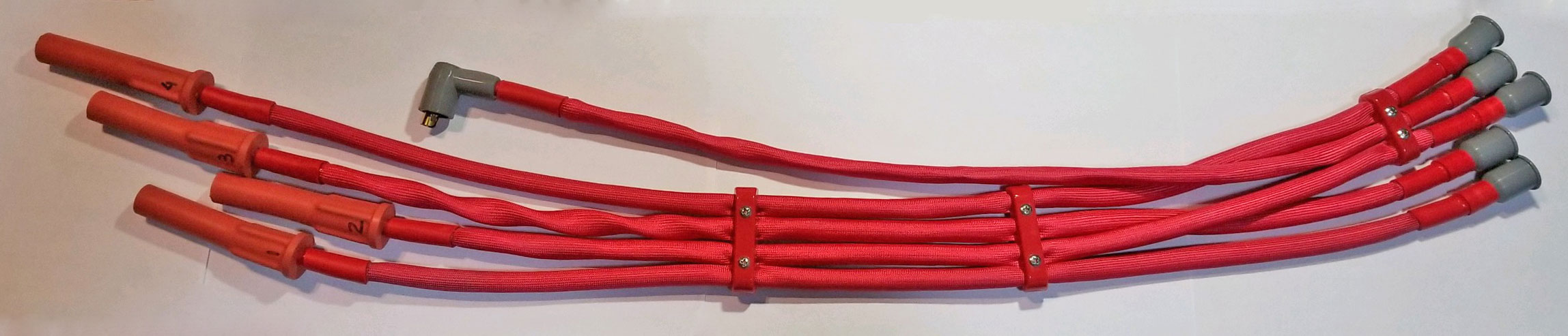 Below image with added thermal boots on the spark plug ends. 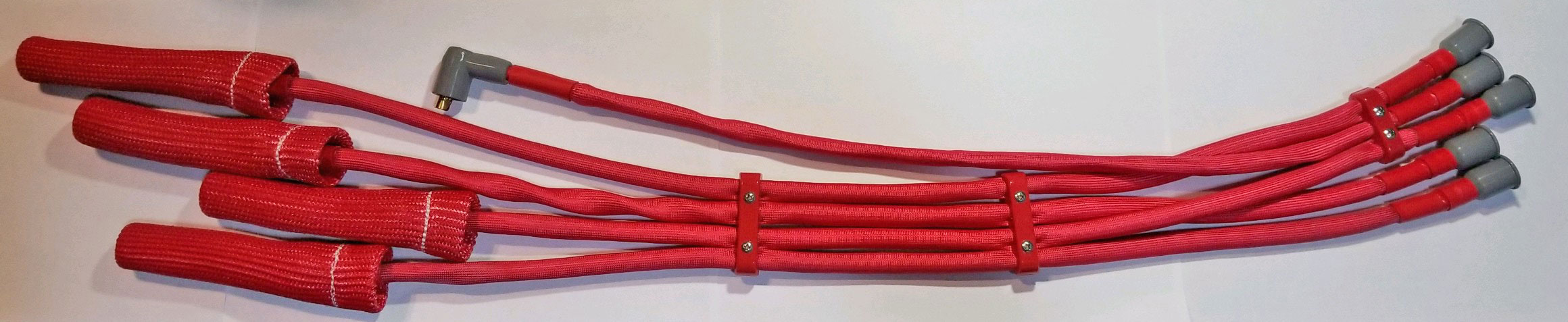 You can begin with a 25 foot roll of MSD 8.5 mm cable. About $68. You can order it in different lengths beginning with 10 feet. The total amount I used for this 4 cylinder project was about 13 feet. summitracing.com/spark-plug-wire-bulk-wire speedwaymotors.com/bulk+wire+8.5  MSD 8854 high-temp spark plug boots with terminals. Cost was about $28 for set of 8 boots. These are ONLY available in sets of 8. MSD offers other boots, but I chose these. summitracing.com/boots speedwaymotors.com/boots 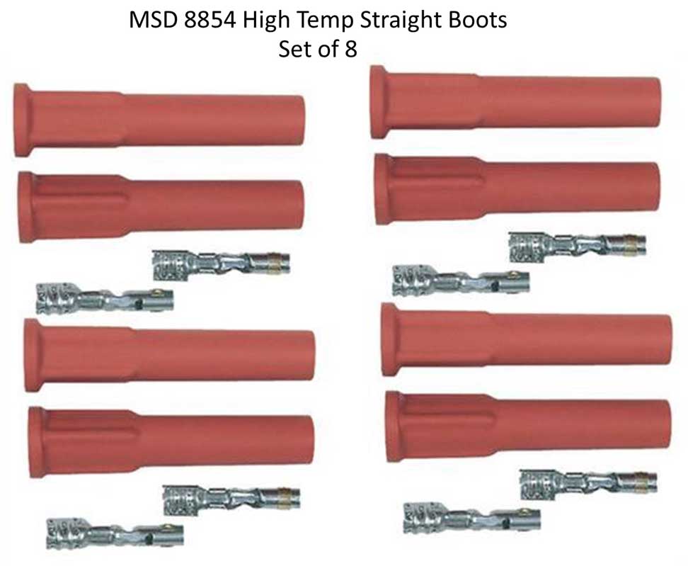 MSD 3321 90 degree DISTRIBUTOR Boot with crimp terminal. TWO sets per package (about $8). I call this a DISTRIBUTOR BOOT, but Summit Racing or other places may refer to it as a COIL BOOT. These boots are easily confused with the below 3331 90 degree COIL BOOT. These are slightly smaller and designed for use on a distributor, although possibly they are interchangeable. So if you prefer a right-angle center distributor boot on your distributor (for the coil wire), then this is one you can use. For my preference, I used a STRAIGHT center boot for the distributor when I made mine (further below). summitracing.com/boots speedwaymotors.com/boots 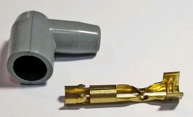
MSD 3331 90 degree COIL boot with crimp terminal. ONE set per package (about $7). This boot looks very much like the above. It's different. This one has a larger hole on the big end. The crimp terminal is the same. summitracing.com/boots speedwaymotors.com/boots 
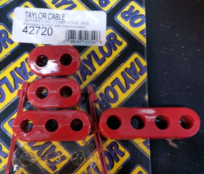
 Here are both of them side by side. The large end opening for the small 3321 boot is 14 mm. The large 3331 boot is 15 mm and this larger boot fits the Bosch coil well. Both are very flexible silicone. 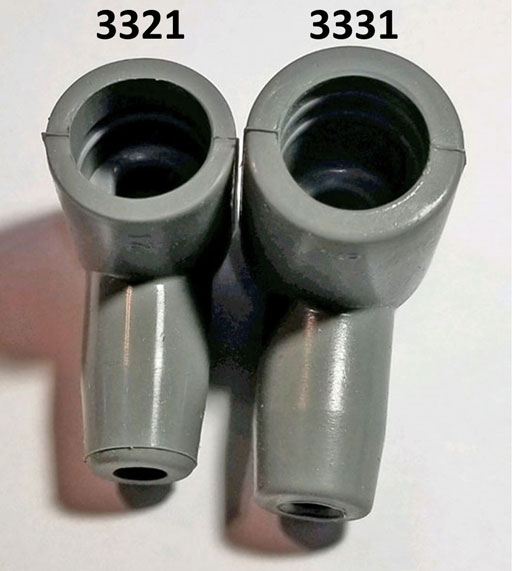 MSD 3322 STRAIGHT Distributor Boots. These only come in a set of TWO with crimp terminals. About $10. You need THREE sets if you need 5 boots. Many OEM Volvo style wires are made using FOUR straight boots and one 90 degree center boot on the distributor. In this case you would TWO sets and you would use the 90 degree DISTRIBUTOR boot above. These boots are made in RED or GRAY, but red can be hard to find. It was for me. Last time I ordered I could only find them in GRAY. Some places might show RED, but you might still get GRAY. summitracing.com/boots speedwaymotors.com/boots  Thermal outer sleeve. I have used both the DEI sleeve below and TechFlex Insultherm Tru-Fit. Insultherm is a much heavier product, because it has real insulation properties. Also it's less flexible. It's more expensive too. The DEI sleeve is only 10 mm wide inside and will fit over 8.5 mm cable, just barely. It will be very, very snug on 8.5 MSD wire and just about impossible to slip on without some lubrication for long pieces, however it will also expand slightly when you push on it. Be sure to use a lubricant (soapy water or maybe Simple Green cleaner). This sleeve would be a much better fit if it was 1/2 inch wide. DEI sleeve will NOT fit over larger 10 mm cable. DEI sleeve is about $30 for 50 feet: summitracing.com/parts/dei-010621b50  Insultherm Tru-Fit comes in a variety of sizes and colors. I have used 1/2 inch size, which is very easy to slip onto 8.5 mm cable. Cost was $38 for 25 feet: wirecare.com//insultherm-tru-fit  Buy some DUAL WALL heat shrink tubing to seal the thermal sleeve ends. I recommend 1 inch diameter, 3:1 shrink ratio. DUAL WALL means there is adhesive inside. That adhesive keeps this stuff in place. Standard heat shrink will move out of place on your wires. Buy a couple feet of this.  Thermo-Tec 14261 spark plug boot protectors. 6 inches long. Set of 4. About $38.00. These are not required, but they will help to make your wires and plug boots last longer. There are a number of competitors making similar boot protectors. summitracing.com/spark-plug-boot-protectors speedwaymotors.com/Protectors  The high radiant heat from the exhaust or turbo will eventually discolor these protectors, but it will take years. These pictured below have been in my car next to the turbo for 11 years. Maybe these are too expensive to just keep buying more, so if YOU'RE CHEAP and this discoloration bothers you, you might just just try re-spraying them with some high heat red aerosol paint to renew them. It should be a BRIGHT RED if possible. Many engine enamel red colors are a darker red. 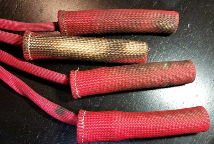 Taylor 42729 Wire Separators, red plastic, (Size: LARGE HOLES). About $16.00. These have large 3/8 inch holes, which will be needed if you're adding the sleeve to your wires. If you accidentally get the smaller separators (like I did once), you can drill them out using a 3/8 inch drill bit. A package comes with two of each piece. If you want more than TWO of the 4-hole pieces, buy two sets. summitracing.com/taylor-cable 
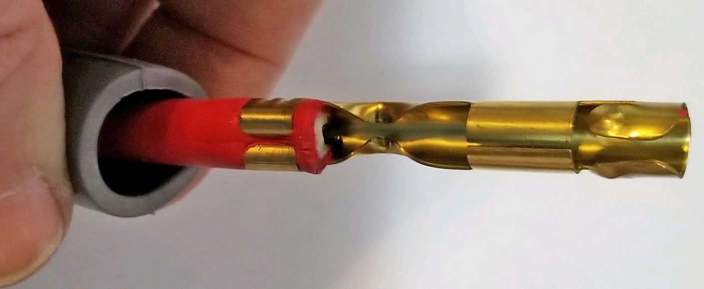
DISTRIBUTOR WIRES Spark Plug End I prefer to begin the assembly with the spark plug end. You'll need to lube the boot to push the wire through. I like using a water based cleaner, such as Simple Green or soapy water. WD-40 will be OK if that's all you have. Some MSD videos suggest that you can push the wire through AFTER the terminal is installed. For these photos below, I did this before installing the terminal. 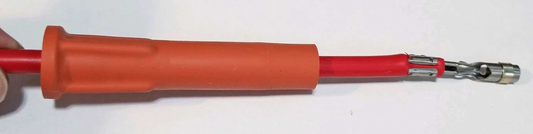 This terminal is known as a "DUAL CRIMP" terminal because two crimps are made. About 1/4 inch of insulation need to be stripped off first to exposed the center conductor. 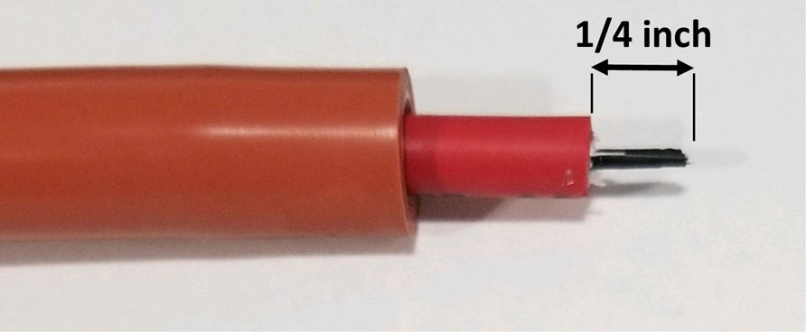
If you're using the style of crimping tool shown below . . . Crimp 1. The outer insulator should be crimped using #1 jaws. Crimp 2. The center conductor should be crimped using the #2 jaws. It's really not important to crimp in this order. Just make the crimps tight. If you don't have a crimping tool like this, try to make the crimps look similar and tight. The videos below will help explain this process. 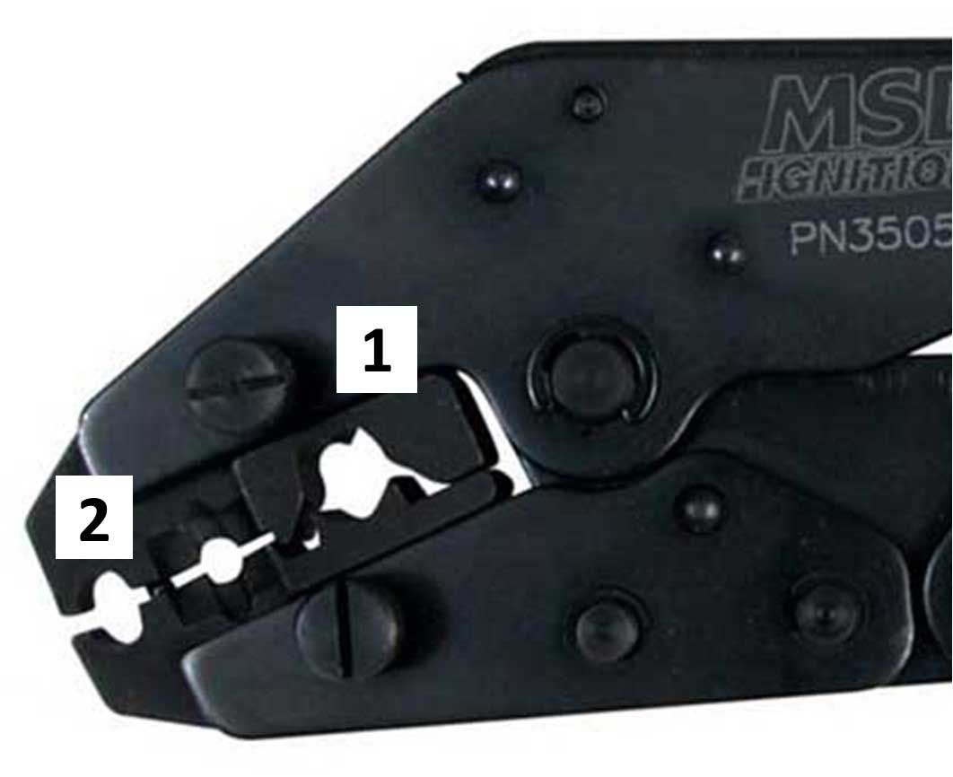
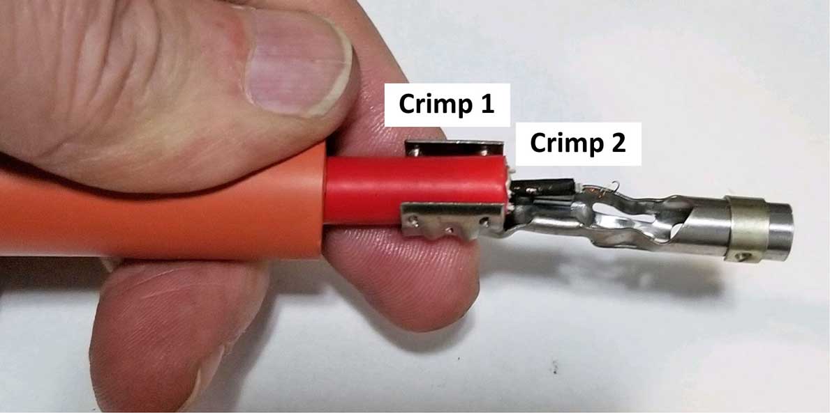 Make certain the center conductor is tightly crimped. 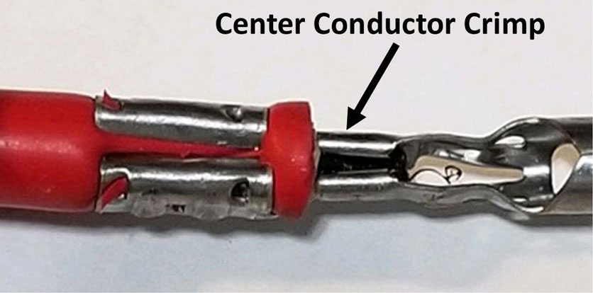 Place a spark plug into the terminal. Feel how the conductor end snaps into place on the spark plug. I suggest that you smear some dielectric grease, silicone grease or other non-conductive anti-seize paste on the porcelain part of the plug or inside the boot. Using such grease there is a very good idea. It can help to keep the plug porcelain from sticking (seizing) to the inside of the silicone boot after a bunch of heat cycles. 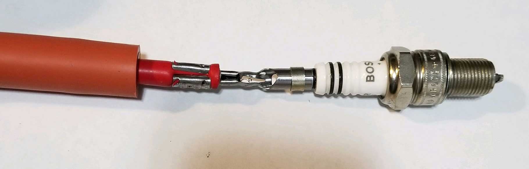 Then carefully pull the wire from the back of the boot and push the spark plug to move the terminal into a good place. If you accidentally pull it too far (you probably will at first), just push it back in.  Now for the optional thermal sleeve going over the wires. These are not required, but I like them. If you're adding a thermal sleeve, make sure to do it before adding the boot on the OTHER end. Cut a piece of sleeve that will be roughly about 1/2 inch short of touching the boots on each end. I prefer to then use about 1.5 inches of dual wall heat shrink tubing at each end to anchor the sleeve ends. You can put the thermal sleeve over the wire using your water based cleaner to lubricate. Then place the heat shrink tubing over it. Then after you complete your terminal and boot assembly on both ends you can and shrink the heat shrink down. 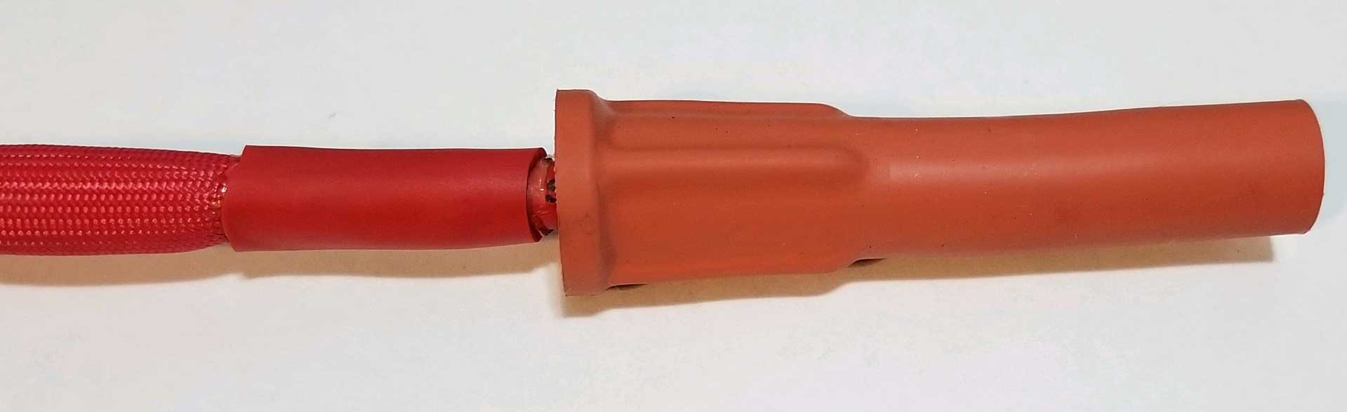 DISTRIBUTOR WIRES Distributor End Again, I like using a water based cleaner as a lubricant, such as Simple Green, when pushing the wire through the boot. Some MSD videos suggest that you can push the wire through the boot with or without the terminal installed. That's up to you. For these photos, I installed the terminal after inserting the wire through the boot. I prefer dual wall heat shrink tubing, because dual wall has glue inside, which melts with heat. 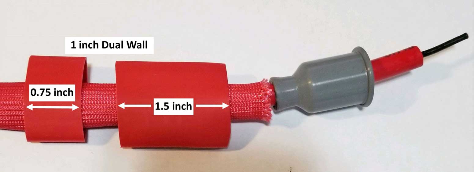 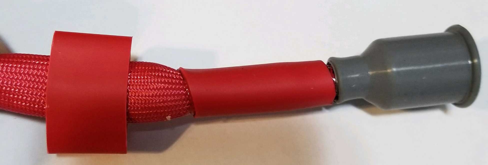
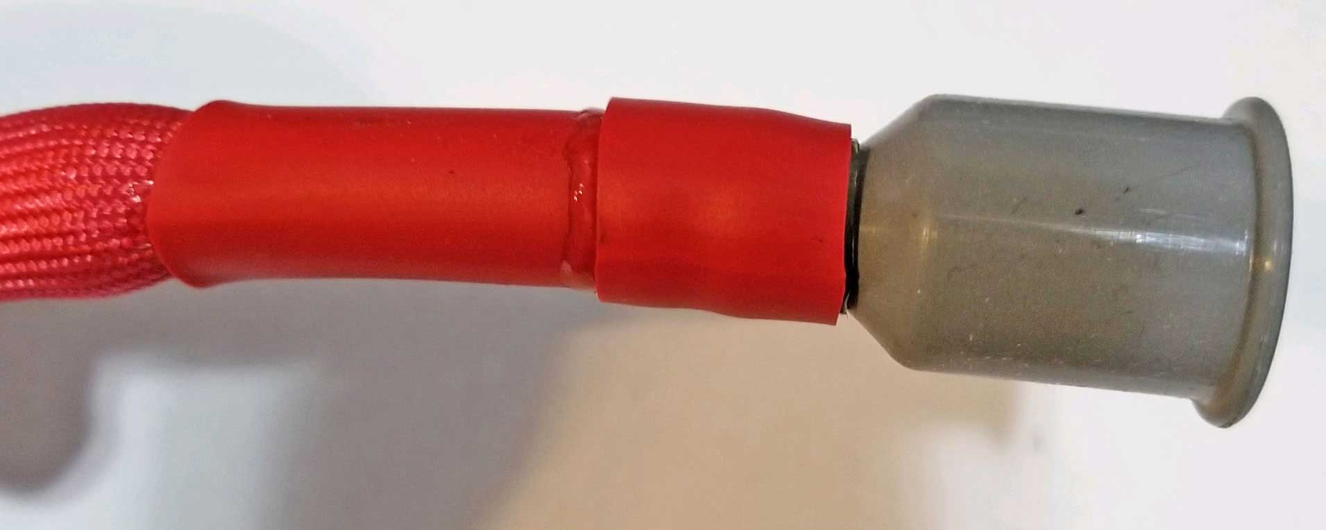 The 1.5 inch long piece of heat-shrink will be enough to hold the sleeve onto the cable. The extra 0.75 inch piece holding the boot is not required and is optional. The second photo below shows these wires made without the extra pieces holding the boots. 
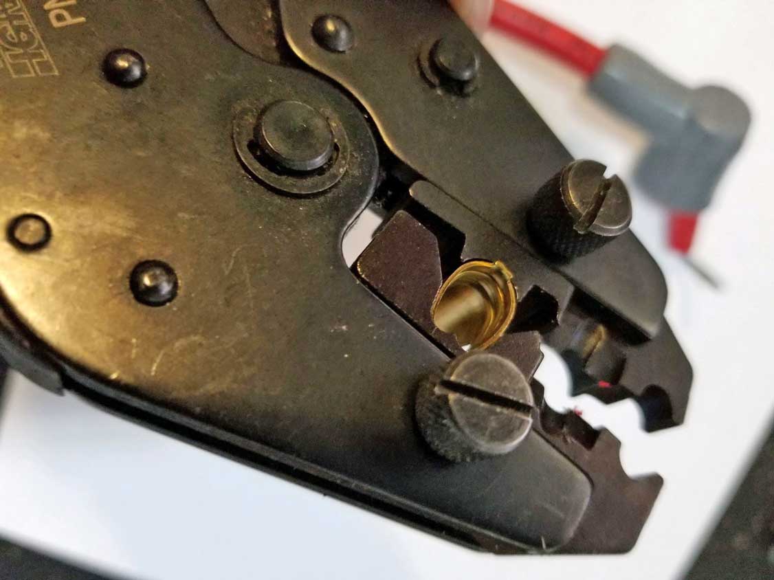
This type of crimp terminal is a "SINGLE CRIMP" style. Make sure to strip off enough insulation (about 1/2 to 3/4 inch), because you must fold the center conductor over and trap it between the terminal and outer insulation. The photo of my crimping tool here shows the proper location to squeeze this terminal. Pay attention to the VIDEOS BELOW if you're a beginner. 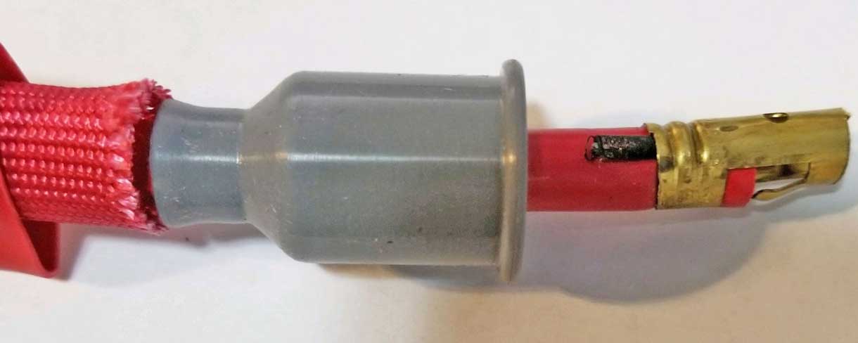
 After crimping, pull the wire back through the boot until it's positioned at the end like this. Try a test fit onto your distributor cap to verify that it feels like a nice fit. 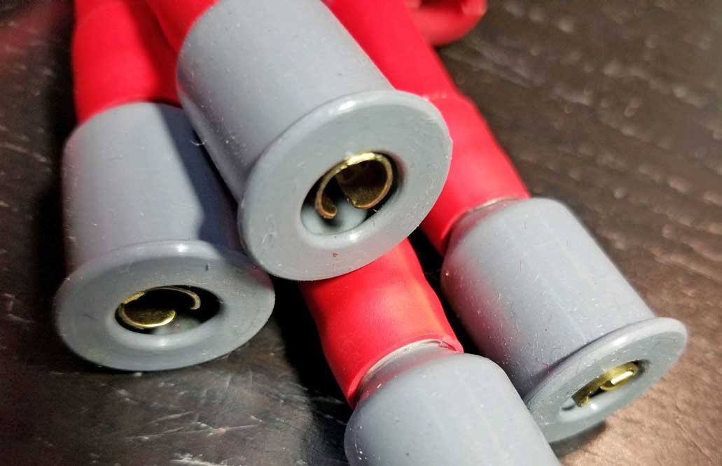 You should mark your cables as you finish each one to help keep them organized. 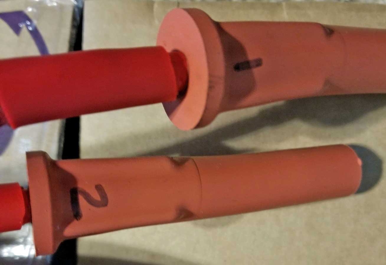
COIL WIRE >> Coil End << OPTIONAL STRAIGHT COIL BOOT These instructions show a 90 degree boot, but if you prefer and install a straight boot for your coil, let me know which one works best for you on a 240 and I'll add that here. Also if you have a coil that's mounted somewhere else in the engine bay (other than the left fender), I'm interested in the wire length you used. Your comments are welcome. I chose this MSD 90 degree COIL boot (PN 3331) for the coil because it fits well on a stock 240 coil mounted in a stock location on the left fender. The larger opening on this 3331 boot is 15 mm. The large end opening for the SMALLER 3321 boot is 14 mm. Both boots are flexible silicone. If you'll be doing the same thing on the coil regarding the thermal sleeve and heat shrink, again, don't forget to slip this on before adding boots to both ends.  When you're ready to add the coil boot, again you'll need to lube it up good. Then insert the wire into the rear of the boot and bring it out the front a couple of inches. You might need to resort to forcefully pulling the wire through with pliers, so you should probably make this wire ONE INCH LONGER so you can cut off the end if it's damaged. Strip about 1/2 to 3/4 inch of insulation.  This type of terminal is a "SINGLE CRIMP" style. You must fold the conductor over and trap it between the terminal and insulation.
 This is the proper location on this crimping tool to squeeze this terminal. Pay attention to the VIDEOS BELOW if you need guidance.
 This terminal is made for multiple angles. Use some pliers to bend the terminal 90 degrees. Make sure to lubricate, then carefully pull the wire back through the boot until the terminal fits as shown. Then you can finish with the heat shrink on this end. 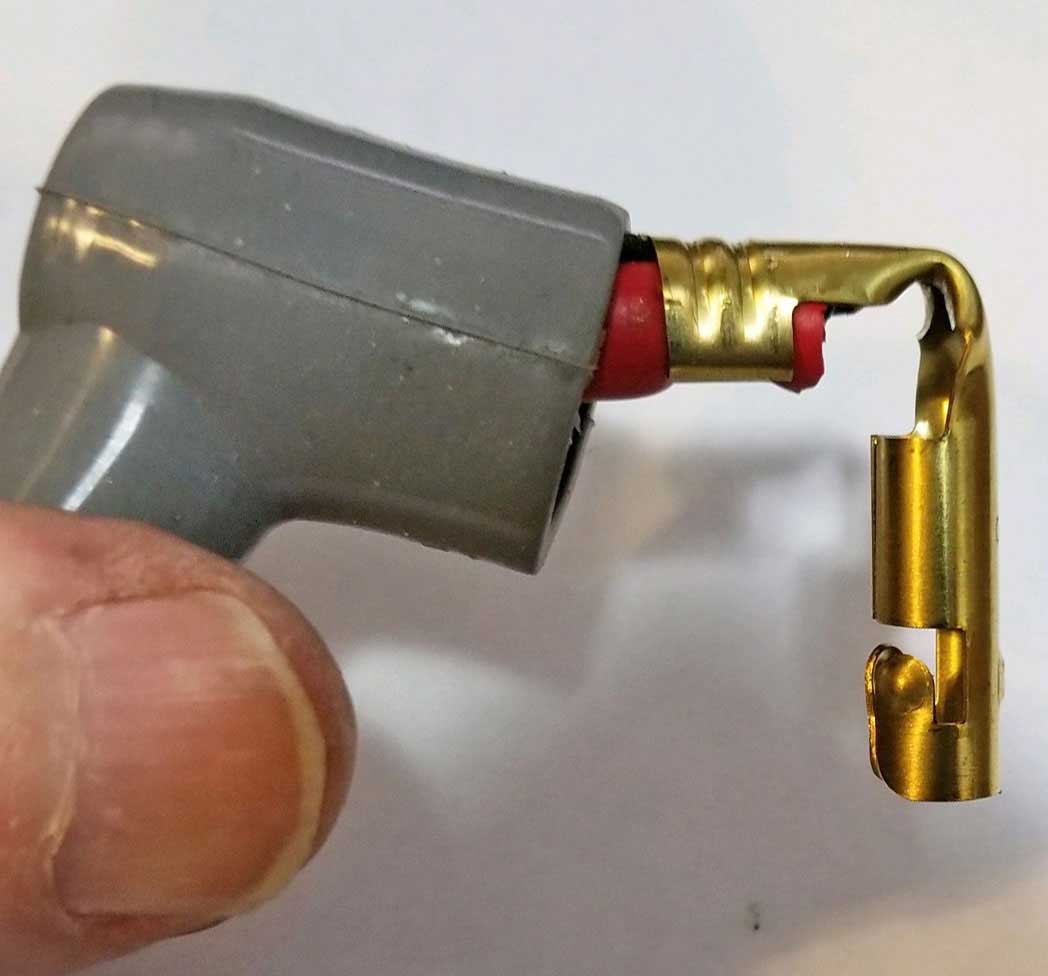
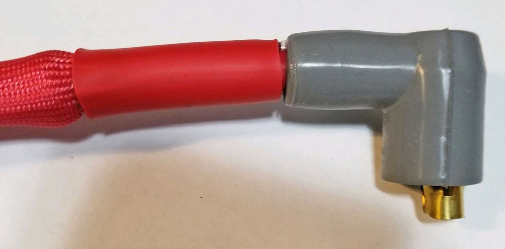 For the distributor end of the coil wire, if you plan to install a straight center distributor boot (3322) as I preferred, use the installation guide above for the straight distributor boots. If you plan to install a 90 degree center distributor boot (3321) the installation technique is the same as the 90 degree boot installation shown above.
The plug boot thermal sleeves are optional and can be added at any time AFTER the set is completed. They simply slip over the plug boot. 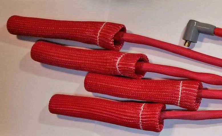 TESTING YOUR WIRES for RESISTANCE This is optional. If you have an Ohm Meter you can test the resistance of your new wires to verify they're good. The second video below discusses this in detail. According to MSD, acceptable max resistance should be about 50 Ohms per foot of wire (holley.com/plug_wire_troubleshooting/). QUICK SHORT VIDEO HERE https://youtube.com/shorts/8h9npLPTJUE?si=1DrBpPkVxYtUvZCW Here are a couple videos on assembling these parts.
MORE RESOURCES AND PARTS MSD Plug Wires and accessories (Holley). https://www.holley.com/spark_plug_wires/ Moroso Plug Wires and accessories. https://www.moroso.com/spark+plug+wires Taylor Spark Plug Cables and accessories. https://pertronixbrands.com/taylor-cable Ton's Performance Spark Plug Cable Accessories https://tonsperformance.com/ |
||||||||||||||||||||||||
| 240 IGNITION (key) Switch Info |
| There were two different ignition switches made for the North American 240 between 1975 and 1993. PN 9203247 for 1975-1989 240 (USA, Canada). PN 9447805 for 1990-1993 240 (USA, Canada). The later one was an updated design using more circuits to accommodate SRS Airbag cars. These two switches are reported to be not interchangeable. Probably, this means not directly interchangeable, however I think would be possible to use a later switch in an early car, with the understanding that you may need to make some modifications to wires. Broader info for 240 dash wiring can be found in my large collection of PIN FUNCTION DIAGRAMS located here. . Ignition Switch 9203247 for 1975-1989 240. 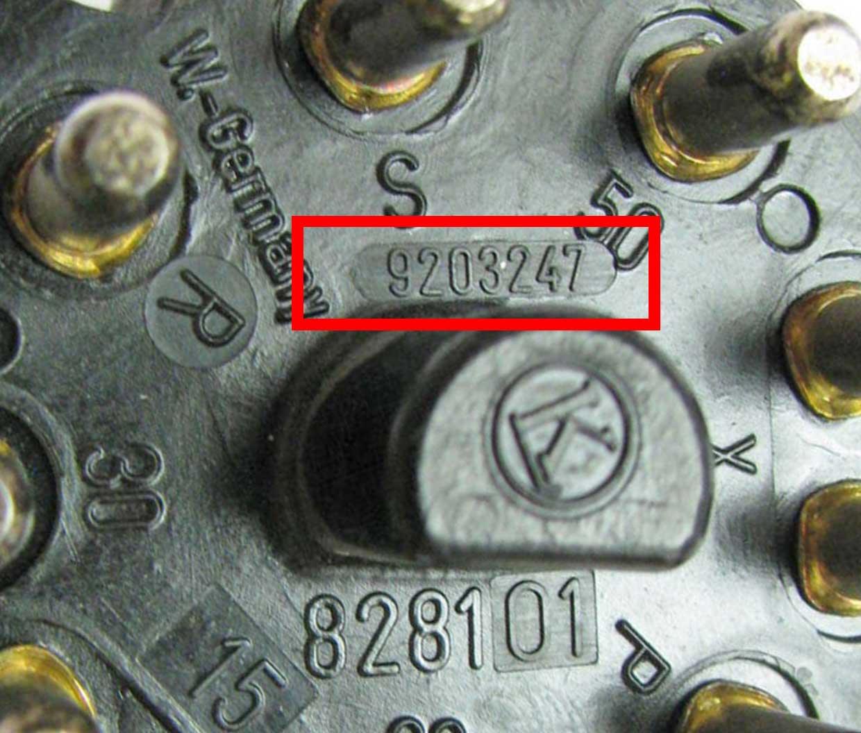
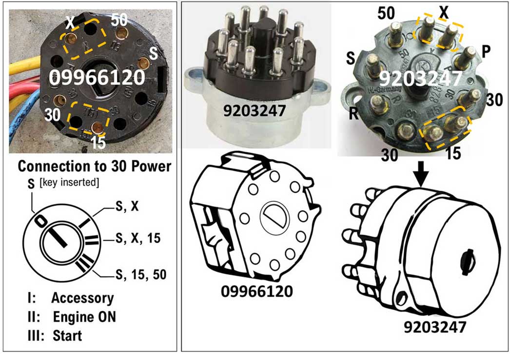 Housing marked 09966120 female receptacle 1975-89 240: The image above and below shows the RECEPTACLE or SOCKET for the ignition switch, which is found in the dash. This receptacle is part of the dash harness in a 240. This same part housing (with same embossed part number on the housing) was used for all 240, 740, and 940 models, however the actual number and arrangement of the circuits and wire colors varied for different models. For the 1975-89 240 this receptacle has 5 pin circuits mating to the ignition switch, which are detailed below.  This 09966120 receptacle pictured above came from a 1984 240 dash harness. Ignition Switch 9447805 for 1990-1993 240. 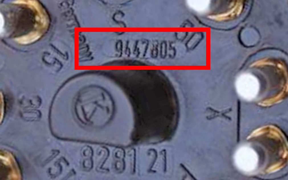
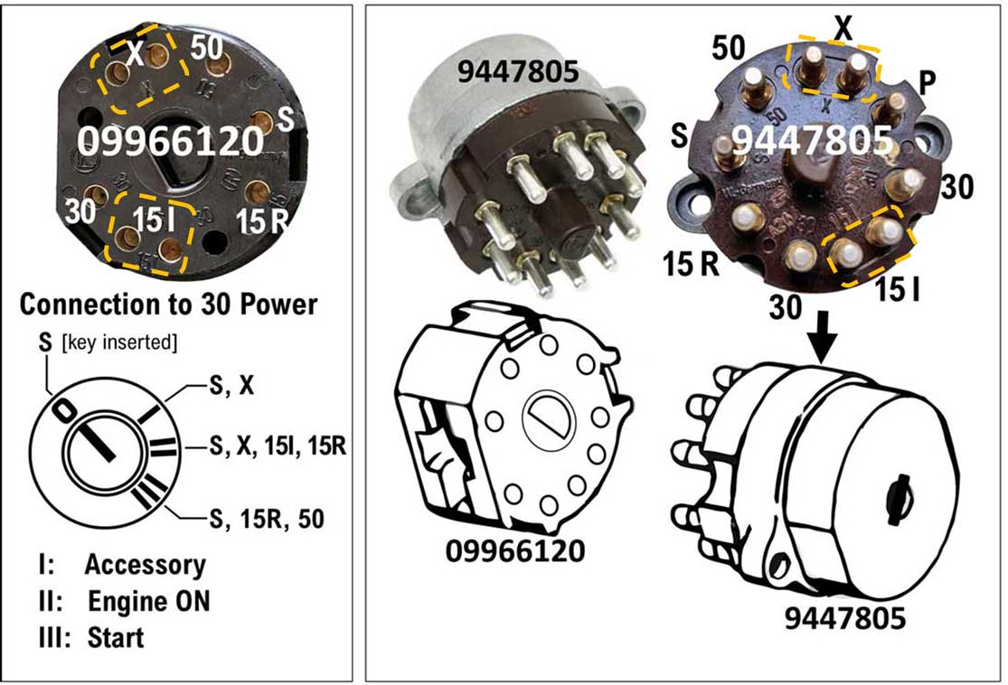 Housing marked 09966120 female receptacle 1990-1993 240: The image above and below shows the RECEPTACLE or SOCKET for the ignition switch, which is found in the dash. This receptacle is part of the dash harness in a 240. This same part housing (with same embossed part number on the housing) was used for all 240, 740, and 940 models, however the actual number and arrangement of the circuits and wire colors varied for different models. For the 1990-93 240 this receptacle has 8 pin circuits mating to the ignition switch. These are detailed below. 
Connected to dash wire harness. These images are of a North American import 1984 240. This style of connector housing is obsolete and no longer available. There's a newer version BELOW. 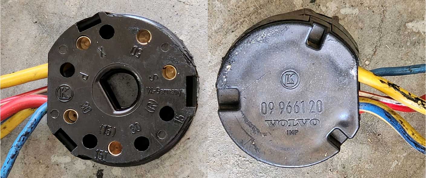 UK or European Versions: These photos below were found in eBay. The left image is from a UK 240 (unknown year). The right one is from a UK 740 (unknown year). While the housing is always the same, the arrangement of pins can change. 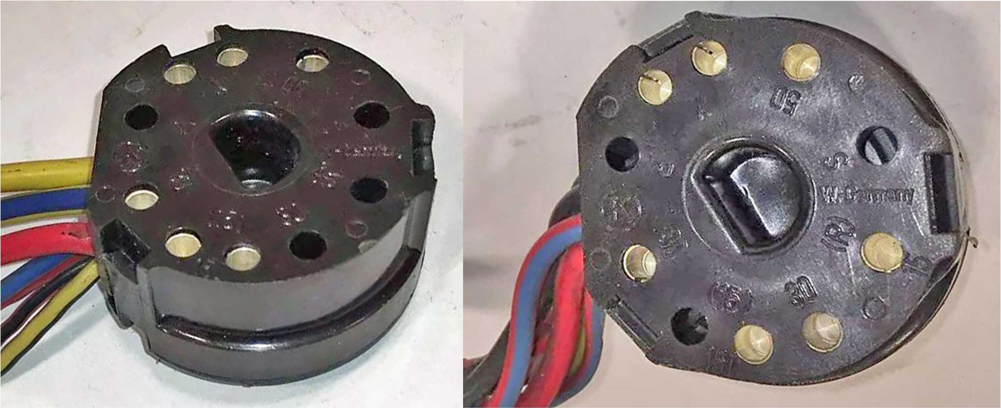 Available Replacement Receptacle Housing. The above style receptacle housing is no longer available. This one below still seems to be available (for now). Volvo 3544771, 3544772: for 240 1988-93 (see below), 740 to 1984, 740 1991-, 940 1991-98, 960 S90 V90 1991-98. https://www.gcp.se/en_eur/products/3544772 https://vp-autoparts.com/en/artiklar/socket-housing-9.html https://vp-autoparts.com/en/artiklar/cover-14.html 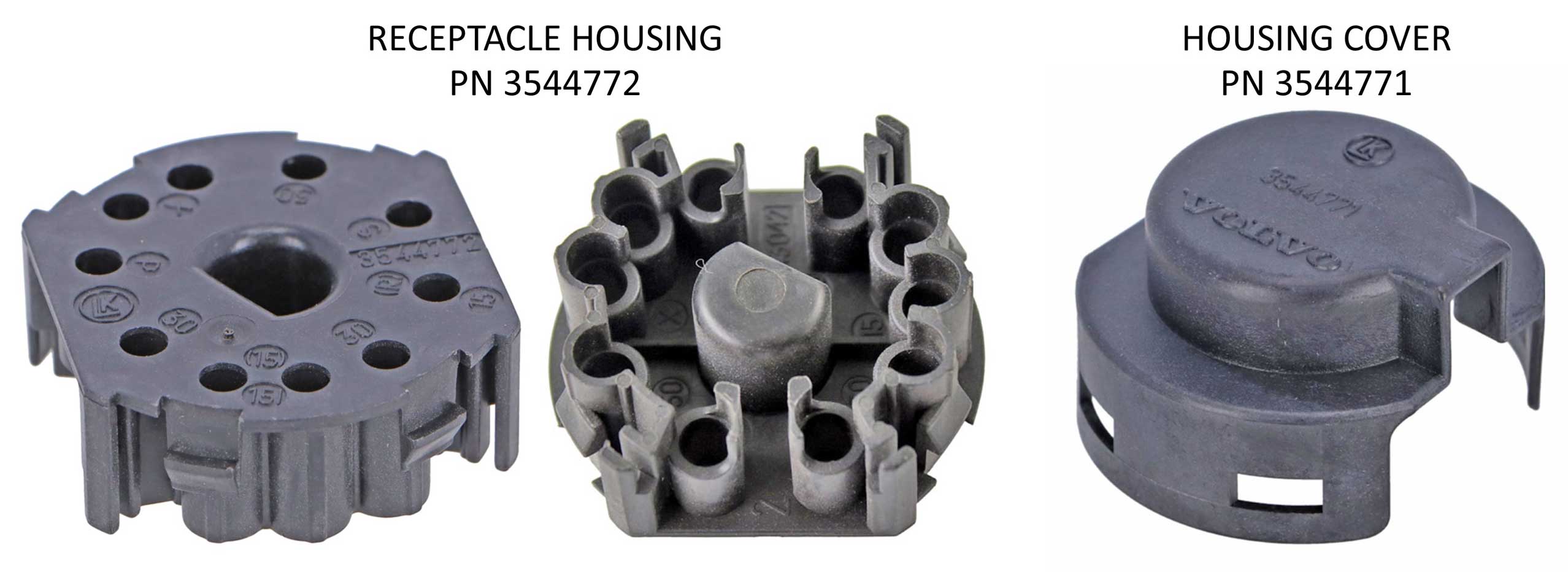 While the above description says this housing is for 1988-93 240, I see NO reason why it won't also work for an EARLY 240. Here's a photo of one on ignition switch 9203247 for 1975-1989 240 (USA, Canada). 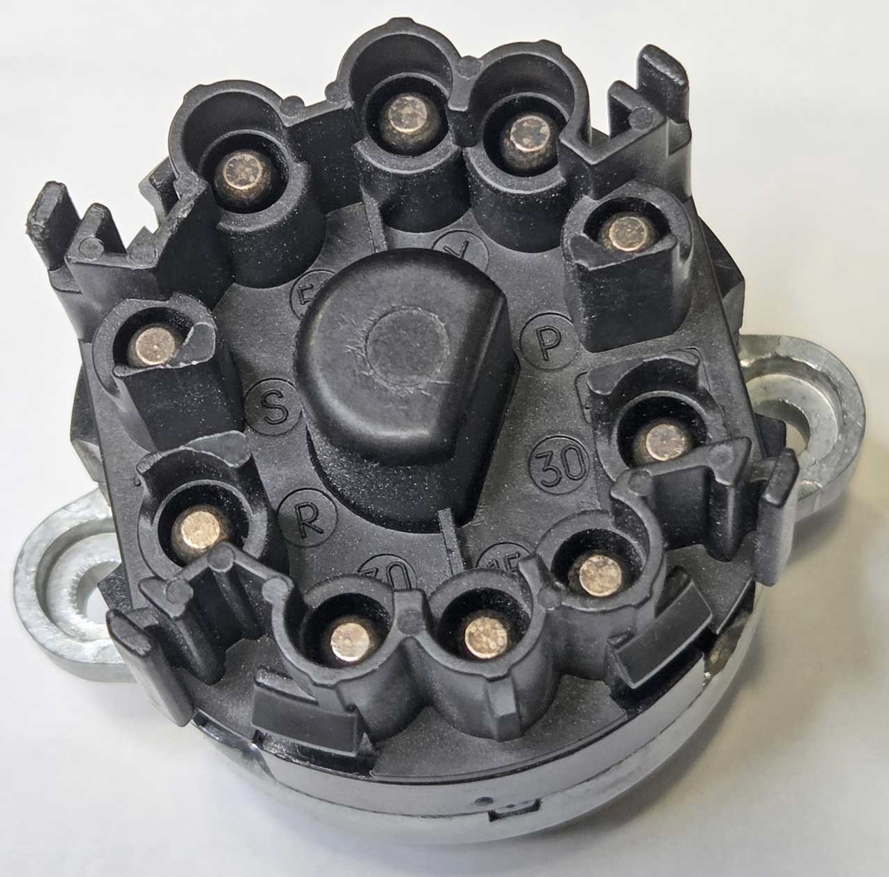 The terminals needed are special silver plated 4 mm female bullet pieces which require soldering. They're not so easy to find. They can be sourced in Europe as Kostal RK 4 L90. They can also be found as Porsche PN 999 652 376 12, which used them for ABS receptacle housings. 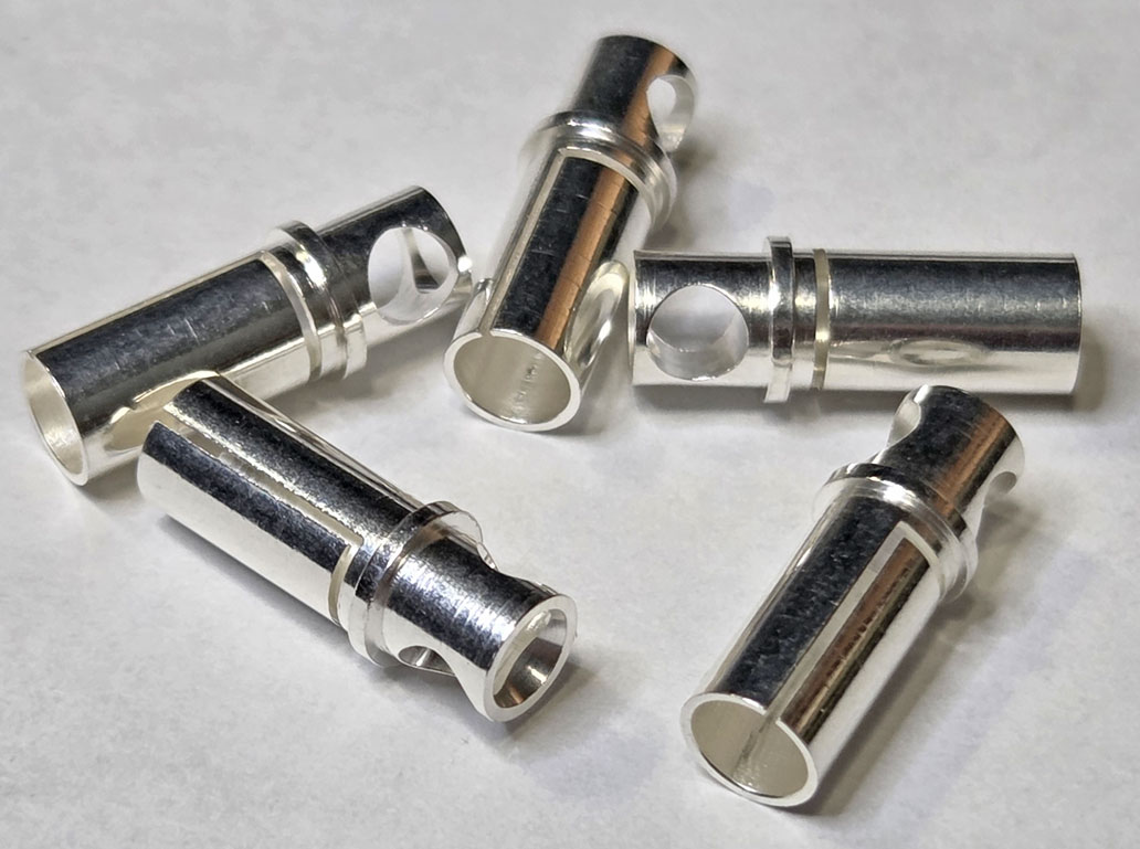 Coincidentally, these are the same terminals used for the ABS connector below in later 240s and 740s. And they're used for the same thing in Porsches of the same era, found as PN 928 612 423 00 for the ABS house and 12 terminals. 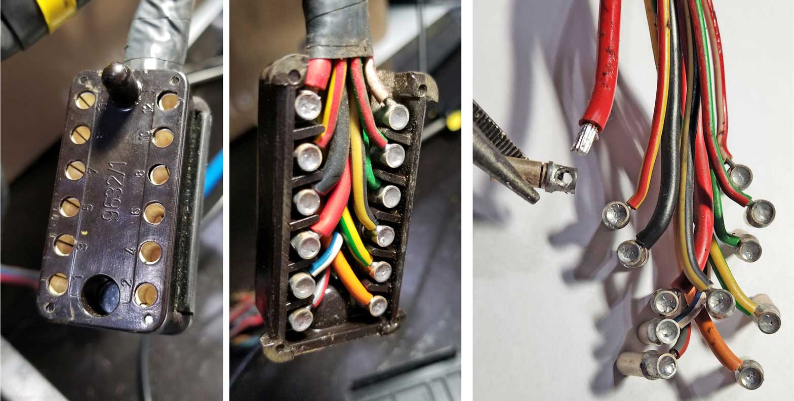 And certainly they can be reused by de-soldering them if you can find a Volvo ABS salvage parts source. |
|||||||||||||||||||||||||||||||
|
|
||||
| davebarton.com |
prancingmoose.com |
240turbo.com |
Special Emblems |
|
| Prancing
Moose Stickers |
Volvo
Stickers |
Body/Chassis/Engine
Labels |
240 MODS and FIXES Page | |
| Other Car Brand
Stickers |
Steering
Wheel Labels |
Center Cap Labels/Overlays |
Cool Volvo
Products |
|
| Grill Labels/Overlays |
Volvo Wire
Harnesses |
Conversion Harnesses |
Harness
Parts/Connectors |
|
| Volvo Relays |
Coil Repair
Harnesses |
240 Window
Scrapers |
740/940
Window Scrapers |
|
| Adjustable Voltage
Regulators |
Horn Buttons |
240 Odometer
Repair |
740 Odometer
Repair |
|
| Volvo Gauge
Faces |
740
Turbo/Boost Faces |
240 Black Door Vinyl |
850 Odometer
Repair |
|
| ALTERNATOR Page |
240 Power Mirrors - Switches |
240 Oil Cooler Page |
240 Fuse Panel Page |
|
| Group A
Racing 242 Turbo Page |
240 Hydraulic Clutch | Fuel Pump RELAY Page |
240 Headlight RELAY Page |
|
| Used Parts & Extra Stuff for sale |
CRIMPING Page |
240 Ignition Page |
240 Headlight Page |
|
| 240 Gauge Electrical Diagrams | 240 REAR END Page | Yoshifab Catch Can Install | 240 TAILLIGHT Page | |
| Side Marker
Lights Page |
Gentex Mirror Upgrade | Yoshifab Drain Tube Install | Modified 240 Favorites | |
| SoCal Salvage Yards | Unleaded Racing Fuel | B26FT Stroker | Dave's 245 Spec Page | |
| 240 SUSPENSION Page | 240 Lowering Page |
240 Windshield Page |
240 WIPER Page | |
| 240 BRAKES Page |
240 Dash Top Gauge Pod | Cadillac 4-Note Horn Install | 240 DYNAMAT Installation | |
| 4 Speed Fan
Controller |
Electric Cooling Fan
Page |
BRUSHLESS Cooling Fan Page |
Tropical Fan
Clutches |
|
| 240 AC Page | "KOMFORT BLINKER" Upgrade | T5 Trans Conversion Page | 240 Engine Mount Page | |
| 240 VIN Page | Stepper Idle Valve Page |
Vacuum Diagrams | 240 HOOD Page | |
| 240 Exhaust Page | 242 Power Vent Window Project |
EFI Volvo Pin Function Diagrams |
Favorite Links | |
| R-Sport
Apparel |
Prancing
Moose Apparel |
Volvo Meet Photo Albums | Texas Volvo Meets and Events | |
| Ordering Instructions | Policies | PAYMENTS Page |
Mojave Road Trail Map Page |
|
| Returns | Shipping | Shopping Cart Troubleshooting | Contact Us |
|

|


alternators are known for poor voltage.")


