|
2 4 0 T U R B O . C O M D A V E ' S V O L V O P A G E
|
||||||||||||||||||||||||||||||||||||||||||||||||||
|
2 4 0 T U R B O . C O M D A V E ' S V O L V O P A G E
|
||||||||||||||||||||||||||||||||||||||||||||||||||
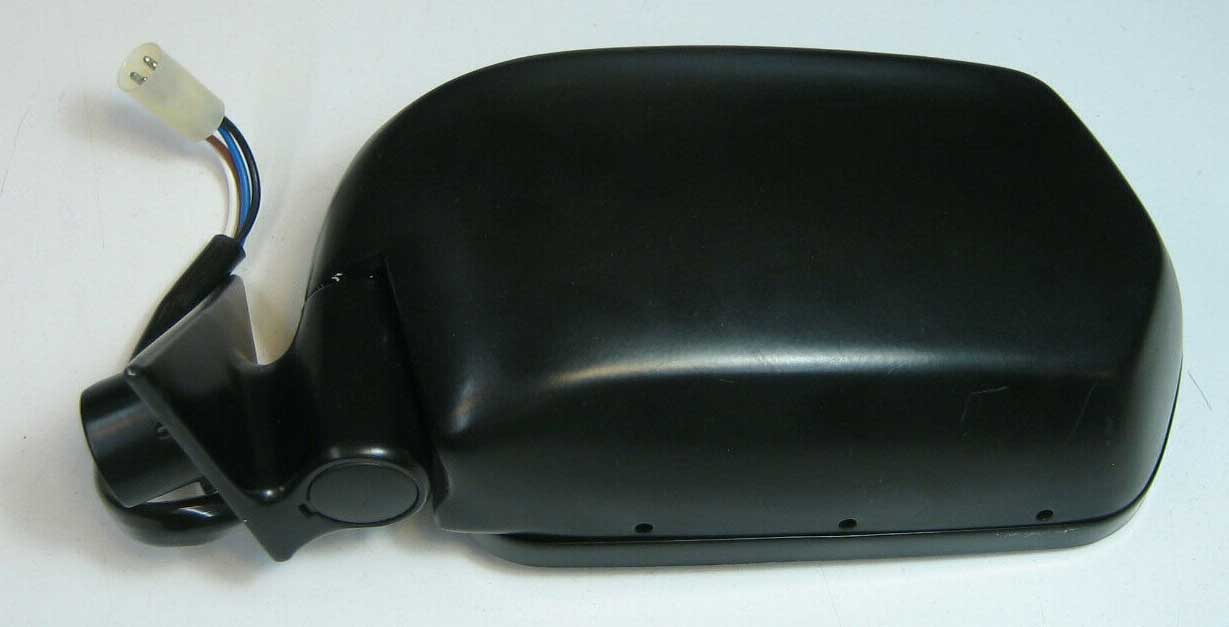
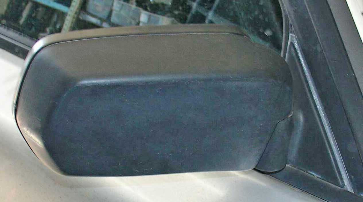
EARLY POWER MIRRORS The first early version shown below (Alternate 1) came along prior to 1975 and were an option or accessory on 140, 160 and early 240 models. These mirrors might be found from the factory on upscale models, such as the 260 series. The second early version (Alternate 2) became the next visual styling change. This power mirror was used from approximately 1979 through the 1985 model year. This version was usually found on 240 Turbo models, some 240 GL models and 260 models. MID-VERSION POWER MIRRORS The visual styling of side mirrors changed again in 1986. These mirrors were a bit larger (with larger glass). For these mid-version mirrors (1986-91), the motor circuitry remained the same as earlier power mirrors and they used the same switches as early power mirrors. These mirror were NOT equipped with heated glass, like the late mirrors. Also this 1986-91 period had a part number division for the 240 mirrors and some parts. The division for 244 models was before/after chassis number 378164. For 245 models the division was before/after chassis number 840616. This division occurred during the 1989 model year. The physical changes to these mirrors during this division are not known. LATE POWER MIRRORS The late version power mirror was offered for the 1992-93 240. The exterior design of the late mirror looks the same as the 1986-91 mirror, however the circuitry and drive motors changed significantly. New later style switches were also introduced for these mirrors and the wiring order for the switches was changed (early and late switches are not interchangeable). Late mirrors also added heated mirror glass controlled separately by a dash switch and relay. |
 
|
||||||||||||||||||||||||||||||||||||||||||||||||||||||||||||||||||||||||||||||||||||||||||||||||||||||||||||||||||||||||||||||||
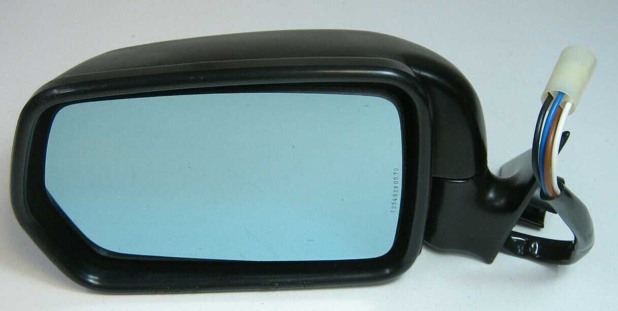    
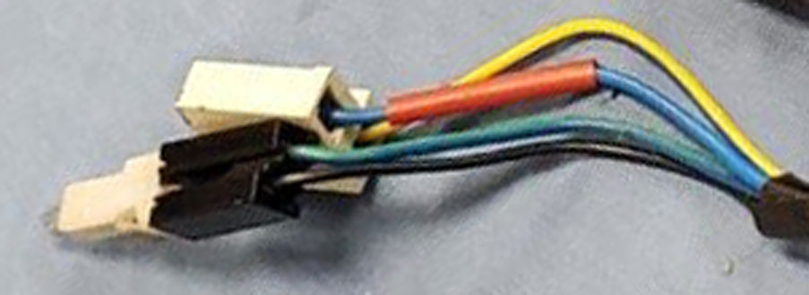
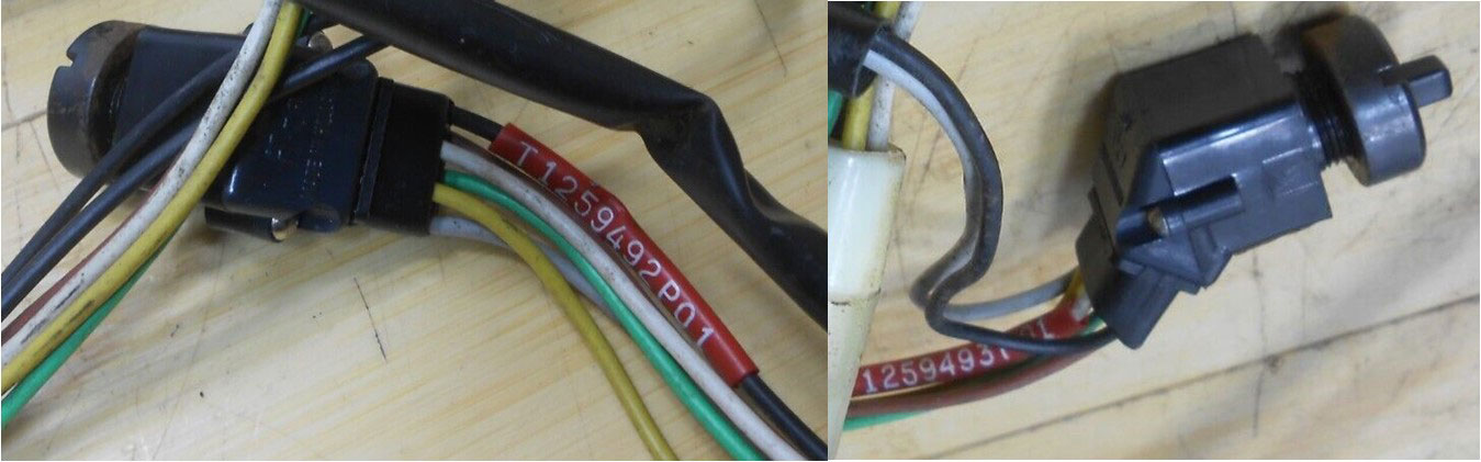 Harness part numbers can be found on a red tube on a wire near the switch connector. A separate switch harness is used for each mirror. .
|
|||||||||||||||||||||||||||||||||||||||||||||||||||||||||||||||||||||||||||||||||||||||||||||||||||||||||||||||||||||||||||||||||||||||||||||||||||||||||||||||||||||||||||||||||||||||||||||||||||||||||||||||||||||||||||||
 A Mid power mirror for 1986-91 is visually identical to a late mirror, except this Mid mirror uses an early style ROUND HARNESS CONNECTOR (4-poles), same one as the early mirrors. And this mirror uses an EARLY mirror switch. Also this mirror does NOT have heated glass. That was in a late mirror only. Mid-power mirrors had a part number change that was divided by chassis number, so there was some sort of change during the 1989 year. That change is not known. 1986-91 244: The division/change was before or after chassis number 378164 (occurred mid-1989). 1986-91 245: The division/change was before or after chassis number 840616 (occurred mid-1989).
 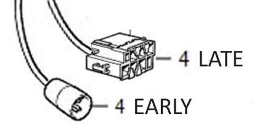
NOTE: Mid Mirrors found on 1986-91 240 used early style ROUND 4-pole plugs and used EARLY mirror switches PN 1235091. Late Mirrors found on 1992-93 cars used SQUARE 6-pole plugs and used LATE mirror switches PN 3540358.
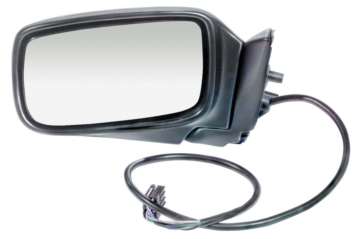
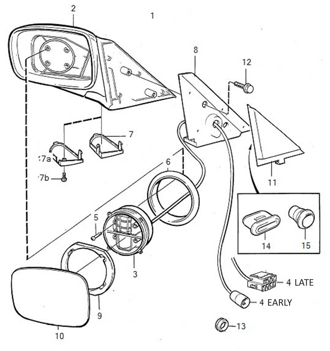
If you're buying or assembling a LATE 240 mirror kit (1992-93), these images below will help you make sure you have it all. 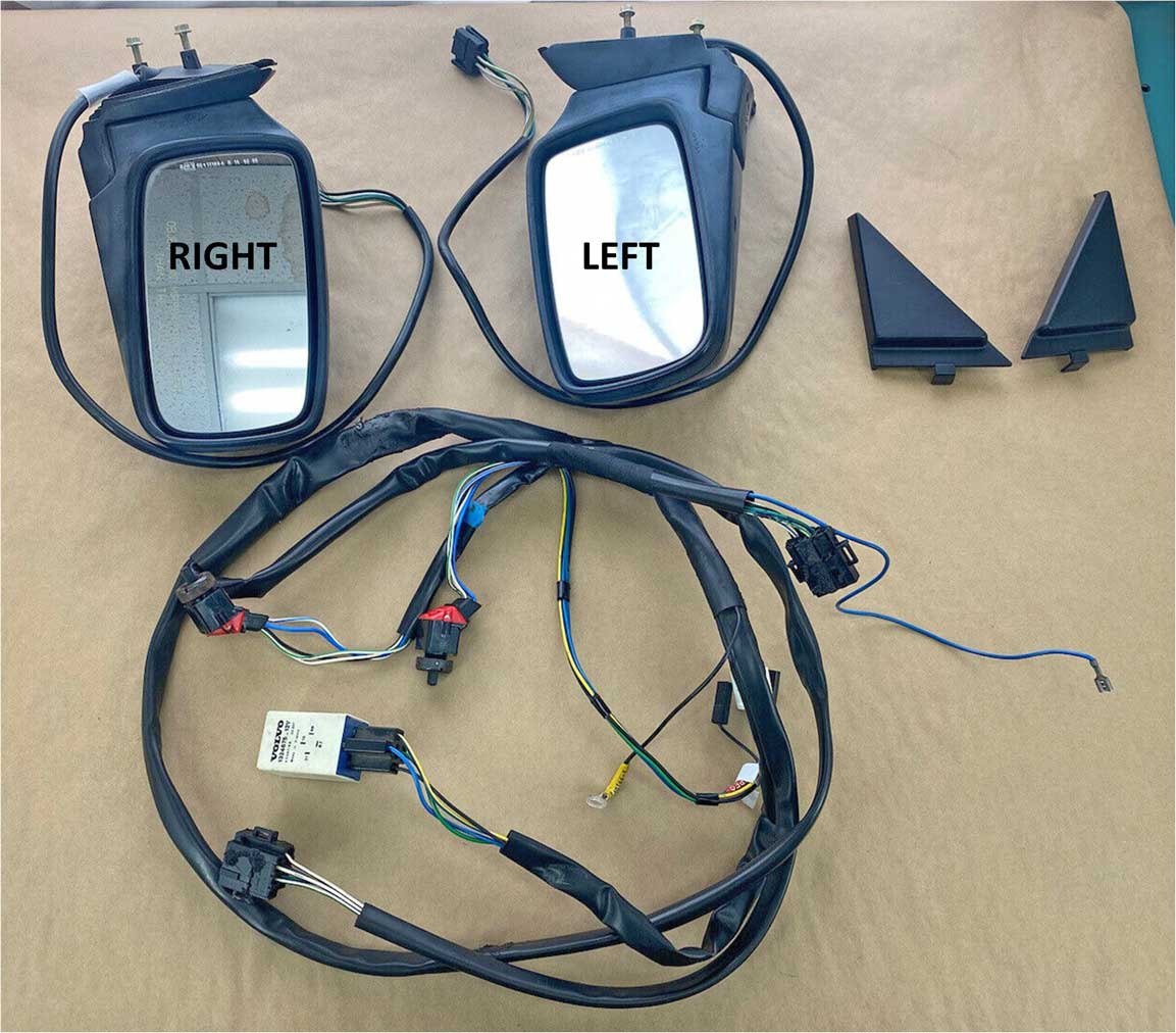  . 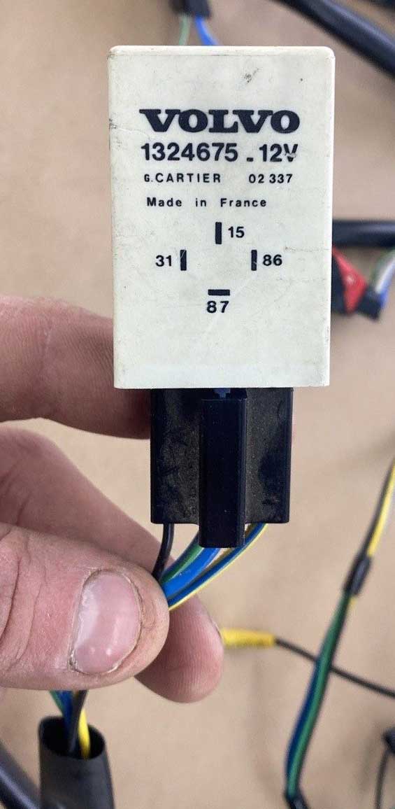 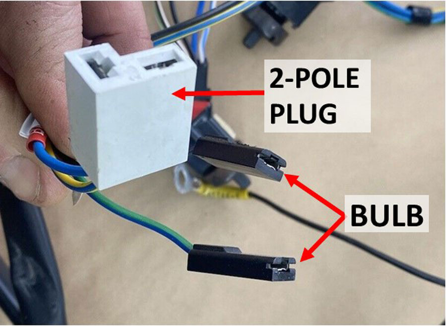 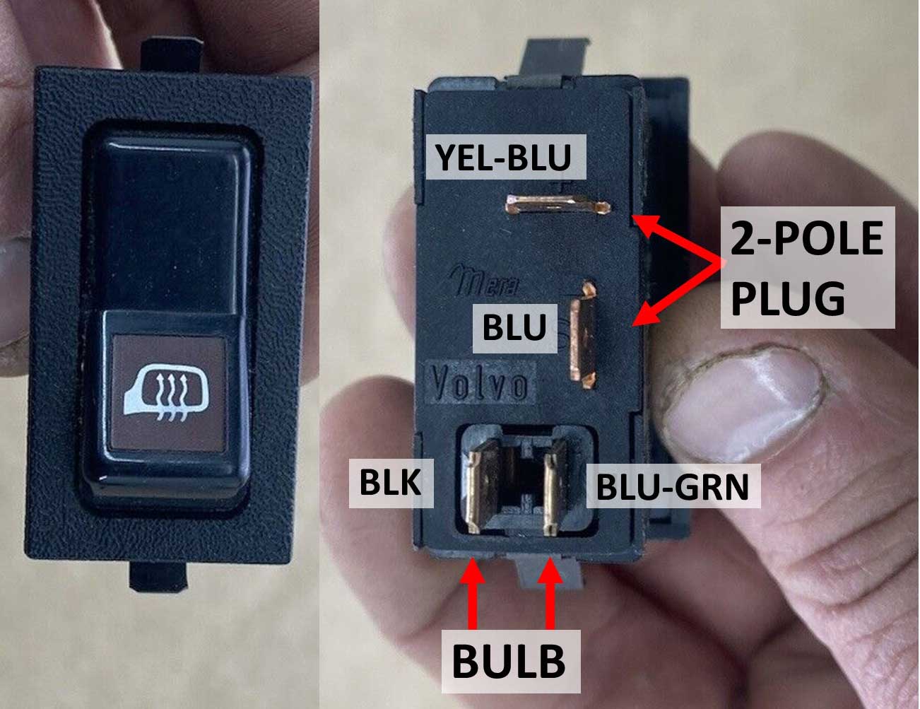 |
|||||||||||||||||||||||||||||||||||||||||||||||||||||||||||||||||||||||||||||||||||||||||||||||||||||||||||||||||||||||||||||||||||||||||||||||||||||||||||||||||||||||||||||||||||||||||||||||||||||||||||||||||||||||||||||||||||||||||||||||||||||||||||||||||||||||||||||||||||||||||||||||||||||||||||||||||||||||||||||||||||||||||||||||
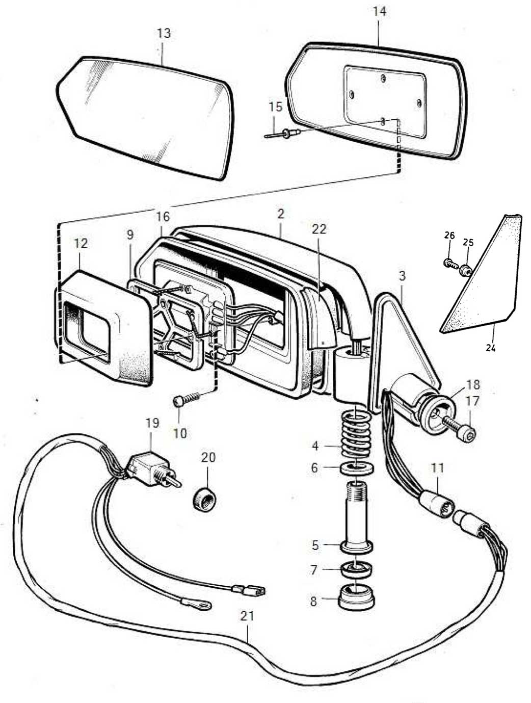
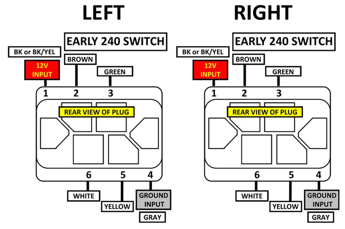
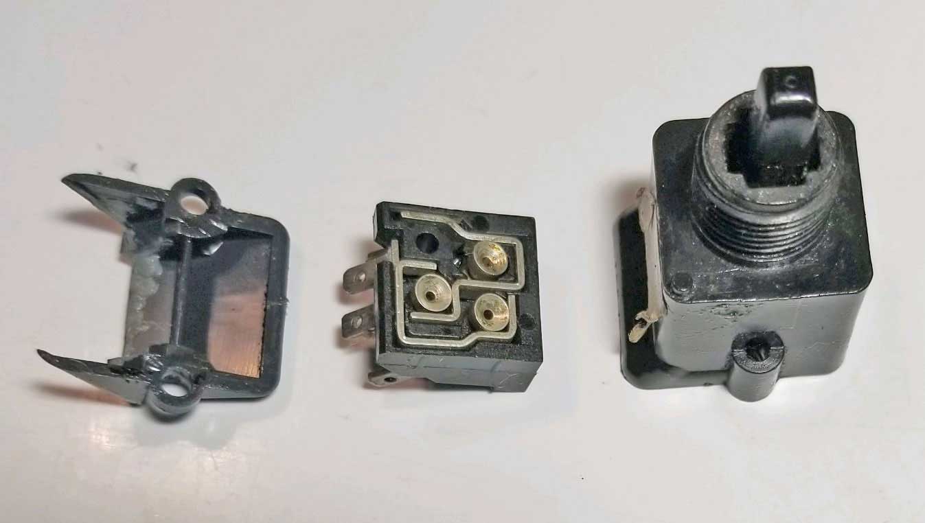
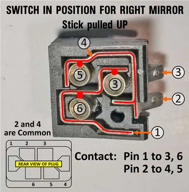
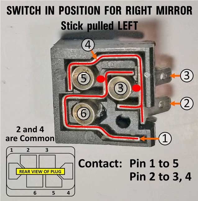
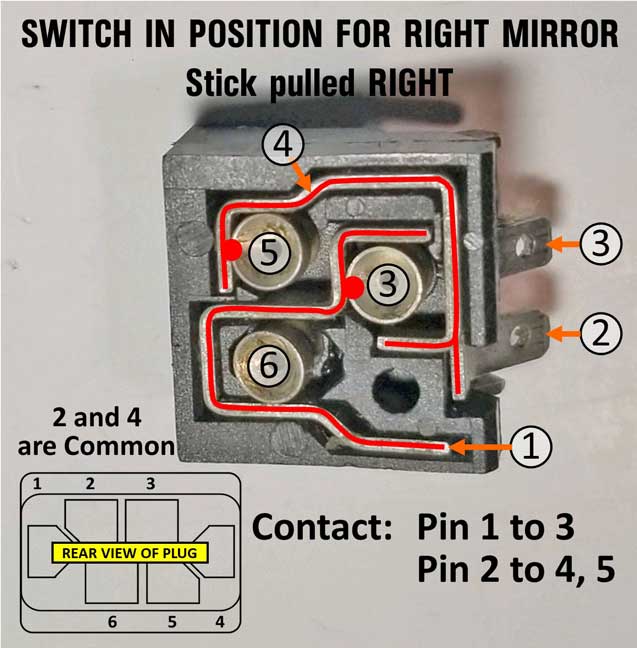
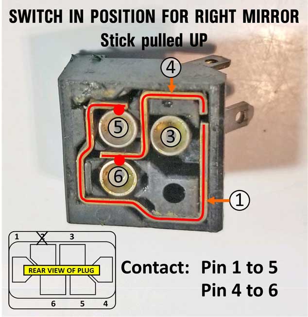
Since there was a serious lack of info available, I decided someone needed to find a way to disassemble these mirrors properly and publish that info. So I acquired a cheap used one which could be sacrificed for the pursuit of knowledge. Why would you ever need to disassemble one of these mirrors? Hopefully you won't need to, but there are a few reasons why you might. The mirror glass could become broken. The internal drive motor unit could stop working. It's replaceable. To begin with, the Greenbook was NOT very helpful.  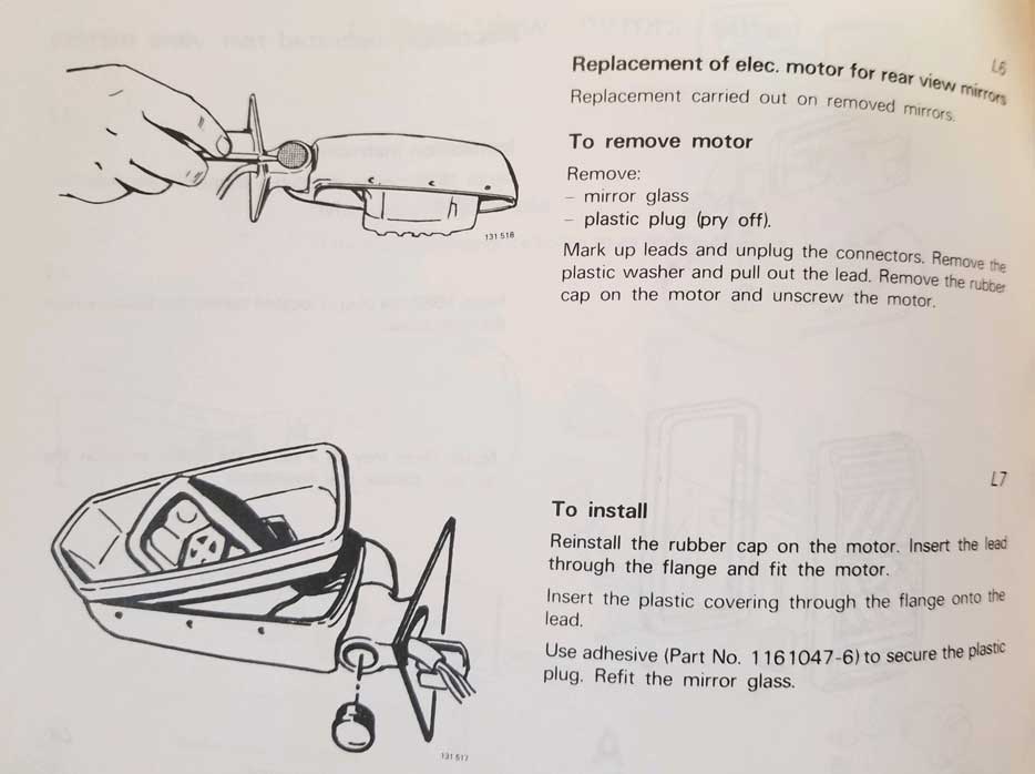 So here are some methods I have found for disassembly. Thank you goes to cleanflametrap for helping with this. If you have trouble getting things apart, I have posted a VIDEO (not mine) further below which may help. The mirror glass is pretty thick and will take a lot of force before it breaks (but it can break). The glass is held onto the backing plate with two sided tape, which you will probably not be able to separate while the backing plate is still attached to the mirror. So I believe it may be necessary to remove the mirror and backing plate as ONE unit FIRST. Before you do that, have a look at the video further below.. 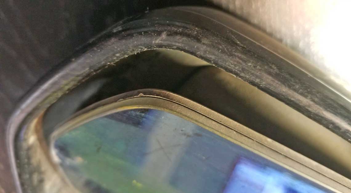 Have a look at these FOUR PEGS on the back of the plate. Those pegs snap into those four holes in the mirror drive motor unit. Removing this mirror/plate is done by pulling it off. You will be pulling it HARD until those pegs pop out. Pay attention to my CAUTIONS below. 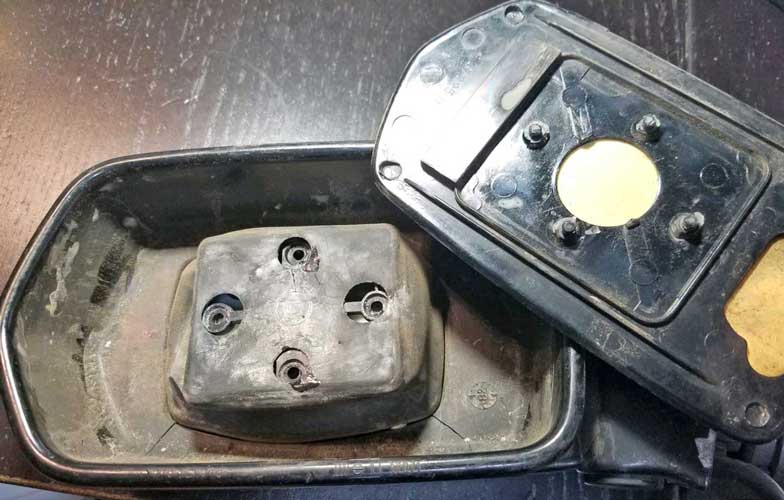 When you pull, make sure you only pull from the TOP or BOTTOM of the mirror. Or alternately from the TOP, then BOTTOM. Keep pulling and alternating until it pops loose. CAUTION: If you pull from the LEFT or RIGHT like I did, you'll probably break the glass, like I did. It may take a LOT OF FORCE to break it free, so don't give up. 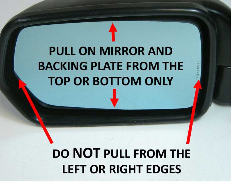 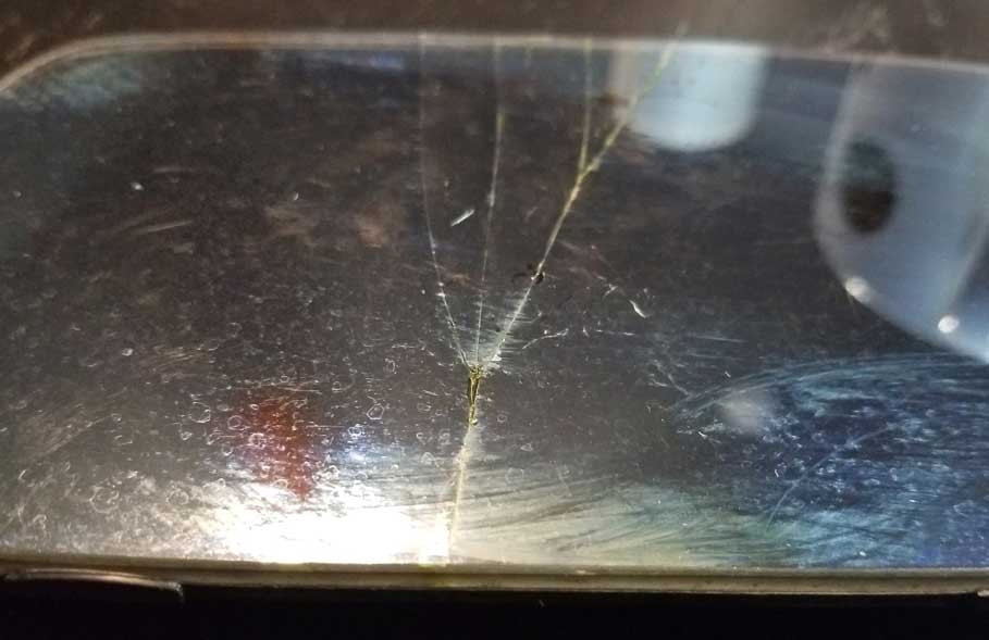 The rubber cover below will be trapped or pinched under the DRIVE MOTOR UNIT around the edges. To remove the two screws holding the drive unit, flex the holes in the rubber cover so you can see those screws. Use a Phillips screwdriver to remove them. Once the DRIVE MOTOR UNIT is loose, the rubber cover will come free. 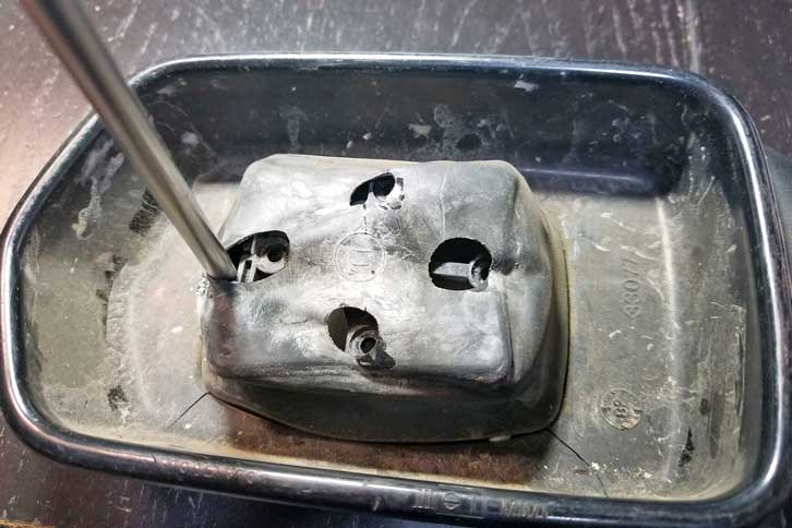 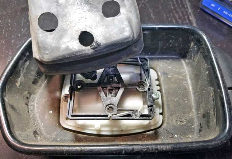 At this point below the inner mirror shell will simply lift out and the DRIVE MOTOR UNIT can pass through the hole in that shell. If you need to replace the DRIVE MOTOR UNIT, there's a 4-pole plug that you'll need to unplug. The plastic corner piece at the top right corner below lifts out to make more room to work with that connector.  Early Electric Mirror Disassembly VIDEO https://www.youtube.com/watch?v=Mwi6nzMsHZ8 EARLY MIRROR ELECTRICAL STUFF I thought I would document some electrical information on this early mirror. I think it'll come in handy. Here's another photo of the DRIVE MOTOR UNIT below. It's flipped over in this image so you can see the other side. This is the side that normally faces the mirror front. I won't be taking this unit apart, but as you can see, there are FOUR wires. Two wires (blue and black) go to the motor inside that large bulge. Two wires (brown and white) go to a solenoid in the smaller bulge. I'll explain more below of what I've leaned about how these four wires make this thing work. 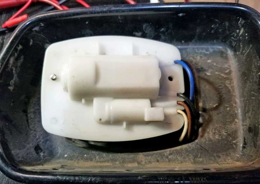 You can refer to the diagram below and follow along. Pin 1 on this mirror switch for an early 240 will always be POWER. Pin 4 for an early 240 will always be GROUND. LEFT-RIGHT: When the switch joystick is pushed LEFT or RIGHT, a power and ground signal is sent to the Drive Motor Unit through Pins 3 and 5. The internal design of the switch allows for the polarity of these signals to be swapped, which allows the motor to run in forward or reverse (for left or right), depending on the direction the joystick is pushed. UP-DOWN: For the UP or DOWN function to work, there's a SOLENOID which receives a power and ground signal through Pins 6 and 2. The ground signal is a constant ground coming through the BROWN wire from Pin 2 of the switch. Pin 2 gets its ground from Pin 4, because Pins 2 and 4 are connected internally. The power signal comes through the WHITE wire from Pin 6. This Pin 6 power signal is activated only when the switch is pushed toward the UP or DOWN direction, because these movements connect Pin 6 to Pin 1 inside the switch, sending power to the SOLENOID. When the SOLENOID is energized by the Pin 6 WHITE wire, it triggers a function change in the Drive Unit mechanism, which changes the RIGHT-LEFT function to an UP-DOWN function. If you listen carefully, you can hear the audible click as the solenoid makes the change. This click can be heard in the below video. 240 EARLY AND MID MIRROR WIRING DIAGRAM For Early Mirrors to 1985 (and also Mid Mirrors 1986-91) 
Click HERE to see testing information for EARLY 240 mirror SWITCHES. It's Time for a VIDEO Volvo 240 Early Power Mirror Function Test The Drive Motor Unit in this Volvo mirror has one motor, which can perform two separate functions. Motor Function 1: LEFT - RIGHT movement. Motor Function 2: UP - DOWN movement. There is a SOLENOID inside the Drive Motor Unit, which switches between the two motor functions. You can hear the AUDIBLE CLICK of the solenoid as the function changes. https://www.youtube.com/watch?=8&v=4JaHF6SgKlk If your work or hobby involves testing stuff like this, a DC Variable Power Supply can be a big help. These can be be found fairly inexpensively as used items on eBay or other places. This one is an old-school analog type that is limited to 1 amp output. I think most available these days will have digital displays. 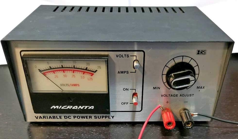 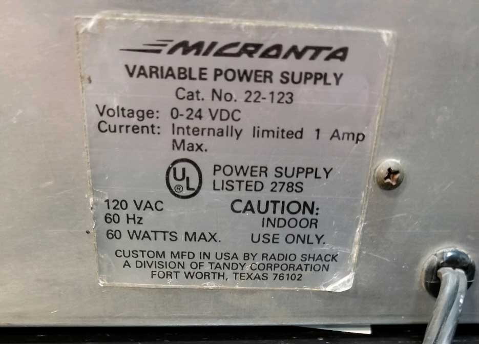 |
These will look a lot like late mirrors, except these will have a round, white 4-pole plug. If you need to disassemble a MID power mirror, removing the glass is the first step. You'll find that the procedure for a MID mirror is the same as a MANUAL mirror.  There will be an access hole on the bottom of the mirror. Using a flat screwdriver, you can reach the white retaining ring and turning it slightly will unlock the glass from the inner mirror mechanism. Here's a view of the electrical mechanism inside a MID mirror.  Here's a video below showing the partial disassembly of a 740 manual mirror, which can help guide you for a 240 MID power mirror. https://www.youtube.com/watch?v=k82IKSrizcg MID MIRROR ELECTRICAL 1986-91 SWITCHES For a description of the functions, you can refer to the diagram below and follow along. Pin 1 on the early mirror switch for a MID 240 will always be POWER. Pin 4 for a MID 240 switch will always GROUND. LEFT-RIGHT: When the switch joystick is pushed LEFT or RIGHT, a power and ground signal is sent to the Drive Motor Unit through Pins 3 and 5. The internal design of the switch allows for the polarity of these signals to be swapped, which allows the motor to run in forward or reverse (for left or right), depending on the direction the joystick is pushed. UP-DOWN: For the UP or DOWN function to work, there's a SOLENOID inside the mirror, which receives a power and ground signal through Pins 6 and 2. The ground signal is a constant ground coming through the BROWN wire from Pin 2 of the switch. Pin 2 gets its ground from Pin 4, because Pins 2 and 4 are common or connected internally. The power signal comes through the WHITE wire from Pin 6. This power signal is activated only when the switch is pushed toward the UP or DOWN direction, because these movements connect Pin 6 to Pin 1 inside the switch, sending power to the SOLENOID. When the SOLENOID is energized (joystick moving UP or DOWN), it triggers a function change in the Drive Unit mechanism, which changes the RIGHT-LEFT function to an UP-DOWN function. If you listen carefully, you can hear the audible click as the solenoid makes the change. This click can be heard in this function video I made in a previous section. 240 MID MIRROR WIRING DIAGRAM 1986-91 (Same function as early mirror. Uses an EARLY switch) |
240 LATE Power Mirrors 1992-93
These will look a lot like MID mirrors, except these will have a rectangular, black 6-pole plug. And of course heated glass. Why would you ever need to disassemble one of these mirrors? Hopefully never. But there are a few reasons you might need to. The mirror glass could become broken. The internal electrical drive motor unit could stop working. And it's replaceable. Volvo Instructions are NOT helpful. Don't attempt to remove the mirror glass like this. IT'LL TURN OUT BAD! You'll see why further below. 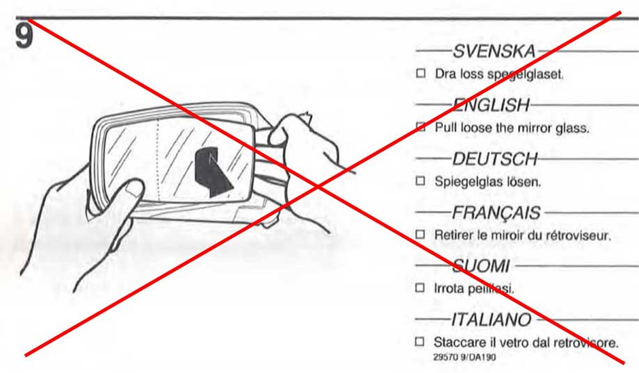 If you're familiar with this type of mirror back BELOW, you should know this LATE 240 POWER mirror is NOTHING like this. This image is what you'll find in a MID-Power Mirror (1986-91) or in a MANUAL mirror. The LATE power mirror is somehow so stupidly different. 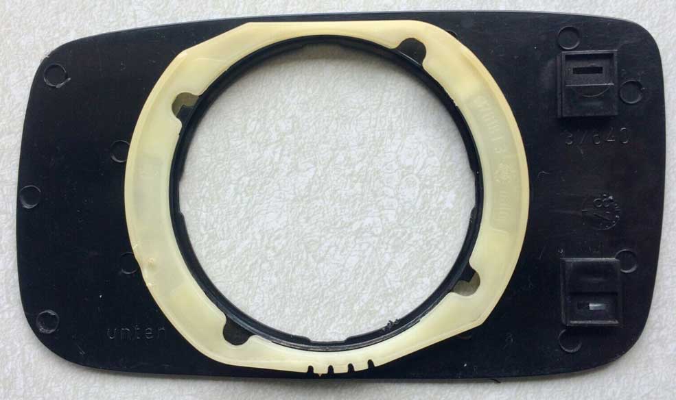 This manual glass above is really easy to remove. You just insert a flat screwdriver into a hole on the bottom of the mirror and rotate that white collar. That hole on the bottom is present on the late power mirror just to confuse you, but it's useless unless you have a manual mirror. Volvo decided instead their LATE POWER mirrors would be stupid and difficult. The LATE 240 power mirror glass removal is exactly the same as this S60/V70 video.
Except DON'T BELIEVE him when he says it's easy to open those clips. Also DO NOT forcibly pull the glass off like he does, you'll risk DESTROYING your DRIVE MOTOR UNIT. You'll see that carnage I suffered further below. https://www.youtube.com/watch?v=cKNQFUa6ilE
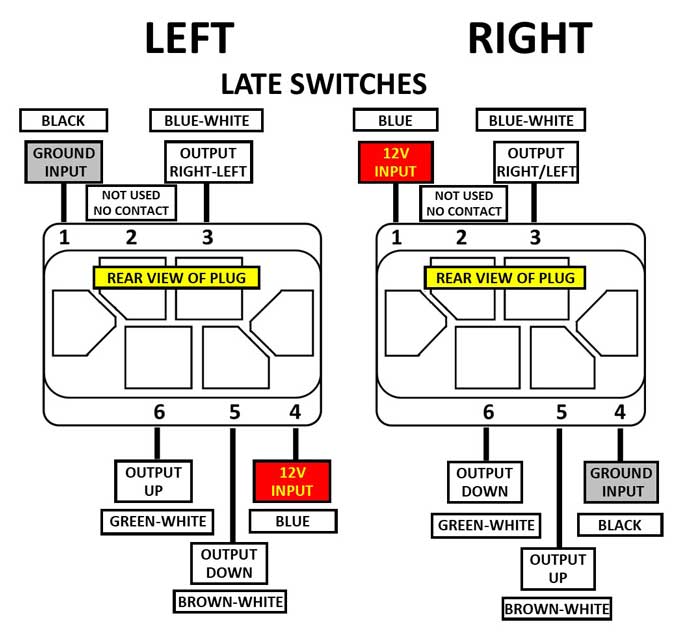
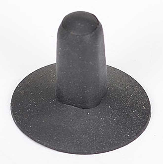
HERE ARE MY PHOTOS Yes, these photos appear a bit out of order. I have already removed these parts, but showing you the parts removed first will make it easier to see what you need to see. As you saw in the above video, the mirror glass back panel snaps onto the Drive Motor Unit. Those four LOCATING PINS (circled in RED below) insert into the four holes on the Drive Motor Unit. Those EIGHT plastic "L" CLIPS snap over the outer edge of the Drive Motor Unit. So those EIGHT CLIPS must be released. The best method to do this is similar to how the video describes, but I found those plastic clips to be very tight and it took a great deal of force to shove a small screwdriver under them and bend them open. You will undoubtedly be concerned about bending them so much that you might break some off. My advice is DON'T BE CONCERNED about that. Bend them so they are as free from holding onto the Drive Motor Unit as you can. If you break one or two, so what? Otherwise you may be tempted to just yank the mirror off in frustration. This Drive Motor Unit is way TOO FRAGILE for that. 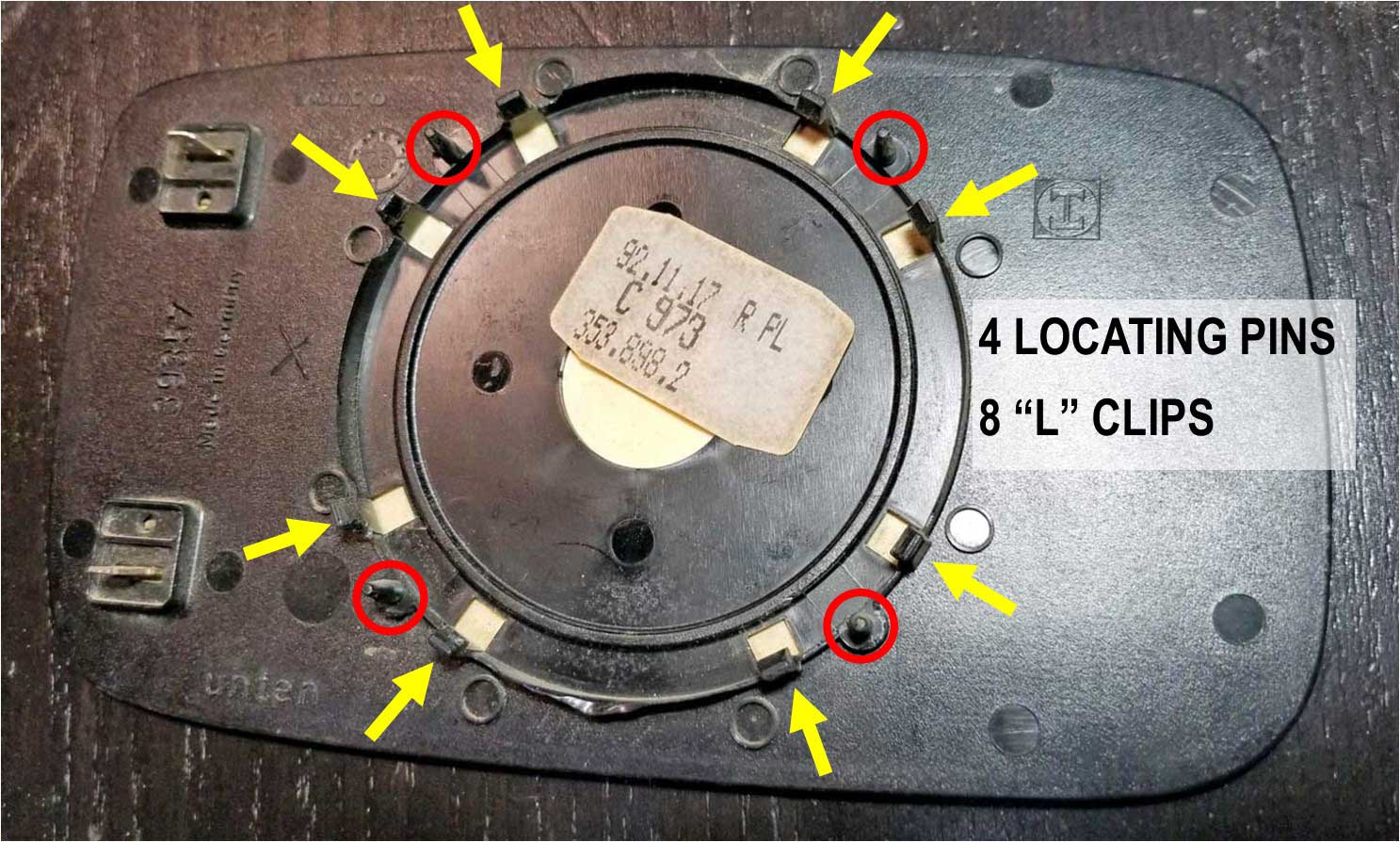 Click a photo to see a close-up.  While you look at the image of the LATE DRIVE MOTOR UNIT above, you can study how different it is from the MID Mirror Motor. This later unit above has TWO MOTORS; One motor for LEFT-RIGHT and one for UP-DOWN. The early type has only ONE MOTOR (and a solenoid). THIS LATE DRIVE UNIT IS FRAGILE! Here it is. Here's a close-up photo below of the carnage that's waiting for you if you try to yank the mirror off. That BROKEN PART can best be described as a rack (as in rack and pinion). That rack is moved by a gear on that motor, controlling the LEFT-RIGHT movement. This break destroyed the ability for the Drive Unit to control the LEFT to RIGHT adjustment. So hopefully you'll understand the importance of NOT pulling on this mirror glass. I'll return to showing you some photos below. 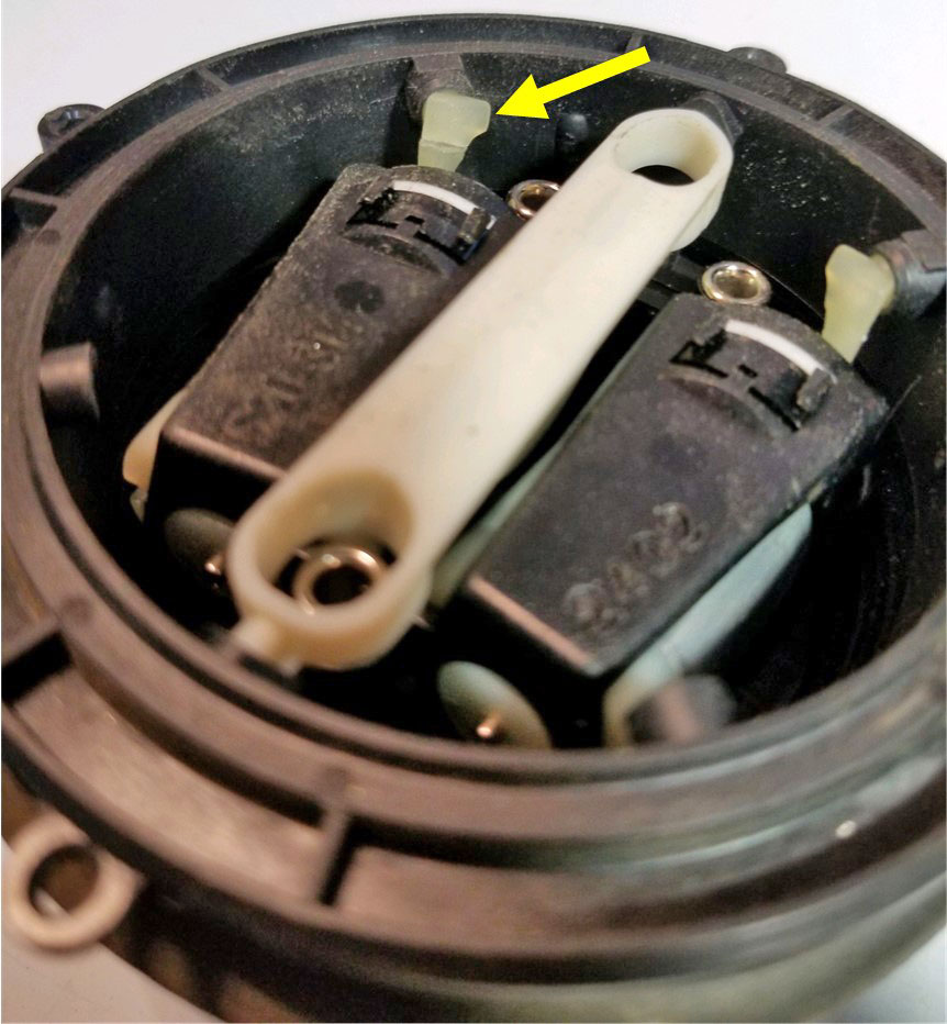 More images showing how the locating pins fit the Drive Unit and some close-ups showing those "L" clips. 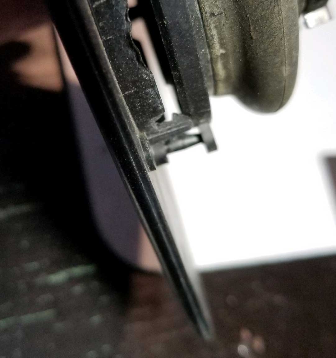 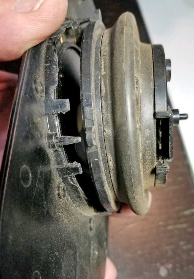 Once the mirror is free, you can flip it over and see the two heater connections below. Those simply pull off. 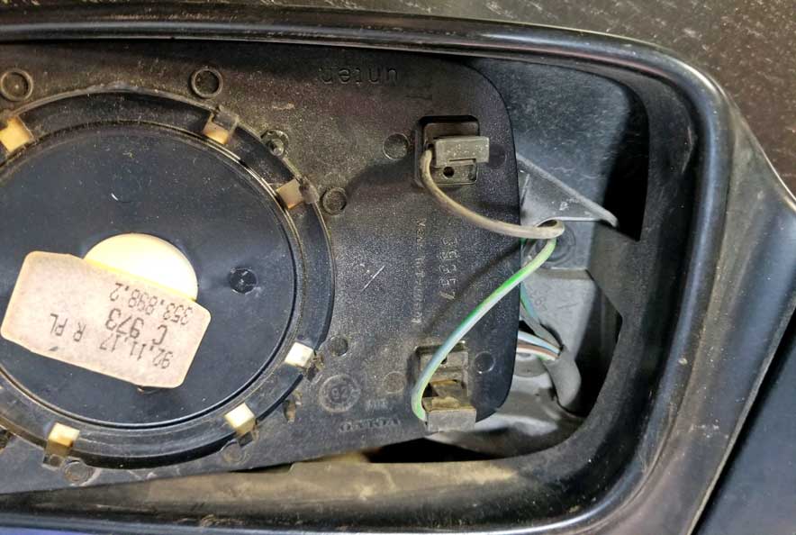 There are three screws holding the Drive Unit below. 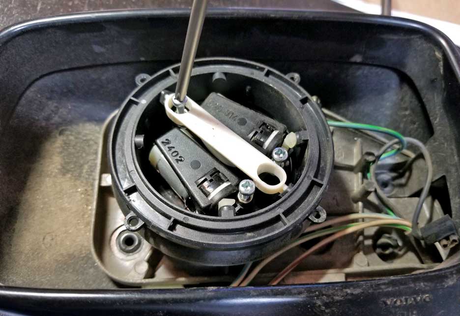 And there is a 3-pole connector on the reverse side of the Drive Unit below. There are two plastic hooks retaining it, so bending those a bit will allow the removal of this plug.  LATE MIRROR ELECTRICAL STUFF 1992-93 Here's some electrical information on this late mirror. You can refer to the diagram below and follow along. Each mirror has a Drive Motor Unit. Each Drive Unit has two drive motors. One motor moves the mirror LEFT-RIGHT and the other motor moves it UP-DOWN. For each pair of motors there are three wires. One wire goes to the LEFT-RIGHT motor, one goes to the UP-DOWN motor, and one wire goes to the other sides of BOTH motors. NOTE: If you study this closely, you'll see that the two mirror switches appear to be wired similarly to each other, however the POWER and GROUND inputs (Pins 1 and 4) are OPPOSITE on these switches. The LEFT switch gets power through Pin 4. The RIGHT switch gets power through Pin 1. LEFT-RIGHT ACTION: When the switch joystick is pushed LEFT or RIGHT, a power and ground signal is sent to a pair of wires to one of the Drive Motors. We'll call this one the LEFT-RIGHT MOTOR. This power and ground signal goes through Pins 3 and 5 of the switch. The internal design of the switch allows for the polarity of these signals to be swapped, which allows the motor to run in forward or reverse (for left and right), depending on the direction the joystick is pushed. UP-DOWN ACTION: When the joystick is pushed UP or DOWN, a power and ground signal is sent to the UP-DOWN MOTOR through Pins 5 and 6. Again, the internal design of the switch allows for the polarity of these signals to be swapped, which allows the motor to run in forward or reverse (for up or down), depending on the direction the joystick is pushed. NOTE: The internal design of the late switch will only allow for one motor in the Drive Unit to be energized at a time, so the mirror moves only in one direction at a time. MIRROR GLASS HEATER: Late 240 mirrors (1992-93) are designed to be heated for use in cold weather. A switch on the dash may be triggered, which activates a relay (Volvo PN 1324675). The relay sends power to heating elements inside the mirror glass.  A diagram for the relay connector pins is included in the diagram below. 240 LATE MIRROR WIRING DIAGRAM 1992-93 (A late mirror only uses a LATE switch)  If you're buying or assembling a late kit to install in a 240, these images below will help make sure you have it all. . . Click HERE to see testing information for LATE 240 mirror switches. |
So this section will try to straighten out errors or misconceptions and hopefully provide something useful and accurate.
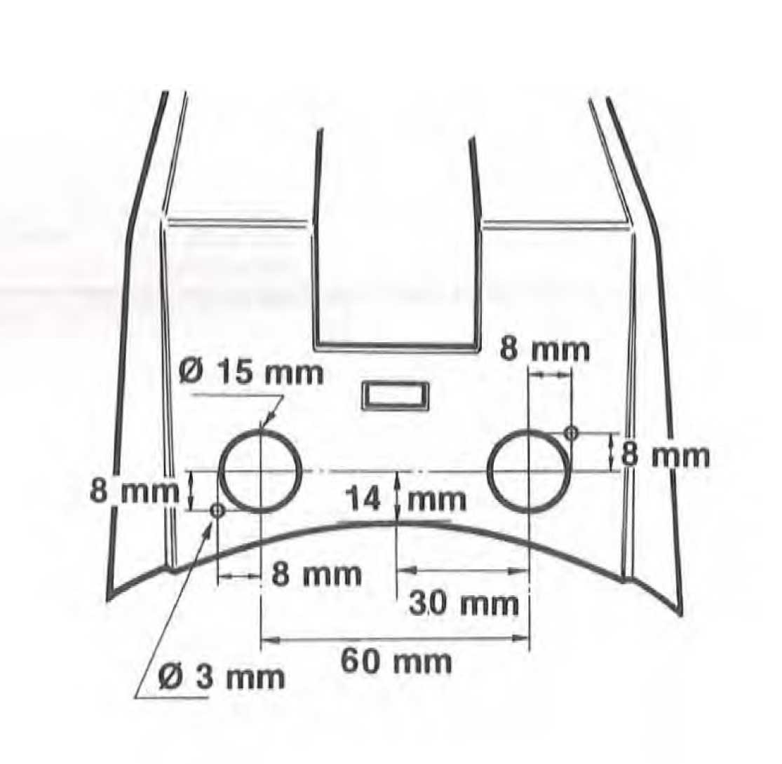
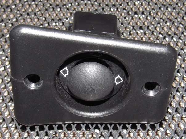
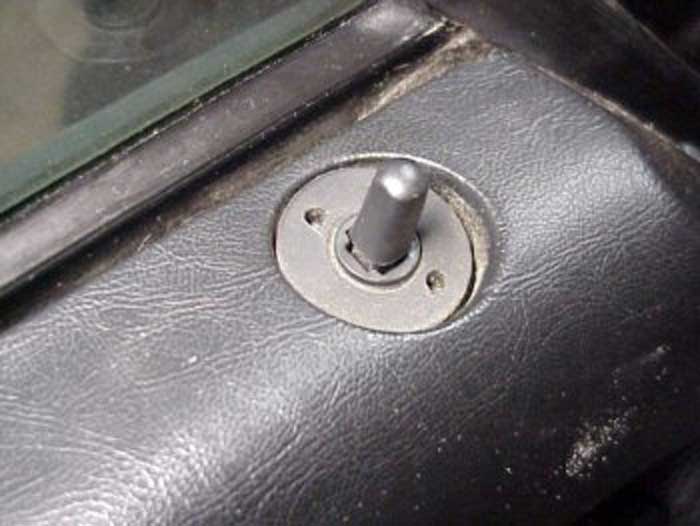
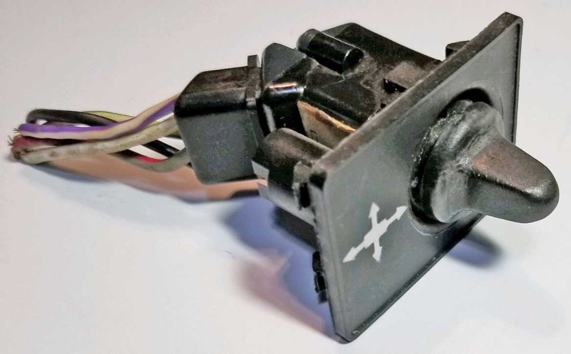
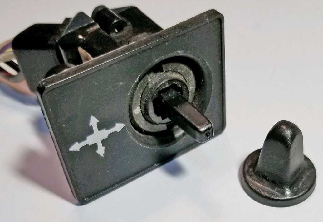
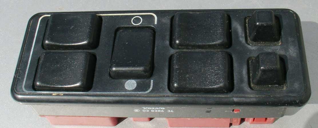
MOUNTING SWITCHES IN A CENTER CONSOLE The switches were normally mounted in the 240 center console either on the FRONT surface or TOP surface. 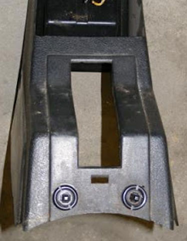  Those small holes next to the larger holes in the console play an important role. The small hole matches up to a locating pin on the switch to keep the switch pointed in the proper direction. The proper direction is shown below. The right and left switch is the same part, but they're mounted OPPOSING each other (180 degrees), with the connectors always facing outward.  
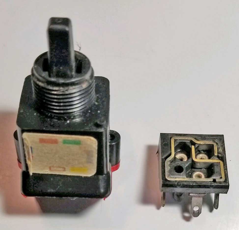
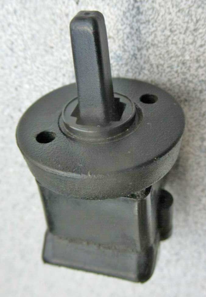
EARLY 240 SWITCH (For ALL early or mid mirrors up to 1991) This early mirror switch is identified in Volvo parts catalogs as PN 1235091. This switch has a dark gray colored bottom, although it will appear black in most photos. This switch has been NLA as a new part for a number of years. This switch is used for all 240/260 power mirrors from 1975 through 1991. 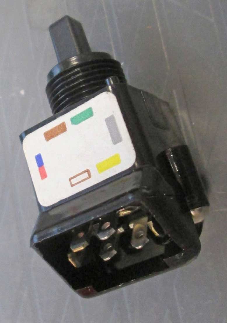 LATE 240 SWITCH (For all 1992-93 mirrors) This late switch is identified in Volvo parts catalogs as PN 3540358. It has a red colored bottom. It has also been NLA as a new part for a number of years. Parts catalogs show it's used in the 1992-93 240 only. This switch is externally almost identical to the early switch, except for a couple of differences. The first obvious difference is the red colored bottom. Also the connector pins are different. 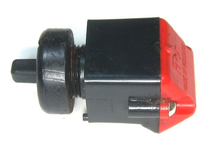 EARLY versus LATE SWITCH COMPARISON Other than the gray or red colored bottom, the first clue that these switches are different comes when you look at the contact pins. The early switch (up to 1991) has 6 contact pins and the connector plug uses 6 wires. The late switch (1992-93) only has 5 contact pins and the connector uses only 5 wires. The connector housing is the same for both switches, however the wiring order is not the same. Also you'll see internal photos further below showing these are very different internally too. 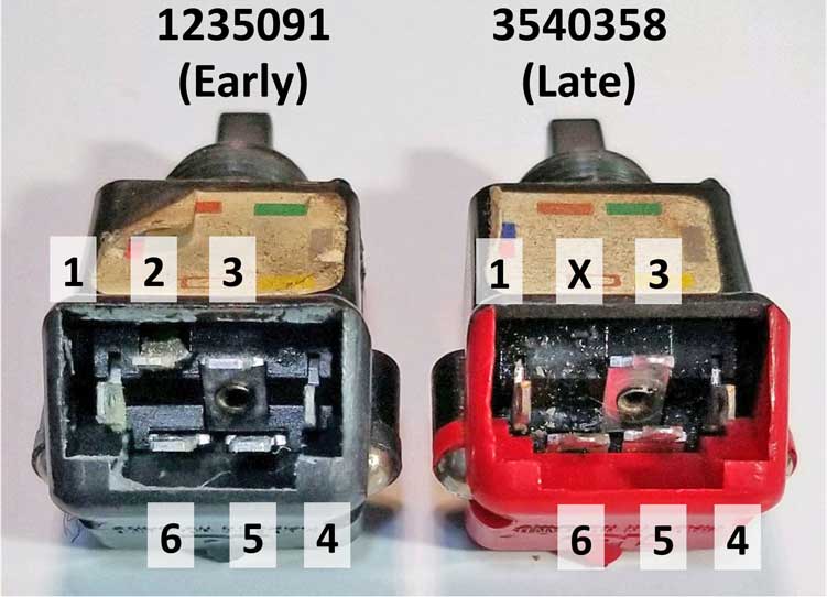
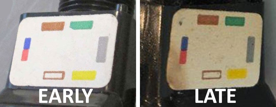 My opinion is these are NOT interchangeable. The wire color stickers shown above are identical on both switches, although the colors don't actually match actual wire colors used. There are some people who claim these switches are interchangeable, but after you see the info below, I think you'll disagree (like I do). If you can provide any input to the contrary, please email. While I have not explored the possibility of using an EARLY switch in some custom wiring configuration to power a LATE mirror, I think that still could be possible with some creative wiring. The opposite idea of using a LATE switch to power an EARLY 240 mirror seems impossible to me, considering the LATE switch doesn't have a way to send the power needed for the UP-DOWN solenoid. Maybe there's a tricky way using some wiring ideas I don't know about. I'm happy to have that discussion if you have any of those ideas. The INTERNAL circuits are quite different. 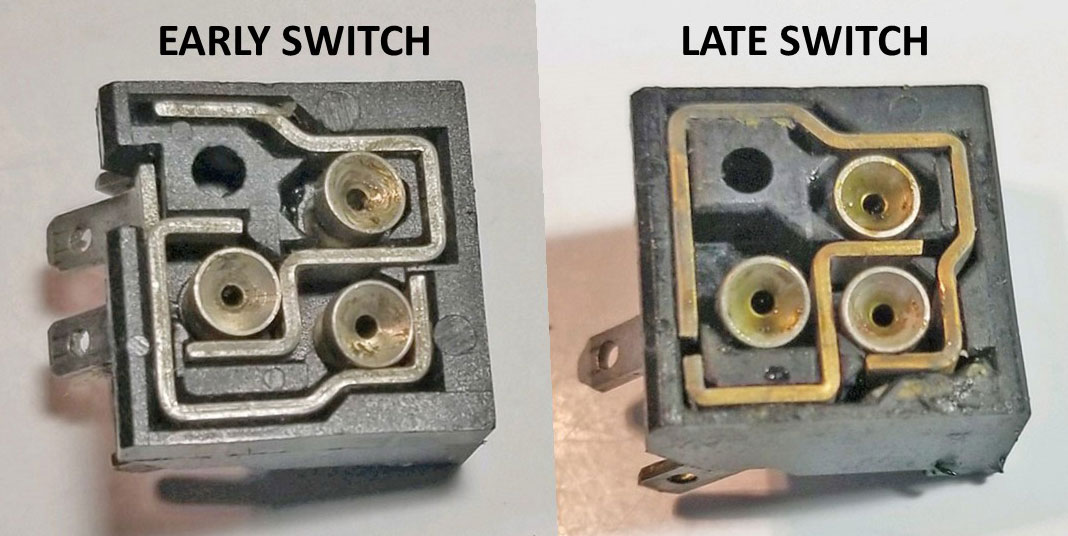 I have placed a side-by-side internal switch function diagram at the bottom of this section.
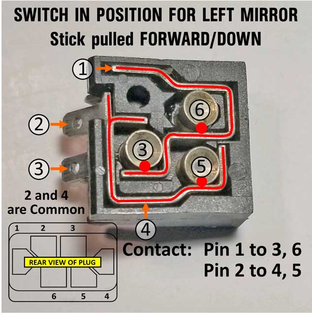
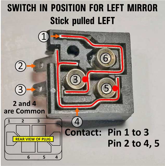
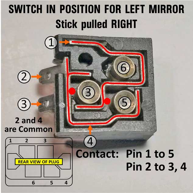
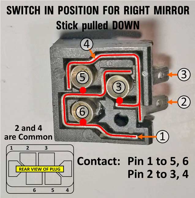
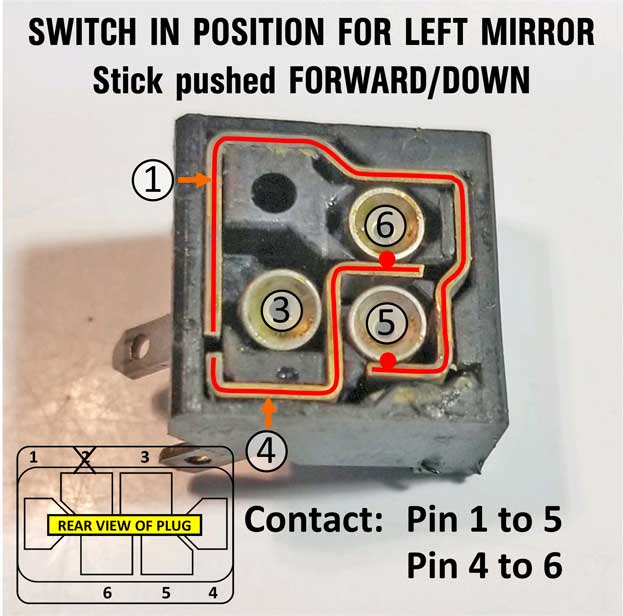
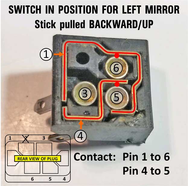
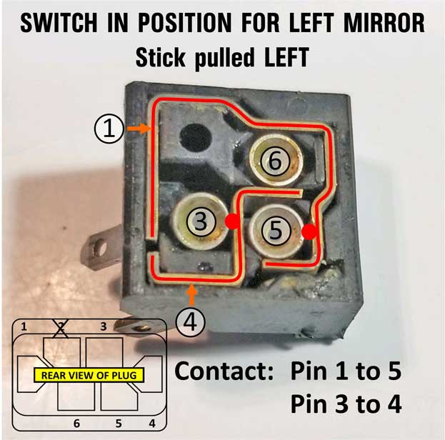
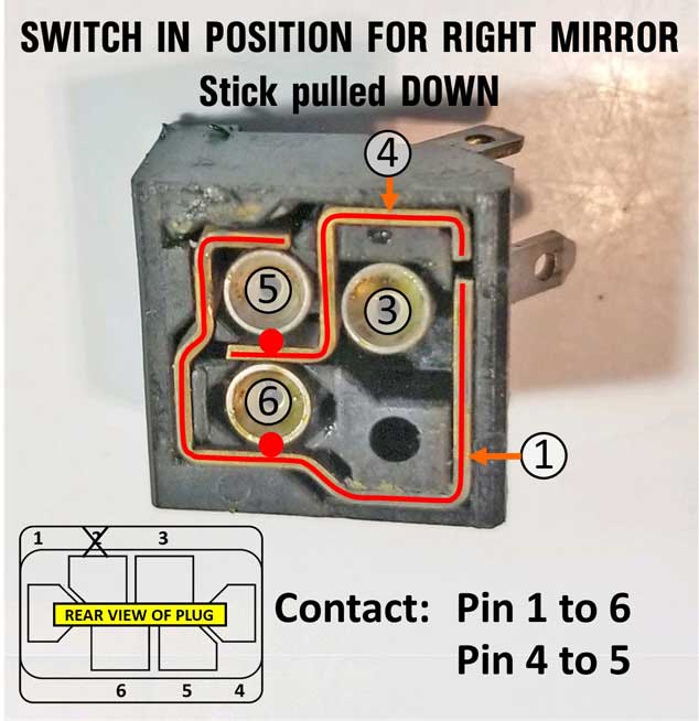
CONTINUITY TESTS First I tested EARLY 240 switch continuity. The below continuity tests were done to see what connects in the 6 pins at various toggle positions. If you test a switch and get different results, it might need some internal cleaning. Early 240 Switch Continuity (up to 1991)
This image below is a joystick position graph I made to show how this switch connects when positioned for a left mirror.  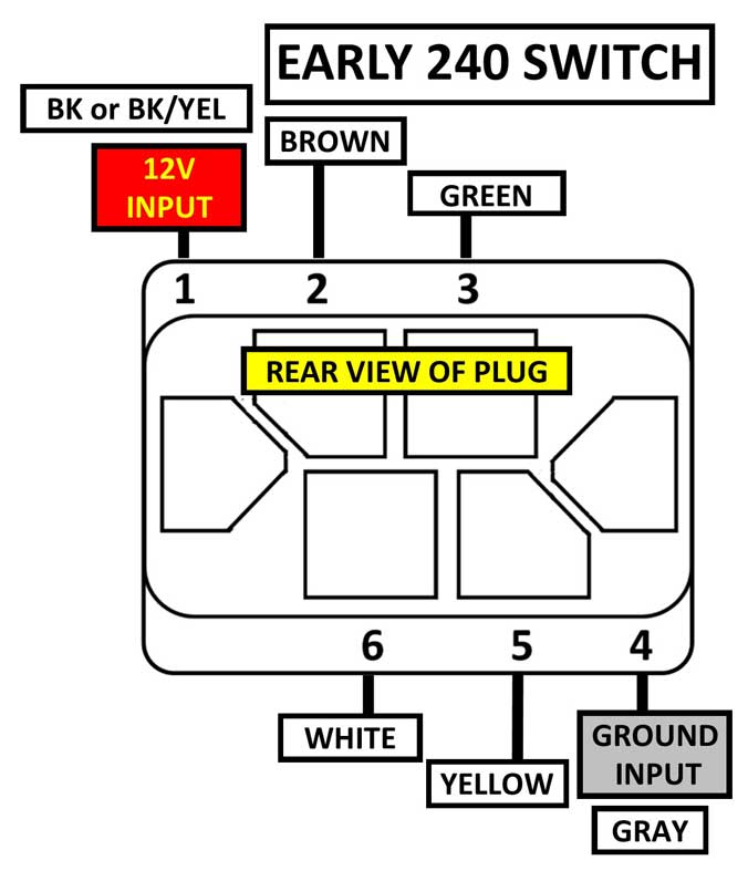 EARLY SWITCH FAULT TRACING The wire order will be the same for a left or right switch in a 240 up to 1991. Pin 1 will always be POWER input for both right and left side. Pin 4 will always be GROUND input (pins 2 and 4 are always common internally). You can use this table below to test for power and ground supply of pins 3, 5 and 6 at the switch or from the switch to the mirror. Wire colors below are those found at the switch connector for a 240 up to 1991. Early mirror wiring diagram can be found HERE.
Late 240 Switch Continuity (1992-93)
This image below is a joystick position graph I made to show how this switch connects when positioned for a left mirror.  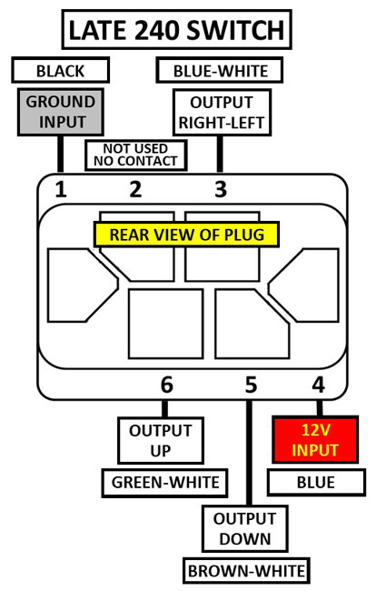 LATE SWITCH FAULT TRACING The wire order in the connectors will be different between the LEFT and RIGHT switch in a LATE 240. You can use this table below to test for power and ground supply of pins 3, 5 and 6 at each switch. Wire colors below are those found in a switch connector for a 1992-93 240. Late mirror wiring diagram can be found HERE.
EARLY vs. LATE 240 SWITCH FUNCTION COMPARISON Here's a side-by-side comparison of the internal functions of these two switches. If you're of the opinion that these switches are interchangeable or somehow compatible for some sort of retrofit, please contact me and help me understand. I just don't see it happening.  If those diagrams above are hard to understand, here's more. Each early mirror uses one motor and one solenoid. The solenoid allows that one motor to mechanically switch from Right-Left to Up-Down. Each late mirror has two motors instead. One motor controls Right-Left and one motor controls Up-Down. Most mirrors made in the last 30 years use this design. 
|
|||||||||||||||||||||||||||||||||||||||||||||||||||||||||||||||||||||||||||||||||||||||||||||||||||||||||||||||||||||||||||||||||||||||||||||||||||||||||||||||||||||||||||||||||
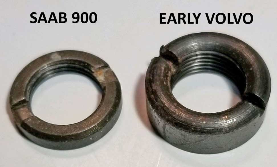
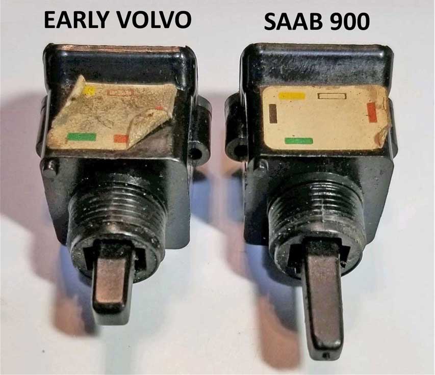
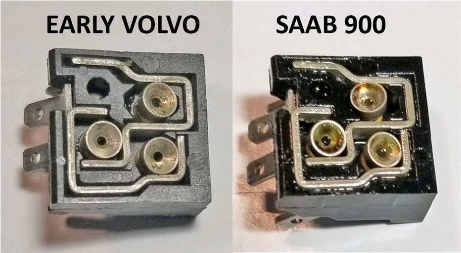
There is absolutely NO DIFFERENCE between a Porsche or Saab switch, except possibly for the decal. YES! Porsche and Saab are the SAME SWITCH. Can they be used in a VOLVO? YES. More detail HERE.  
SAAB 900 POWER MIRROR DIAGRAM The below Saab 900 diagram uses the same switch circuits as the Early and Mid 240 power mirrors. The Saab mirrors are constructed with a Drive Motor Unit that works exactly the same as the Early or Mid Volvo up to 1991. When you compare the two wiring diagrams you'll see that they're identical, except for one ground wire on each switch. This switch in a Saab does not use Pin 2 (which is a source to ground). Instead the BLACK ground wire to the SOLENOID in a Saab is grounded to the car chassis directly. 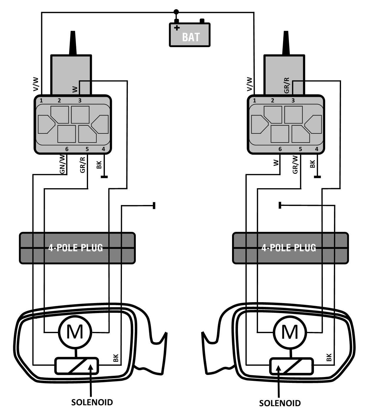 PORSCHE POWER MIRROR DIAGRAM The below Porsche wiring diagram uses the same switch circuits as the Volvo Early or Mid 240 power mirrors (up to 1991). These Porsche mirrors are constructed with a Drive Motor Unit with ONE MOTOR and a SOLENOID, which works exactly the same as the Volvo Early-Mid Volvo and also Saab. When you compare the diagrams with Volvo or Saab, you'll see that they're identical in operation, except that some Porsches used only ONE switch to control both mirrors using a LEFT-RIGHT SELECTOR SWITCH (approximately 1978-86). Image below shows a mirror switch in a 1980 Porsche 928.   SWITCH ORIENTATION If you're curious as to the orientation of this switch when it's mounted, it points the same direction as a Volvo EARLY or MID 240 LEFT SWITCH relative to its UP-DOWN and RIGHT-LEFT movements. 
|
Can a different style switch be used with 240 mirrors? YES! If you have a place to put them.
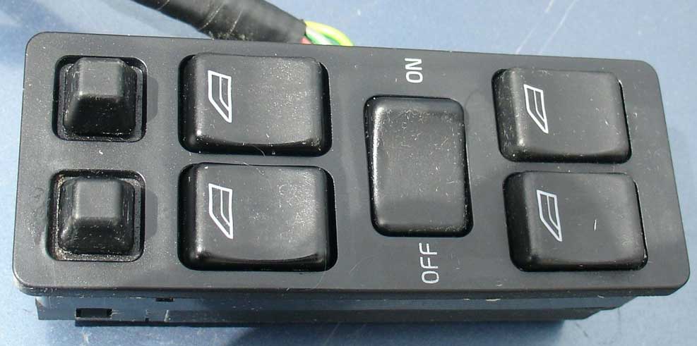
Volvo 700, 900 and 850 Mirror Switches For those of you who want something different, I think it might be an interesting modification to move some 240 mirror switches to a better location. So how about putting them on the door, like they do on 700/900/850 models?
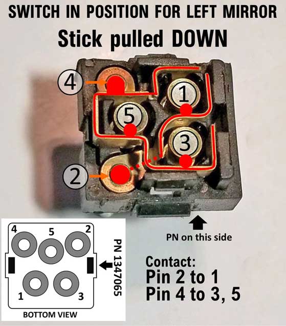
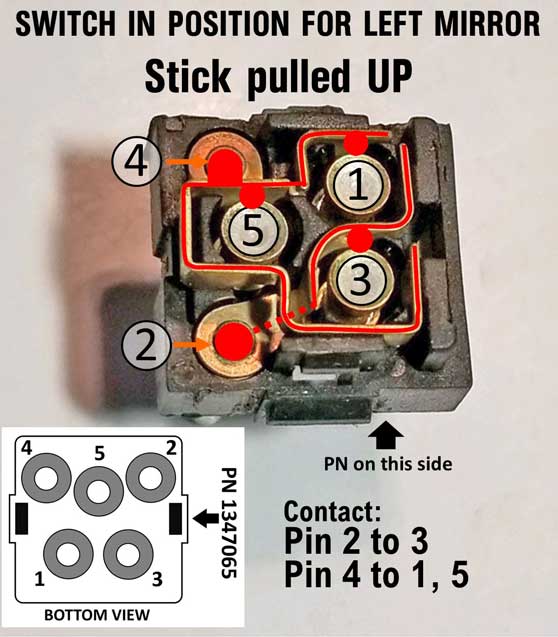
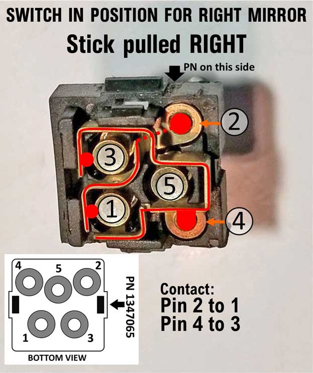
ELECTRICAL STUFF for EARLY 700 mirror switches. PN 1347065: from Volvo 740, 760, 780 through 1991. This switch will work for all 240 EARLY or MID power mirrors (used in 240 models up to 1991). This diagram below shows the internal switch functions of the EARLY 700 switch. It's almost exactly the same as an EARLY 240 switch, except for changes in pin numbers. Power input goes through Pin 4, Ground input is through Pin 2. Outputs from the switch to the mirror are Pins 1, 3 and 5. 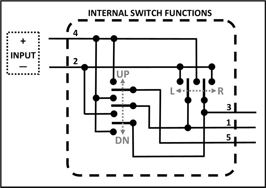 EARLY 700 SWITCH MOUNTING POSITION AND INTERNAL CIRCUITS PN 1347065 It matters which direction this switch is pointing when mounted. The below images show a proper mounting position for a LEFT switch. When this switch is mounted in the switch panel, the part number will be visible to the rear for both left or right. 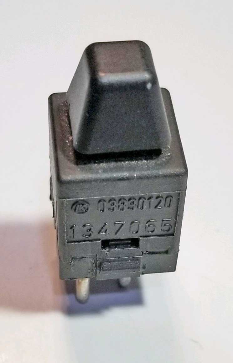 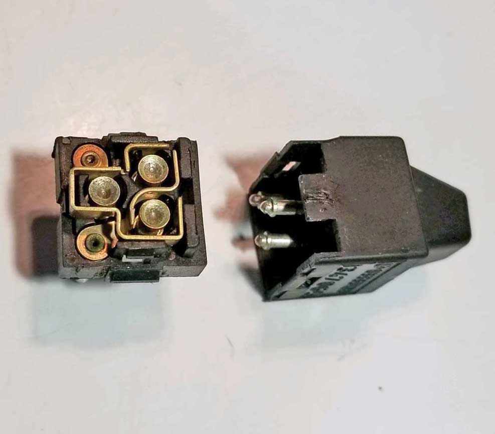 EARLY 700 SWITCH INTERNAL CIRCUITS PN 1347065 The below images show the internal contacts inside an EARLY 700 switch. I mapped out the circuits below help you understand where each one goes through the switch. These images show a switch in the proper mounting position for a LEFT mirror.
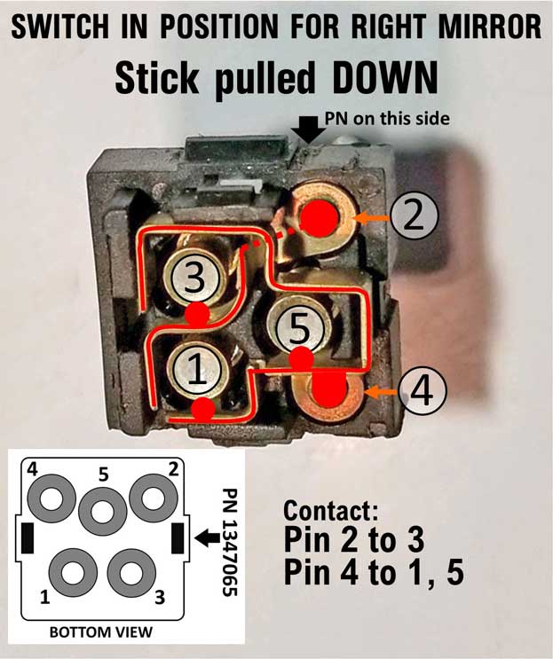
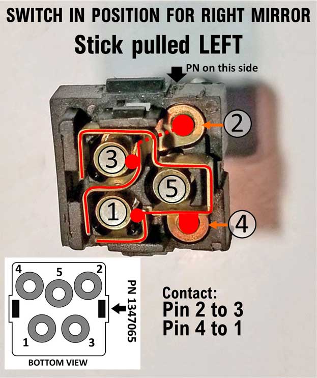
If using these EARLY 700 switches to control EARLY 240 (up to 1985) or MID 240 (up to 1991) power mirrors, here is the wiring information you'll need to know. This image below is an early 700 door switch panel. The mirror switches for a 700 are as shown below from the factory. Both are pointing the same direction. If you have read about 240 mirror switches above, you'll know that the LEFT and RIGHT switches are mounted opposing each other. These 700 switches are not originally mounted that way. 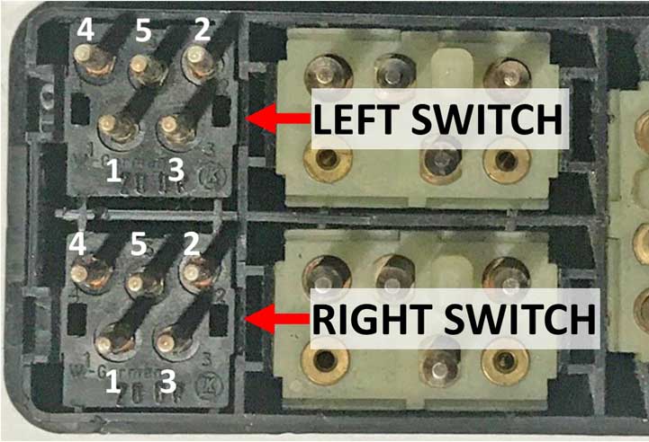 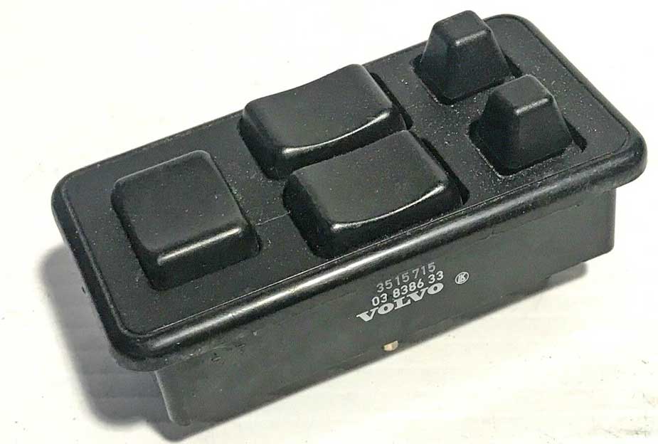 So there are two ways to make this work for EARLY or MID 240 mirrors. 1. Reverse the polarity of the RIGHT switch. This means you would make Pin 2 the Ground input and Pin 4 the Power input for the RIGHT switch. 2. Or you can keep the wiring the same and rotate the RIGHT switch 180 degrees. These switches are made to insert in ONE DIRECTION in a 740 panel. There's a notch in the switch that fits a peg inside the well. When turning this switch around, it'll go in most of the way, but the peg will interfere. So if you plan to rotate a switch, a remedy is to cut out that peg. A sharp Exacto knife works well to shave it down. 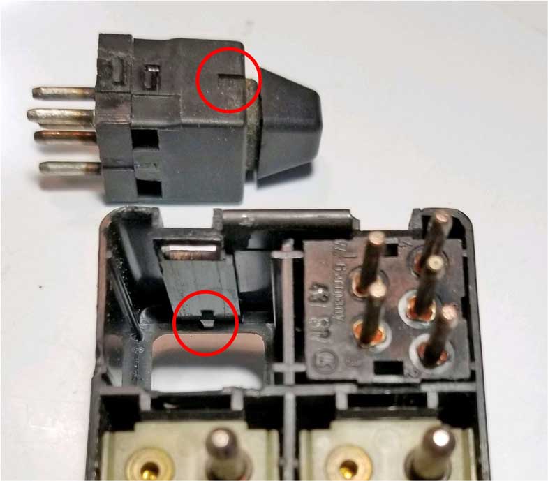 Once the RIGHT switch is turned 180º, you can use the below diagram to see what wires originally intended for the EARLY 240 switches can now go to these early 700 switches. 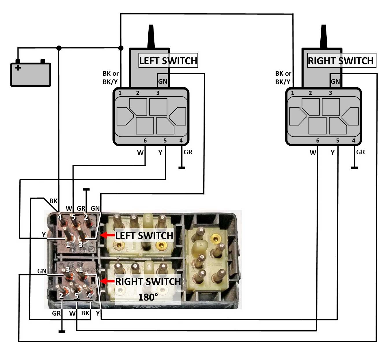 Here are the internal circuits below for the LEFT and RIGHT EARLY switches when done this way. Early 700 Switches PN 1347065 used for Early 240 Mirrors (up to 1985) or Mid 240 Mirrors (up to 1991).
|
|||||||||||||||||||||||||||||||||||||||||||||||||||||||
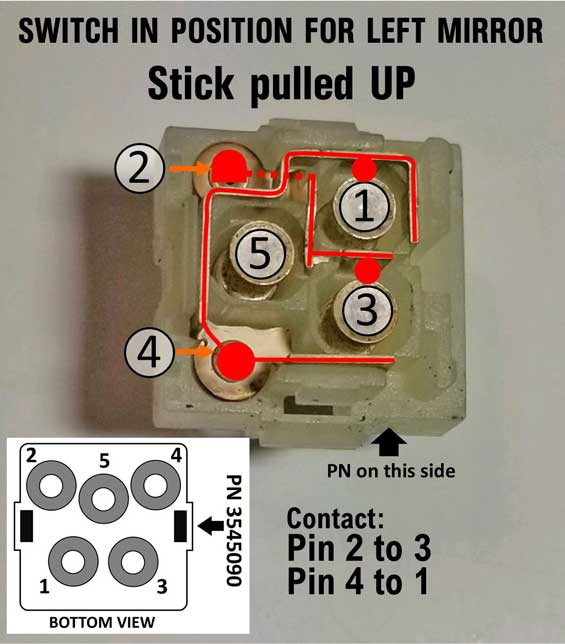
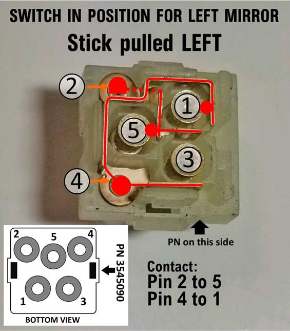
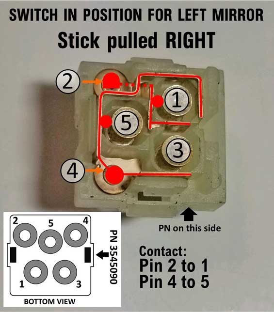
| LATE 700, 900, 850 SWITCH ELECTRICAL STUFF Here's some electrical information for the LATE mirror switches. PN 3545090: Volvo 740, 760, 780, 850, 940, 960 from 1992 and later. This switch will work for all 240 LATE power mirrors (those used in 240 for 1992-93). This diagram below shows the internal switch functions of the LATE 700 switch. It's function is similar to a LATE 240 switch, except for changes in pin numbers. Factory diagrams for late 240 switches show that the input terminals swap polarity between the left and right switch. For these switches below, the factory diagram shows the polarity to be the same left versus right. So power input should always be at Pin 2 and ground input should always be at Pin 4. Outputs to the mirror motors will then be Pins 1, 3 and 5. There is no need to turn one of these switches 180 degrees. Both should face the same direction. 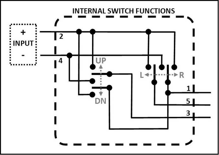 LATE 700/900/850 SWITCH MOUNTING POSITION AND INTERNAL CIRCUITS PN 3545090 When these switch are mounted in the switch panel, the part number will be pointing to the rear of the car. 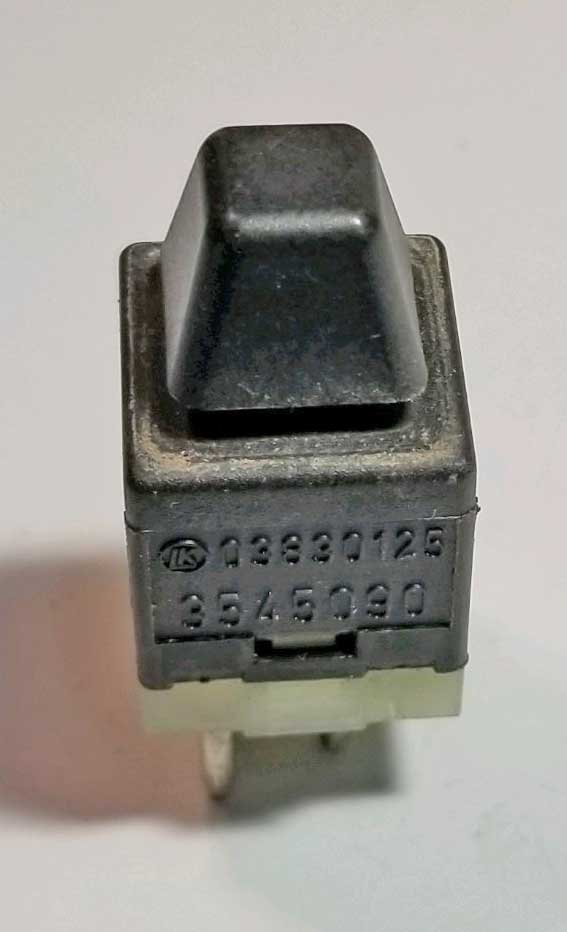 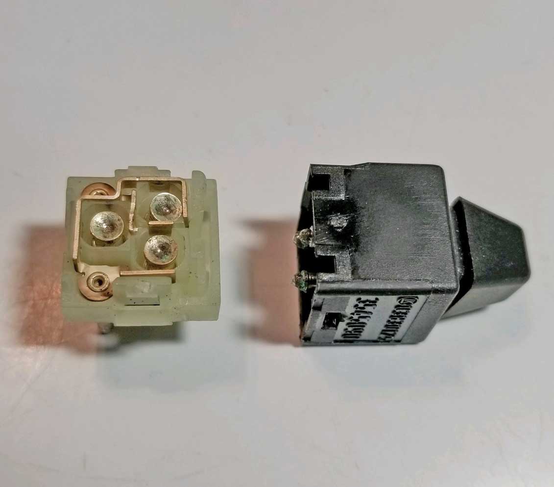
LATE 700/900/850 SWITCH INTERNAL CIRCUITS PN 3545090 I mapped out the circuits below to help you understand where each one goes through the switch.
I modified it to help make it more clear which pins connect.  LATE 700/900/850 SWITCHES Diagram for use with Late 240 Mirrors (1992-93). Switches should both face the same direction when mounted.  Your feedback is welcome: CONTACT |
||||||||||||
The use of this switch to power LATE 240 power mirrors (1992-93) was outlined in the following TB post: turbobricks.com/240-mirrors-switch-s70.378317. This info below will expand on this modification.   This switch is found in the driver door panel. It should be noted that this switch cannot be used for EARLY or MID 240 mirrors (any mirror prior to 1992).  |
|
|
||||
| davebarton.com |
prancingmoose.com |
240turbo.com |
Special Emblems |
|
| Prancing
Moose Stickers |
Volvo
Stickers |
Body/Chassis/Engine
Labels |
240 MODS and FIXES Page | |
| Other Car Brand
Stickers |
Steering
Wheel Labels |
Center Cap Labels/Overlays |
Cool Volvo
Products |
|
| Grill Labels/Overlays |
Volvo Wire
Harnesses |
Conversion Harnesses |
Harness
Parts/Connectors |
|
| Volvo Relays |
Coil Repair
Harnesses |
240 Window
Scrapers |
740/940
Window Scrapers |
|
| Adjustable Voltage
Regulators |
Horn Buttons |
240 Odometer
Repair |
740 Odometer
Repair |
|
| Volvo Gauge
Faces |
740
Turbo/Boost Faces |
240 Black Door Vinyl |
850 Odometer
Repair |
|
| ALTERNATOR Page |
240 Power Mirrors - Switches |
240 Oil Cooler Page |
240 Fuse Panel Page |
|
| Group A
Racing 242 Turbo Page |
240 Hydraulic Clutch | Fuel Pump RELAY Page |
240 Headlight RELAY Page |
|
| Used Parts & Extra Stuff for sale |
CRIMPING Page |
240 Ignition Page |
240 Headlight Page |
|
| 240 Gauge Electrical Diagrams | 240 REAR END Page | Yoshifab Catch Can Install | 240 TAILLIGHT Page | |
| Side Marker
Lights Page |
Gentex Mirror Upgrade | Yoshifab Drain Tube Install | Modified 240 Favorites | |
| SoCal Salvage Yards | Unleaded Racing Fuel | B26FT Stroker | Dave's 245 Spec Page | |
| 240 SUSPENSION Page | 240 Lowering Page |
240 Windshield Page |
240 WIPER Page | |
| 240 BRAKES Page |
240 Dash Top Gauge Pod | Cadillac 4-Note Horn Install | 240 DYNAMAT Installation | |
| 4 Speed Fan
Controller |
Electric Cooling Fan
Page |
BRUSHLESS Cooling Fan Page |
Tropical Fan
Clutches |
|
| 240 AC Page | "KOMFORT BLINKER" Upgrade | T5 Trans Conversion Page | 240 Engine Mount Page | |
| 240 VIN Page | Stepper Idle Valve Page |
Vacuum Diagrams | 240 HOOD Page | |
| 240 Exhaust Page | 242 Power Vent Window Project |
EFI Volvo Pin Function Diagrams |
Favorite Links | |
| R-Sport
Apparel |
Prancing
Moose Apparel |
Volvo Meet Photo Albums | Texas Volvo Meets and Events | |
| Ordering Instructions | Policies | PAYMENTS Page |
Mojave Road Trail Map Page |
|
| Returns | Shipping | Shopping Cart Troubleshooting | Contact Us |
|

|


 alternators are known for poor voltage.")


