|
2 4 0 T U R B O . C O M D A V E ' S V O L V O P A G E
|
||||||||||||||||||||||||||||||||||||||||||||||||||
|
2 4 0 T U R B O . C O M D A V E ' S V O L V O P A G E
|
||||||||||||||||||||||||||||||||||||||||||||||||||
| If
you have any comments or if you can improve this
information, please feel free to email. CONTACT |
| Plastic (Polycarbonate) Headlight Lens Restoration We all know how plastic headlight lenses look after sitting in the sun too long. If you don't mind spending a little time with some sand paper and elbow grease, here is my opinion on the best method to fix this. First, I'm a fan of Project Farm's YouTube channel. He has a good comparison video of a bunch of headlight restoration kits. According to this, the best results came from the SYLVANIA kit. The WORST KIT was the one from Harbor Freight. https://www.youtube.com/watch?v=iDB5U4QUdD0 Project Farm: Finding the Best Headlight Restoration Kit The above video is a bit too brief in showing how this is done, so here's a much better video below from FCP about the Sylvania kit, which I think is the best. https://www.youtube.com/watch?v=AE50QSxOWGw FCP: How To Restore Your Headlight Lenses: Sylvania Restoration Kit
|
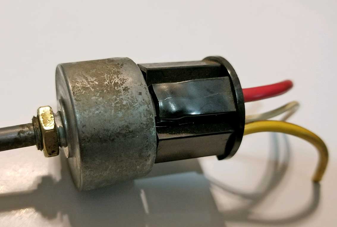
 The below diagram shows U.S.D.O.T. approved headlight connectors for 9004 bulbs.  1986 and Later 240 Headlight Switch This later switch has more pins than the early headlight switch. The input and output functions can be confusing. They are not what I would call straight forward and logical. 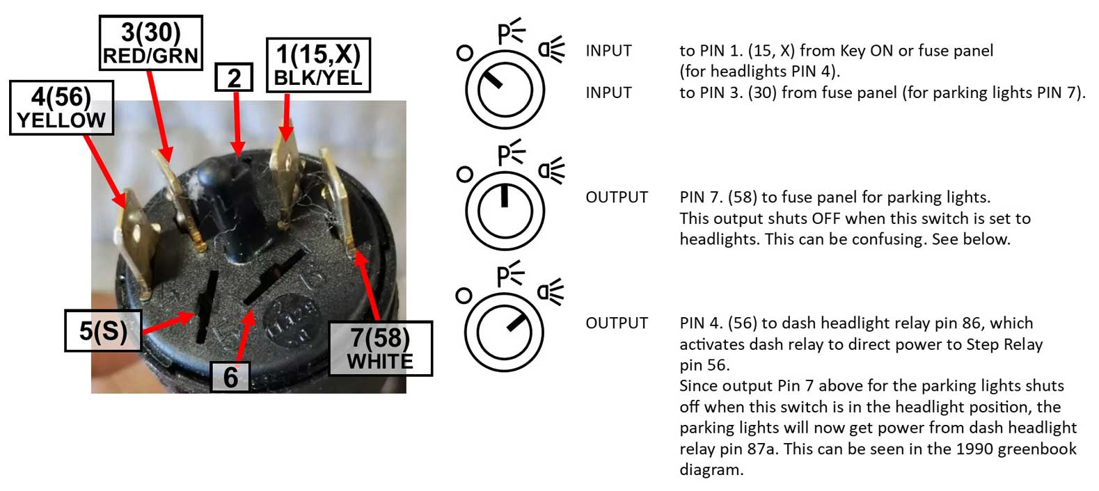 Image below showing 1990 taillight diagram, connection to HEADLIGHT RELAY. 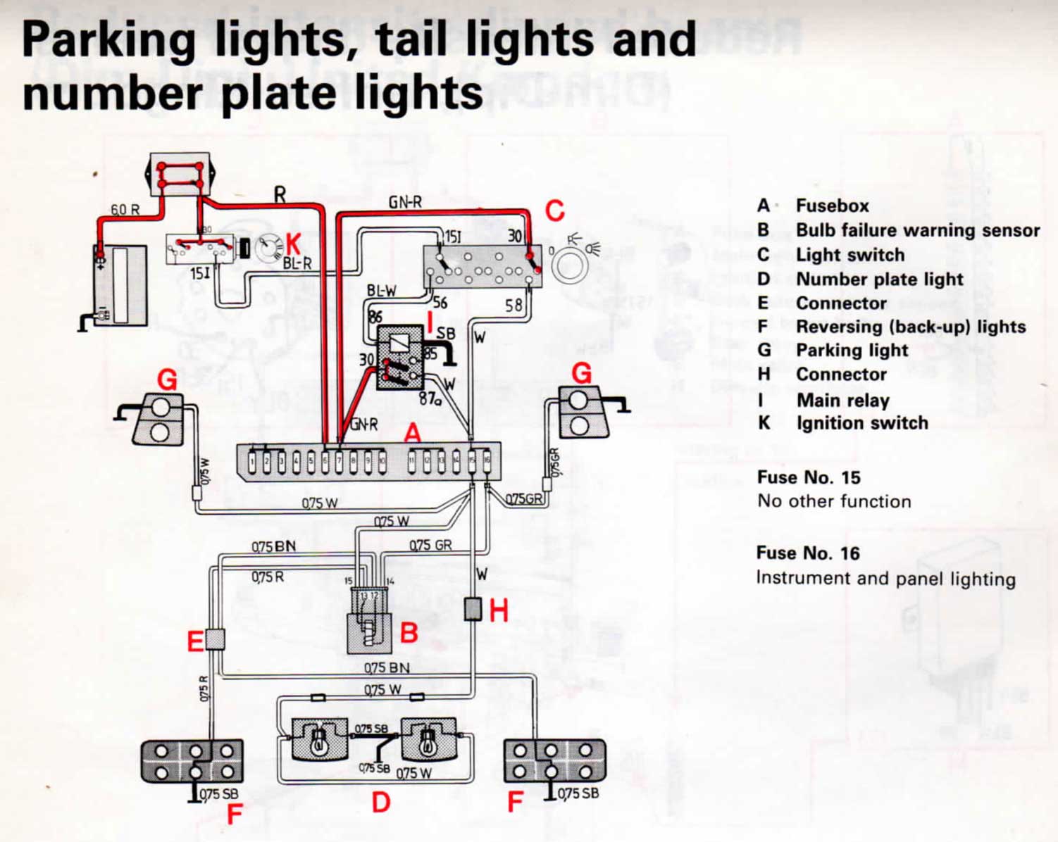 MORE ABOUT TAILLIGHTS in the TAILLIGHT PAGE. |
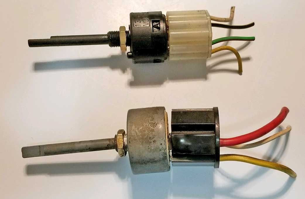
| 1975-85
240 Headlight Switches And Problems with Melting Plugs |
Originally I had assumed you could wire in a newer switch using the three wires in an older 240, This turns out to be wrong.
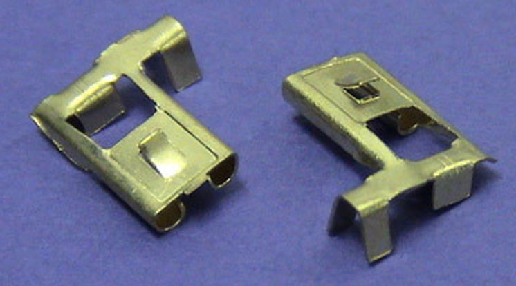
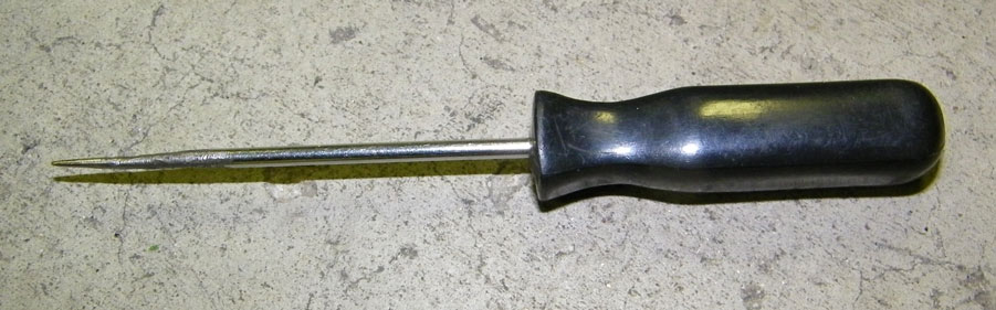
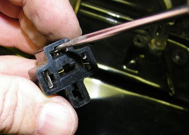
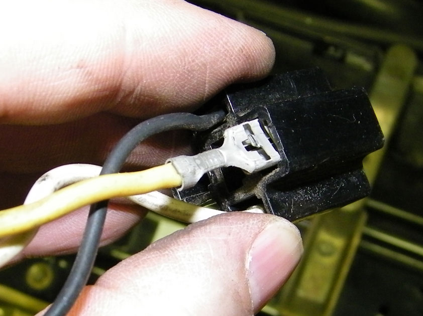
So I think this will be the solution to swap in a newer headlight switch and plug into an early 240. The added relay becomes necessary to allow the parking lights to come on with the headlights. Your input is appreciated. 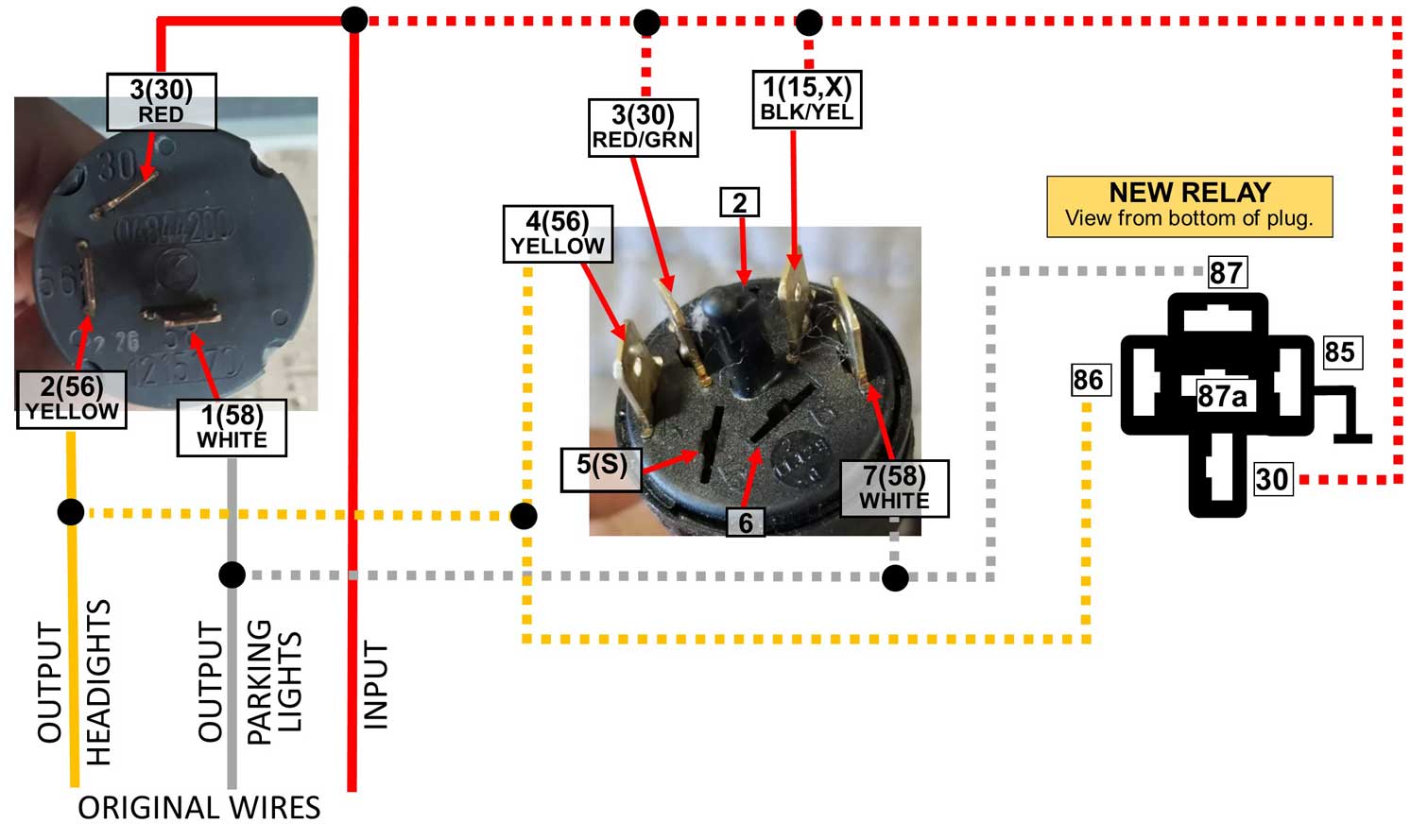 Click here for tips on removing wire terminal inserts from plugs like these.More information on adding a RELAY to upgrade your early 240 headlights can be found here: https://forums.turbobricks.com/showthread.php?t=250740 https://www.danielsternlighting.com/tech/relays/relays.html Early 240 Headlight Switch using 5 Poles (DRL in Canada)
In some markets (I believe Canada is one of these) the 240 was made so the wiring would activate the headlights whenever the car was running. This headlight switch is Volvo PN 1215169. I have not seen this wiring first hand, but I found the below images in Volvo Greenbook TP30808 Wiring for 1985 240 (pages 50-51).   |
|||||||||||||||
| Installing H4 Bulb Headlights instead of Stupid Sealed Beam |

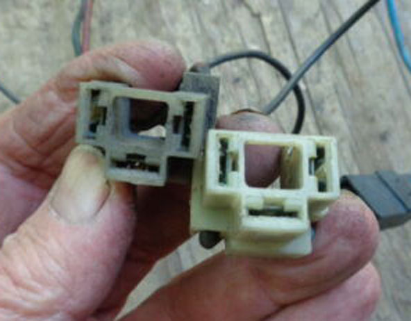 IMAGE BELOW: Here's the back-side of the headlights for a typical 240 with four rectangular headlights. You can compare this to the wire order in your headlight plugs. The High/Low headlight (outer lamp) will be the one with THREE wires. The High Beam has two wires.  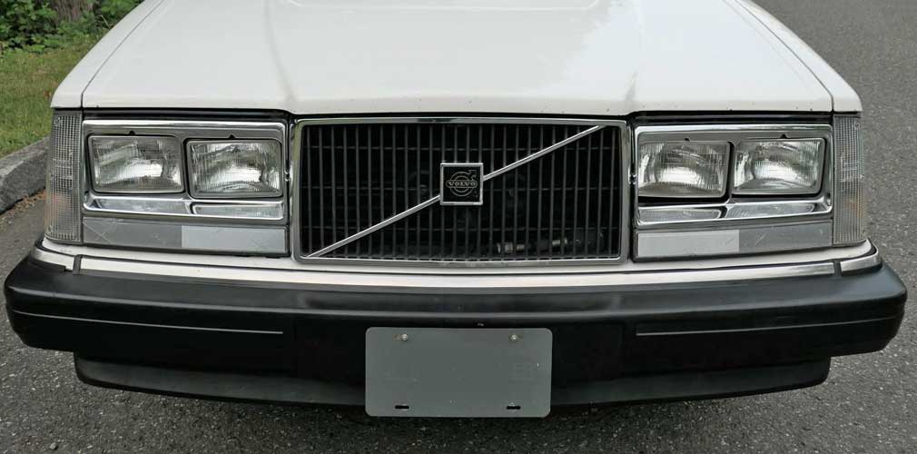 Changing to H1 and H4 Bulb Headlights If you carefully compare the plug wire order for the above sealed beam lights to the H4 plug order, you'll know they are NOT the same. So the terminals must be be moved to the below H4 configuration before using H4 bulbs. Go HERE for a terminal removal guide.  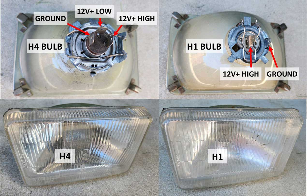 The ABOVE headlights are used for 240 "quad square" headlights, except of course these use superior H4 bulbs (for the outer high-low) and H1 bulbs (for inner high beams). They were made by Cibie and Hella with high-quality glass lenses and of course never actually came on Volvos in the U.S. from the factory. Here's video where a four headlight Volvo with sealed beam lamps was upgraded to H4 lamps. https://www.youtube.com/watch?v=QDdVYnyWgdc |
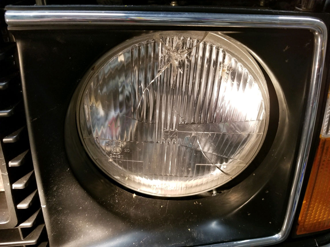
| E-Code Headlights |
| E-Code headlights get their name from this CODE with 'E' mark embossed in the lenses (below). All European approved headlights had this. It may say 'E2' like this one or it may have a different 'E' number. This E-mark was an approval mark regulated by the ECE (Economic Commission for Europe). The code shows it's approved for the countries where the European test agency granted approval. The E-mark certifies that the product met and complied with specific automotive requirements.  When our beloved 240s were imported to the U.S., the U.S. Department of Transportation (USDOT) had their own ideas of what good lighting should be. Their motto: If it was good enough 60 years ago, it must still be good. So all U.S. 240s got super crappy sealed beam headlights with inferior lighting.
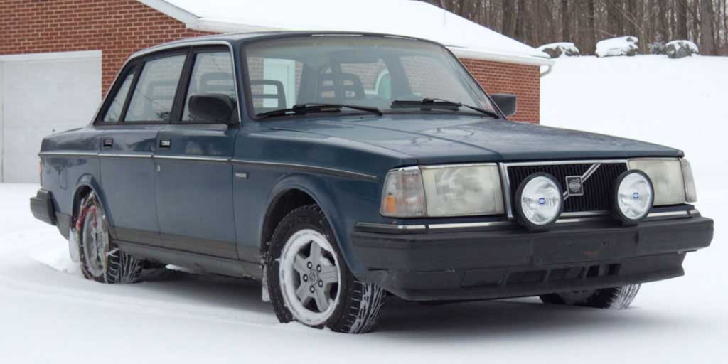
So originally, all 4 cylinder 2-door, 4-door and wagon model 240s got these headlights. Of course in Europe, these round headlights were the superior E-Code type using the H4 bulb. Not in the USA. This TWO headlight front was retained on all 2-door models (except for the 262C) through the 1980 model year, while other models changed a bit. 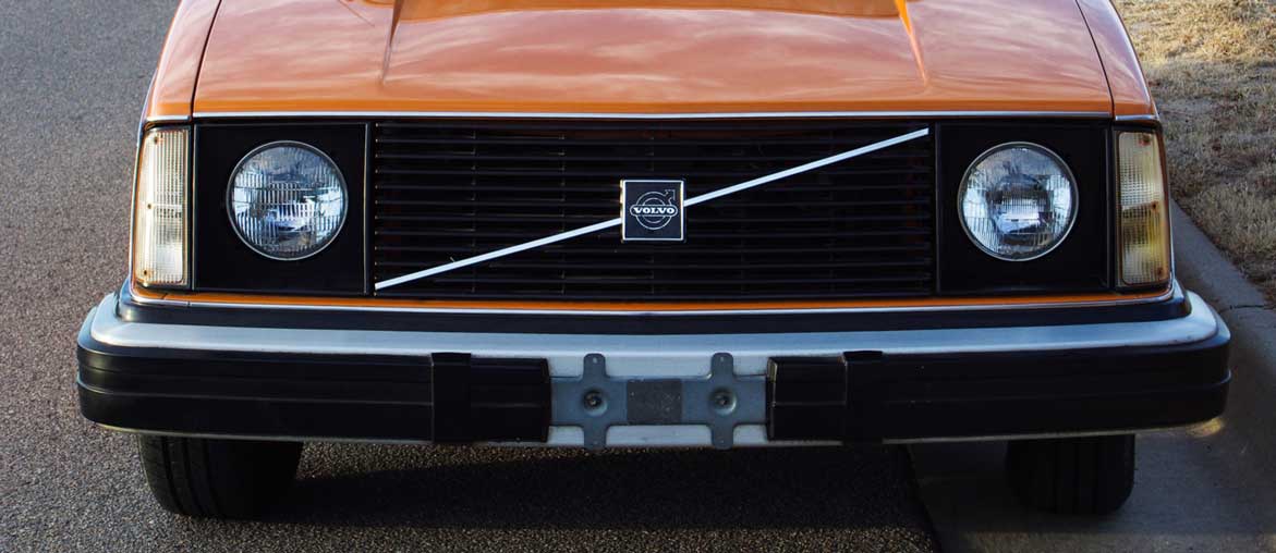 The FOUR ROUND headlights in this photo appeared on U.S. 6-cylinder models first (260 models). They would then later appear on U.S. 4-door and wagon 240 models up through 1980. These four round headlights are 5.75 inches (146 mm) in diameter. Again, for U.S models these were originally inferior U.S. DOT approved sealed beam lights, but of course they can be replaced by better E-code halogen headlights if desired. When the 4-cylinder 240s began using these four round lights, the up-scale U.S. 6-cylinder models (262, 262C, 264, 265) then began receiving four RECTANGULAR headlights. 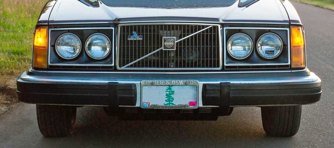 Europe was quite different. The European (E-code) large rectangular headlights (which use one H4 bulb per headlight) first appeared in 1975 on the 262C. Some of these cars received an extra special headlight version shown below with wipers. This style E-code headlight eventually became standard for most Euro version Volvos through the 1980 model year. U.S cars were never so fortunate to get these headlights. 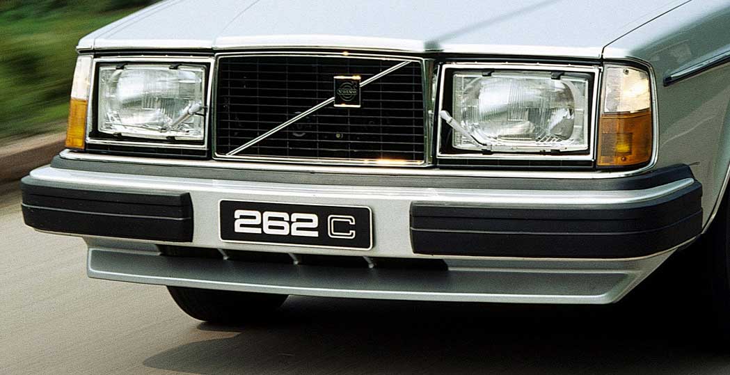 These are similar to the above 1980 or earlier E-code headlights shown above. This was a DUAL BULB version using two H1 bulbs per headlight, one bulb for low beam and one for high beam. This set is on a 1984 240 Turbo. 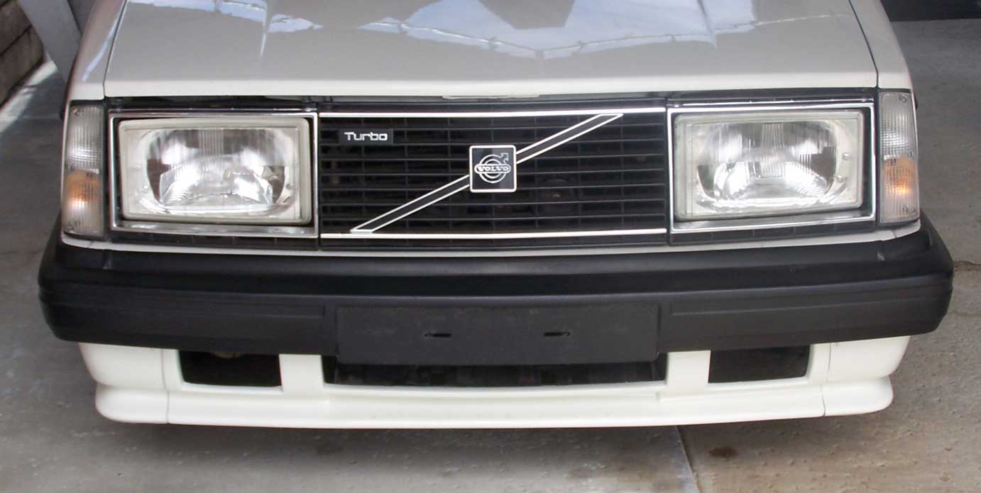 If you look closely at this photo below, you can see the second smaller curved reflector inside. This extra reflector is for the high beam and it will tell you this headlight uses dual H1 bulbs. Only this dual bulb style headlight will have this extra reflector.  These square headlights were optional in some E-code markets in 1979-80, such as the Netherlands and Australia (and maybe some other places). This headlight uses one H4 bulb per headlight. Never available in the USA. 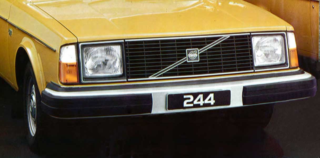 These four rectangular headlights below first appeared on 1977 U.S. up-scale models, such as the 262C and other 6 cylinder models. The headlights are 4 x 6 inches (102 x 152 mm). 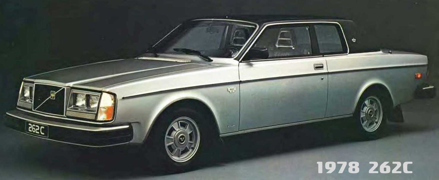 The four rectangular headlights later became standard on ALL U.S. 240 and 260 models from 1981-1985. Of course the USA versions used inferior U.S. DOT approved sealed beam units. Greatly superior E-code headlights in this size are available, which use one H4 (high-low) bulb for each outer headlight and one H1 (high beam) bulb for each inner headlight. These headlights are 4 x 6 inches (102 x 152 mm). This U.S.A. 1984 245 Turbo below originally came equipped with the same four rectangular headlights shown above. For 1985 or earlier U.S. 240 owners, these headlights below (sourced from a 1980 or earlier Euro 240) are a direct bolt-in and a welcome improvement for those who can import them from a country using E-code lights. These early H4 bulb versions pictured below are shown mounted on a U.S. 1984 245 Turbo. No changes were needed to the hood, grill or turn signals on this. These early headlights bolt right in.  This U.S. 1984 242 Turbo below also originally came with four rectangular headlights. These E-codes originally came from a 1980 or earlier European 240. The turn signal lenses were changed to Euro style dual color, but the turn signal assembly did not change. 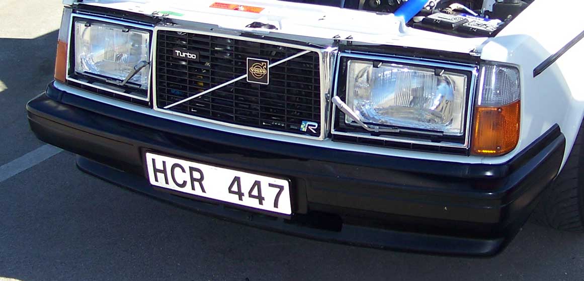 This is the same U.S. 1984 242 Turbo as above, except this later photo shows the change to a flat hood and grill. No sheet metal changes are needed, except of course the new hood.  In 1981 Volvo re-designed the front sheet metal for European 240/260 models. USA got left out in the cold and continued to get the old 4-headlight version seen above through 1985. These 1981 and later E-code versions below used one H4 bulb per headlight. The flat hood shown below was the same hood used on earlier flat hood 240s in Europe and USA. Some up-scale versions in Europe (6-cylinder cars) received a peaked hood and a different grill. The new sheet metal changes for 1981 and later European versions included the following: Different front fenders to accommodate the larger, re-designed turn signals. And a different sheet metal piece directly below the headlights and grill (shown here below). 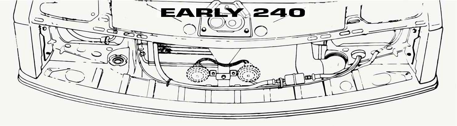 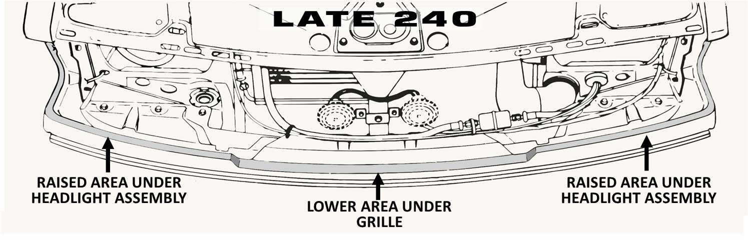 And you'll also notice that Europe abandoned the larger aluminum "commando" bumpers in 1981 (below car is a Euro 1981 240). The big bumpers stayed on U.S. cars through 1982 and on Canadian cars for a year or two longer than that. 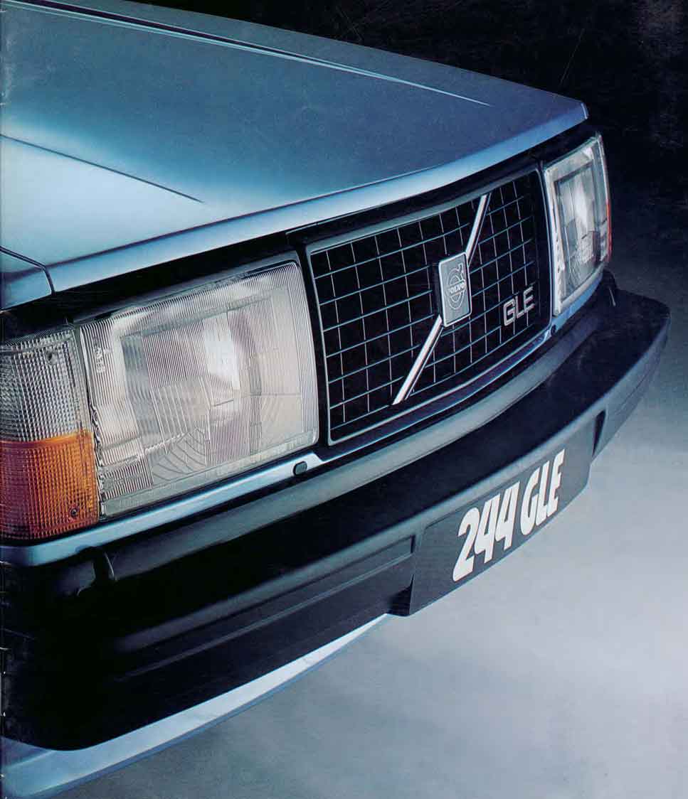 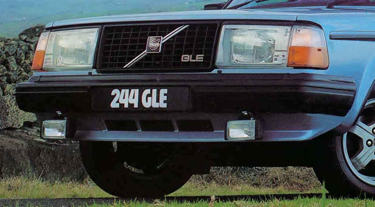 These E-code headlights above and below are the same, except for the chrome trim (instead of black trim). This model below is a U.S. 1986 or later model that has been fitted with E-codes sourced from a Euro 1981 or later 240. The U.S. 1986 has a raised/peaked hood and chromed grill surround. This is the more common style of Euro headlight/grill combo that will fit a U.S. 1986-93 240. Volvo continued using these headlights on all Euro 240s through 1993. If you can find a set of these E-codes for your U.S. car, they're a direct bolt-on to any U.S. 1986-93 240. Be sure to buy the Euro turn signals too, since the U.S. turn signals will not correctly fit next to the E-code headlights and the turn signal lenses will not interchange. 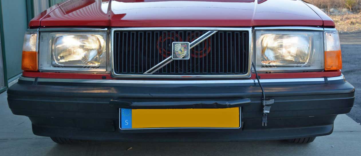 1986-93 240s imported to the USA received the same front SHEET METAL that Euro versions got for 1981-93. U.S. versions did not, however, receive E-code headlights. Instead the U.S. versions received inferior U.S. DOT approved headlights with plastic lenses. At least these weren't sealed beam units. These headlights use replaceable 9004 bulbs. The turn signals appear to be very much like the above Euro versions, however they are not interchangeable. If you buy E-code headlights for a 1986-93 240, buy the E-code turn signals to match. 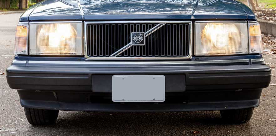 |
| LAMIN-X PROTECTION FILM |
| If
you have expensive or rare GLASS headlight lenses that you want to protect
from rock chips, breakage or pitting, spend the money to get some good, thick headlight protection film. If you search for Lamin-x or other universal headlight protection film, you'll mostly find a lot of pre-cut kits for many different newer cars. There are no pre-cut kits for older Volvos, so you need to buy universal uncut sheets or rolls.
 This universal Lamin-x film I used first turned out to measure only 8 mil thick (0.008 inch or 0.2 mm). Perhaps this thickness would be OK for paint protection, but it did not protect my headlight. I then found the below Lamin-x film, which is available in 40 mil thickness (0.040 inch or 1 mm). When I found this thicker stuff, it was only available in a bulk roll, 12 inch x 15 feet (or longer). The 15 foot roll was about $133. I bought a roll. Since I had lots of extra film left over, I sold it to friends for a small price per foot to cover the cost of the roll. https://lamin-x.com/12-x-15-roll-of-40-mil-clear.html More bulk rolls: https://lamin-x.com/rolls/lamin-x-rolls/ 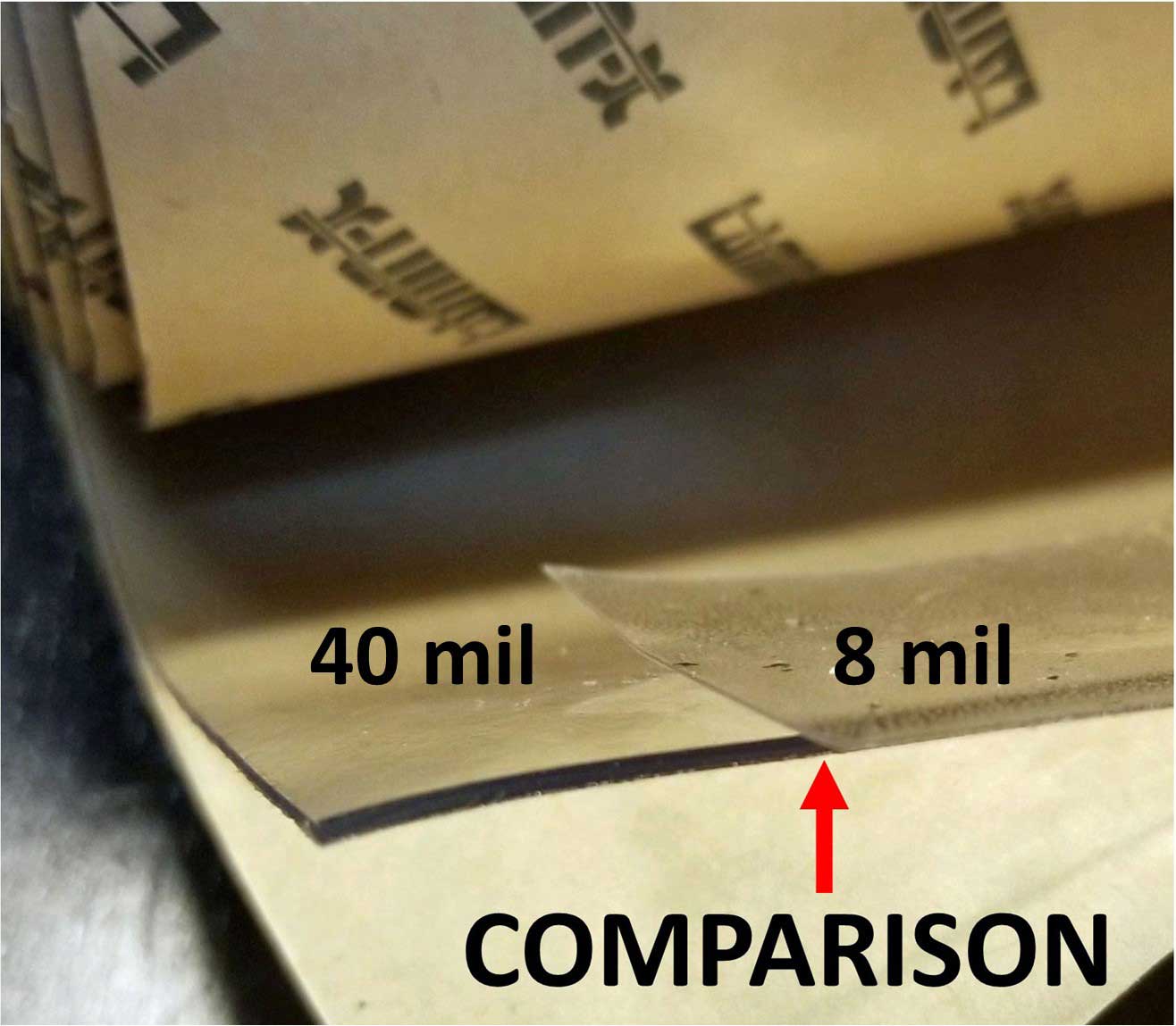

Here's a comparison photo above of thicker 40 mil versus thin 8 mil. 12 inches square can be used for two 7 inch round headlights, however you will probably really only need about 6 3/4 inch circles for that size.  |
|
| INSTALLATION OF LAMIN-X https://www.youtube.com/watch?v=hX_9ZhWzpHY LAMIN-X CHANNEL: https://www.youtube.com/channel/UCEksXxq7yPaVLNhYQScg30A |
| LED HEADLIGHT BULBS Are they finally good enough to replace Halogen? Yes, if you spend the money. |
For a long time I used 80/100 watt H4 HALOGEN bulbs, which were much brighter and far better than any stock headlights. So my lighting was very good. Good E-Code H4 headlights are well known for the great beam pattern and lots of brightness. I had no complaints. The only negative with high wattage halogen bulbs is that they use a lot of current. You should be using relays and heavy gauge wire for direct battery power when using high wattage halogens or you can very easily overload your switch or connections. So LED bulbs have an advantage here. They typically use about 30% to 50% less current than a high wattage H4. 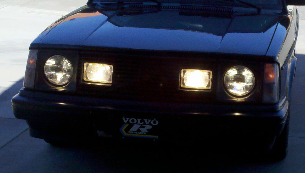 I have a NON-VOLVO car, which happens to be 2018 Subaru. It came with factory LED headlights. Those lights are EXCEPTIONAL, so I had been hoping eventually the aftermarket would catch up to that kind of quality, brightness and beam pattern. In 2020 I saw some videos from Headlight Revolution (I placed some of those below). This first short video is a simple brightness comparison between standard Halogen bulbs, upgraded 100 watt halogen bulbs and high-end LED bulbs. https://www.youtube.com/watch?v=qaM9YW_acqQ This and other videos below led me to reach out to Headlight Revolution to ask more about things like how good the LED H4 beam pattern looked in an E-code headlamp housing and how bright the latest high-end LED H4 replacement bulbs were. I was interested in how it would compare to my already pretty awesome hi-watt H4 (100 watt) halogen bulbs. They offered some pretty good responses, so I took a chance and I bought some LED H4 bulbs (below) to try out in my round E-codes. I tried the GTR Lighting Ultra 2.0 bulbs shown below. These are not like cheap bulbs that you'll find all over the internet. These were over $200 for the pair. The performance is definitely exceptional. More below. Direct link here for the H4 version shown below: https://www.headlightrevolution.com/H4-9003-Ultra-2.0_2 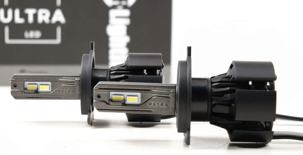
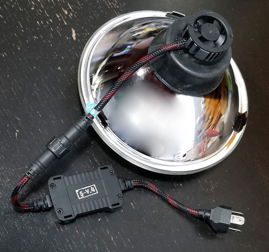
I also tried the S V.4 LED bulbs shown below and at the link below for the H4version. These are equally exceptional. These were also over $200 for the pair as well. More below. https://www.headlightrevolution.com/s-v-4-led-headlights-h4 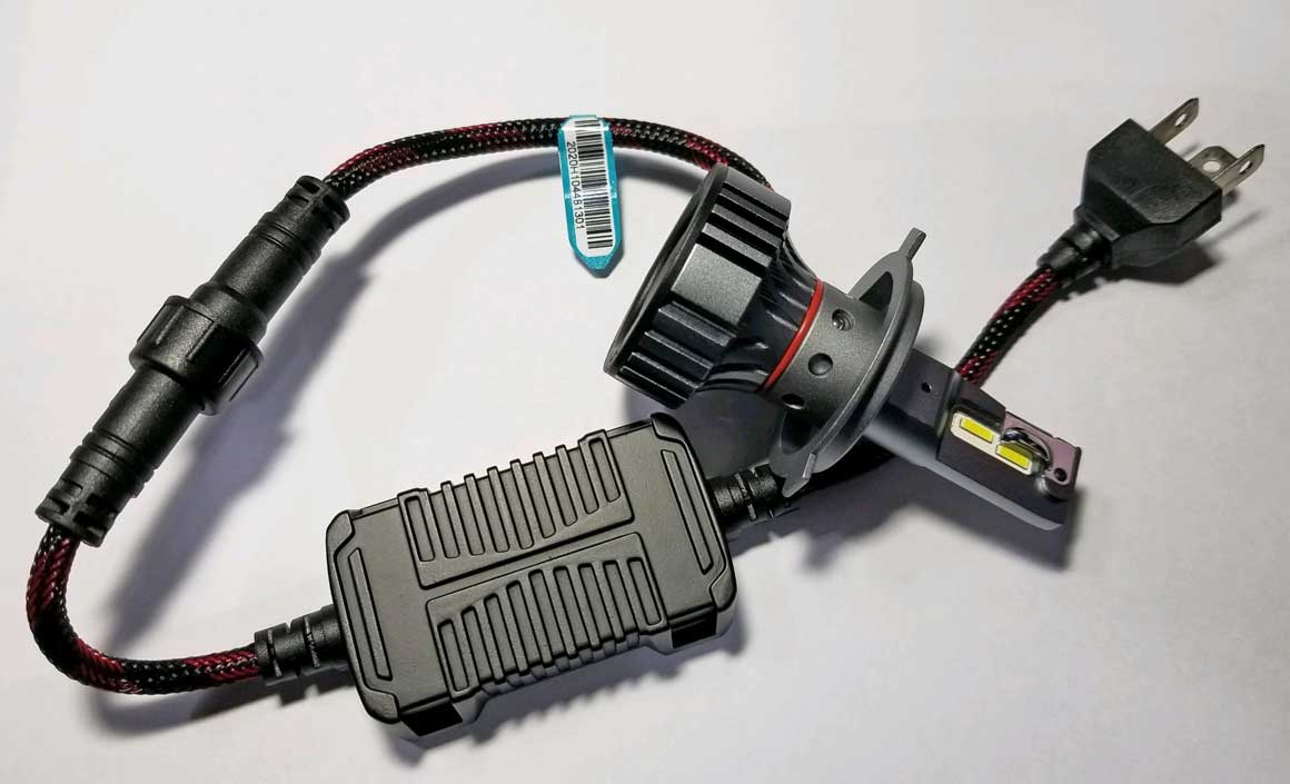
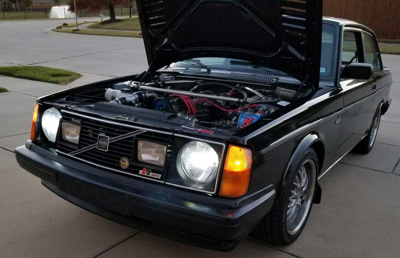
These two photos below were taken a little after sunset using low beams. The top image shows the 80/100 watt HALOGEN H4 bulbs I had been using. The bottom image shows the new GTR Ultra 2 LED bulbs. My observation is the LED bulbs are noticeable brighter than halogens. They have an equal or better beam pattern and a BETTER beam cut-off at the top. The light color is a bit whiter than the yellow-white color of a halogen. The LED color is advertised at 6000k white, so if you prefer yellowish lighting, I guess you can stay with halogens. After driving for a while, I found I really liked these LEDs and I've now been using them for a number of years. 
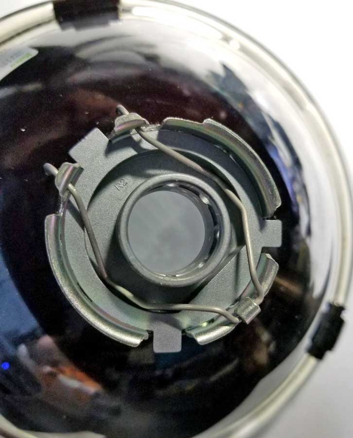
 New GTR Lighting Ultra 3 LED Bulbs New for 2025 If you've been wondering if high-end LED bulbs could get better, it seems that GTR Lighting has come out with there new Version 3 bulbs. My own previous testing above used GTR Ultra 2. Here's a comparison chart from Headlight Revolution showing a number of bulbs they've tested. It also shows their brightness testing compared to a stock halogen. The new GTR Ultra 3 sure looks a lot brighter at 928 Lux compared to 596 Lux for the Ultra 2. Here's a direct link for the H4 versions: www.headlightrevolution.com/GTR-Lighting-Ultra-3-H4 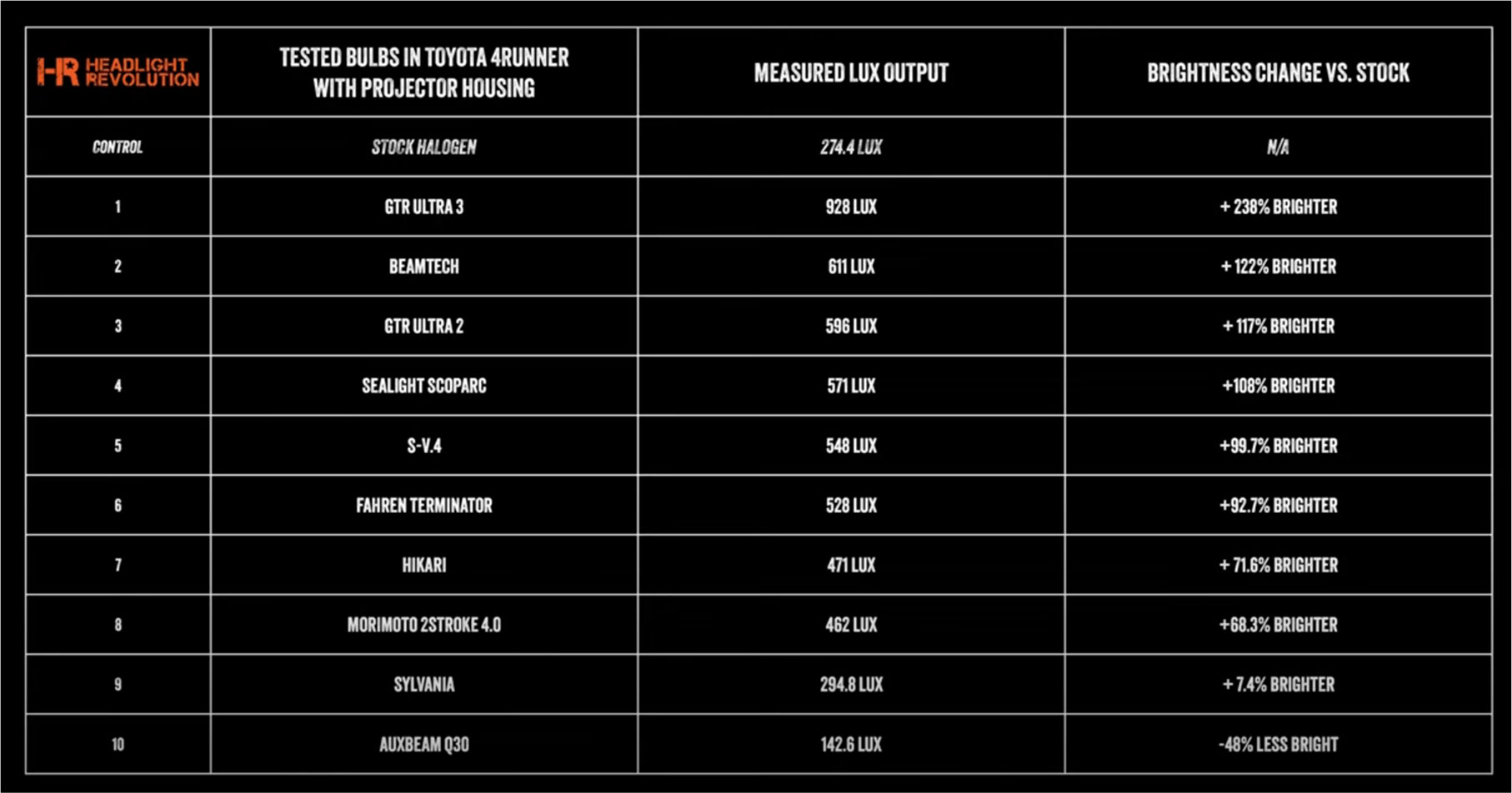 Here are two videos from Headlight Revolution from June 2025 introducing the new GTR Ultra 3 bulbs. https://www.youtube.com/watch?v=jEkfD37RIVo https://www.youtube.com/watch?v=XvArH0PQZGE Here are a series of test installation photos in an E-code headlight housing. Here's the S V.4 LED bulb, which I'll show being installed into the below Cibie H4 headlight housing. The collar shown below can be removed from the bulb. It just pulls off. Since the rear cooling fan portion on the bulb is a bit wide, removing the collar makes it easier to install the bulb after installing the collar. Those spring retainer clips below then can be locked down. 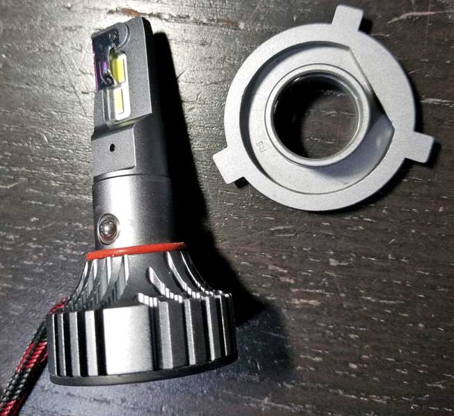
 This rubber dust boot came with these Cibie headlights. It gets installed over the collar. The center opening then needed to be stretched a little to fit over the raised center hole on that collar. 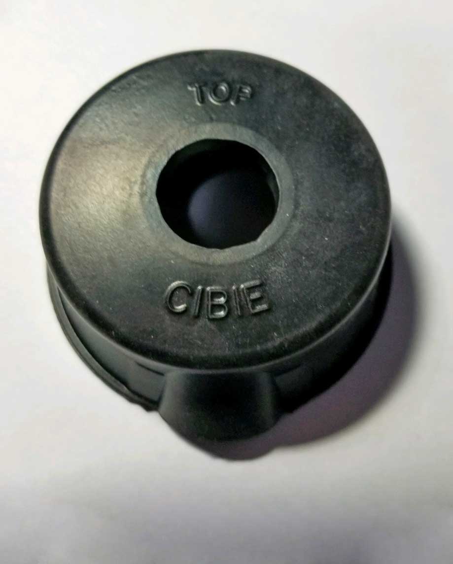
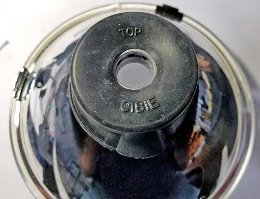 Then the bulb is inserted through the collar and just clicks into place in that collar. Pretty easy. 
 The bulb needs to be oriented so that the low beam CUP faces straight UP. That cup shields or limits light glare when low beams are on. The bulb can easily be turned in the collar for perfect alignment. This video below from June 2025 will reinforce this alignment requirement. It explains the final adjustment for GTR Lighting Ultra 3 bulbs, which are adjusted the same.. https://www.youtube.com/watch?v=v11IUM1PYH4 All done. Pretty slick setup. |
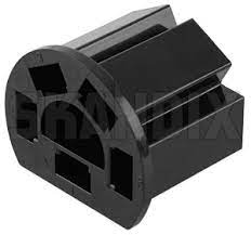
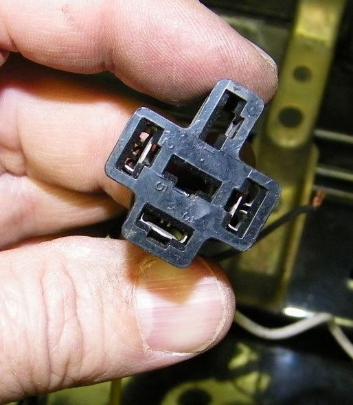
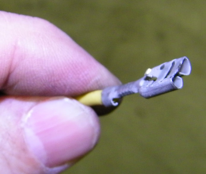
| How to Remove Terminals from 240 Headlight Sockets |
|
| Headlight Relay Harness Upgrades |
This
is a good project for anyone with any older Volvo, especially if you
have or want to to upgrade to brighter headlights with bulbs that use more wattage than factory. For some good old-school info, have a look at Daniel Stern's page on this
subject. He also has several useful diagrams for understanding how to design and
build your own headlight relay harness.
http://www.danielsternlighting.com/tech/relays/relays.html Here is a Volvo 240 specific diagram showing how an upgraded relay harness can be made. The relay triggers (relay are connected to and triggered by 56a and 56b) can be taken from the fender harness connectors or if you want to bypass the bulb failure relay, you could take those triggers from terminals 56a and 56b directly from the 5-pole headlight step relay connector. 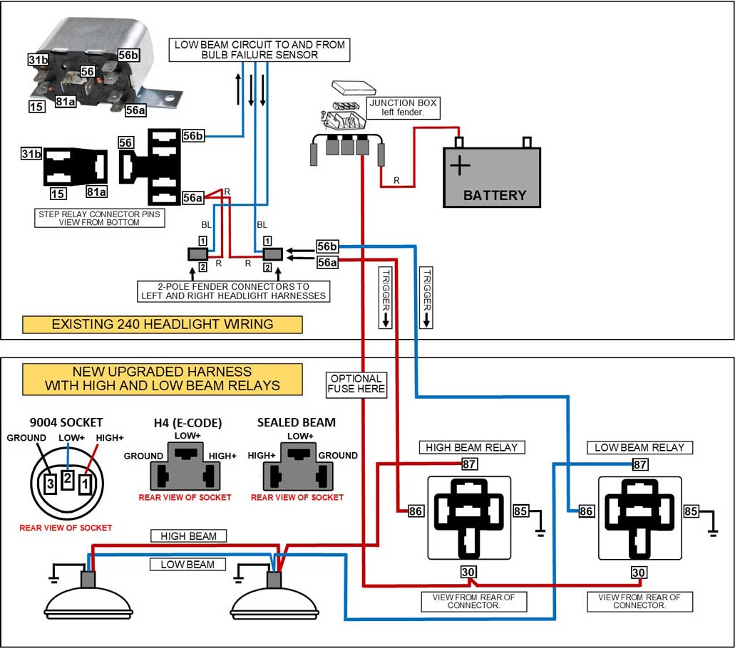 This diagram assumes you would use one relay to control both low beam headlights and another relay for the high beams. The above 9004 bulb socket came on all 1986-93 USA 240s. A European E-Code headlight will typically use an H4 bulb, which uses a different bulb socket. UPDATE 2018: Wagonmeister is offering ready made 240 headlight relay harnesses, like this one below. 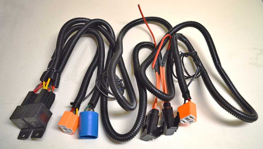 |
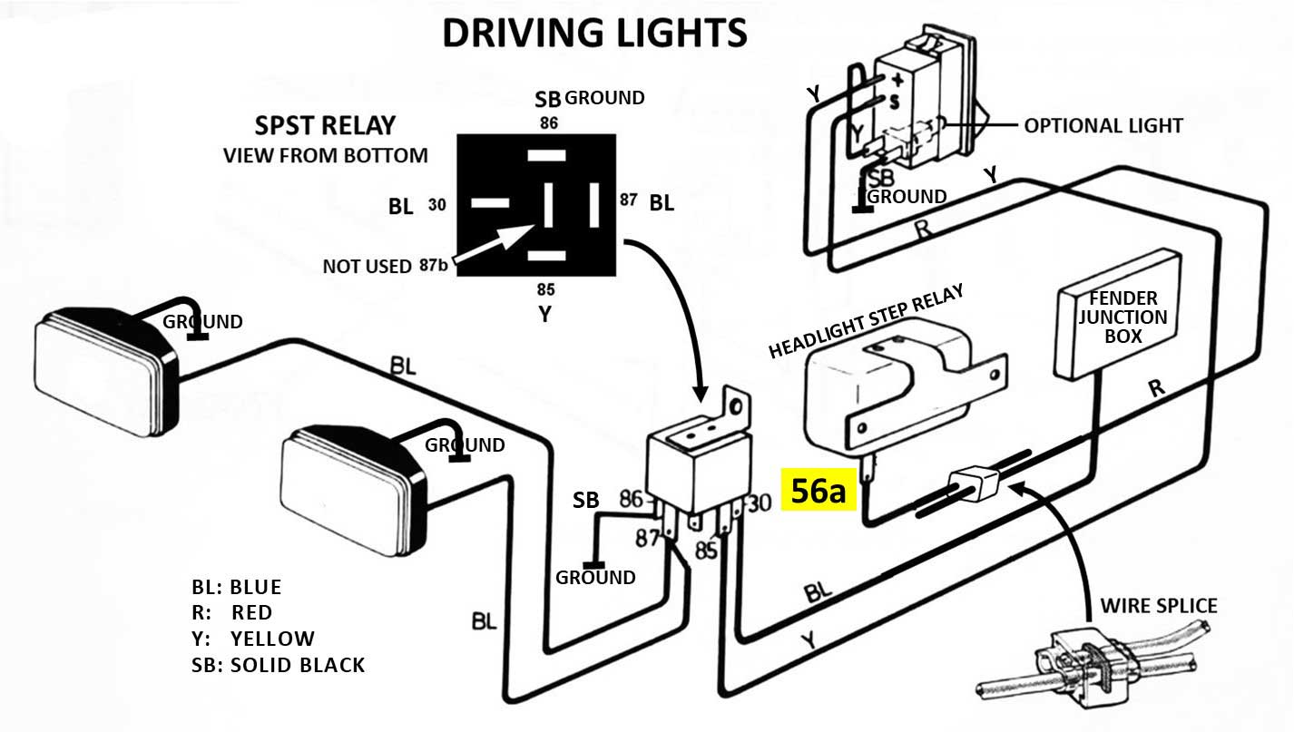
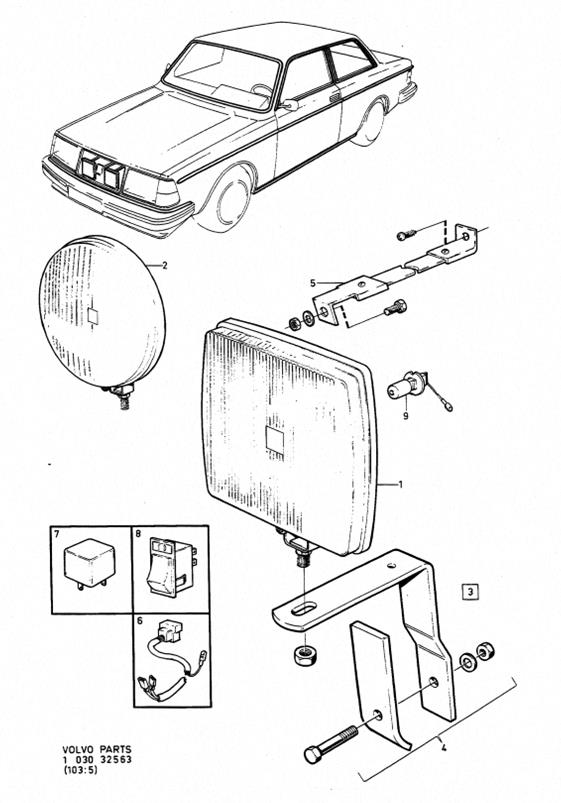
| 240 Fog Light or Driving Light Installation |
I found these
driving light diagrams below in some OLD Volvo
242 GT literature. I modified them for simplicity
and I decided to share them here. These diagrams
below will show you two different methods of
wiring; one for driving lights and one for fog lights. It uses a
dash switch in conjunction with the 240
headlight step relay and with an added cube
relay. There is a reason for wiring the circuit to the step relay. For Driving Lights, the diagram below allows the lights to be automatically cut off when you switch OFF your HIGH beams. For Fog Lights, the diagram allows the lights to be cut off when you switch ON your HIGH beams. The battery power is drawn from the inner fender battery junction box or it may be taken directly from the battery. A FUSE is recommended somewhere between the battery power source and the relay. |
|
|
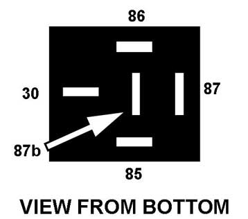
AUXILIARY DRIVING LIGHTS: 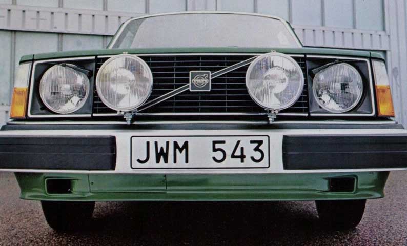 With this method, the AUXILIARY DRIVING LIGHT switch receives power from TERMINAL 56a on the headlight step relay. 56a on the step relay is the high beam output, so this means these lights will be configured as auxiliary high beam lights that will only come on when the dash headlight switch is turned on AND when the high beams are also on. When the driving light switch is turned on, it sends power to terminal 85 on the cube relay, turning the relay ON. So then turning ON your high beams will turn ON these driving lights, as long as the driving light switch is in the ON position. If the switch has a bulb as this one shown does, then it will light up when the driving lights are on if wired this way. |
|
FOG LIGHTS: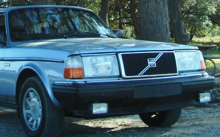 I modified this diagram to demonstrate a method for fog lights. With this method, the fog light switch receives power from TERMINAL 56b on the headlight step relay when your headlight switch is turned on. The switch sends power to terminal 85 on the cube relay, turning it ON. 56b on the step relay is the low beam output, so this means the fog lights will only come on when the dash FOG LIGHT switch is turned ON and when the low headlight beams are also ON. So then with this wiring, turning ON your high beams will turn OFF the fog lights. If the dash switch has a bulb as this one shown does, then it will light up when the fog lights are on if wired this way.
|
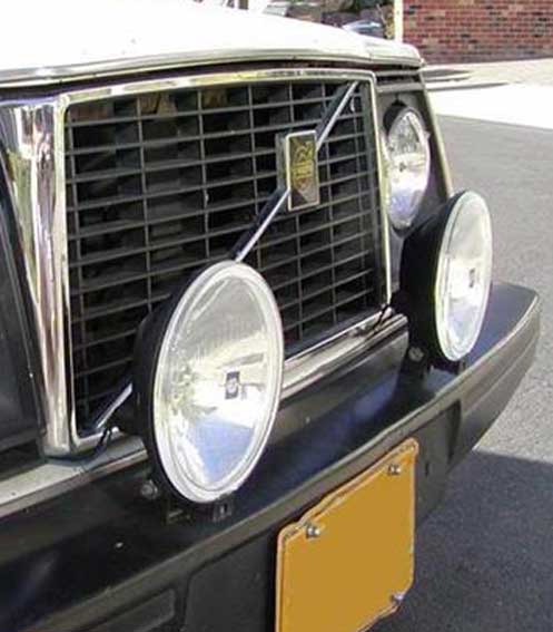
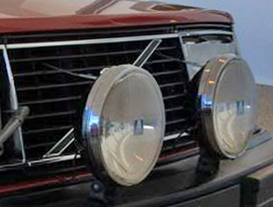
| Mounting Driving Lights on your 240 without Drilling your Bumper! |
ANOTHER GREAT IDEA Here's another method from a BMW owner in Germany. He used a 1.5 mm (0.060 inch) metal plate, which he mounted to the bumper using the license plate mounting holes. The plate is then hidden behind his license plate. He also added two small brackets at the bottom of the bumper to stabilize it.     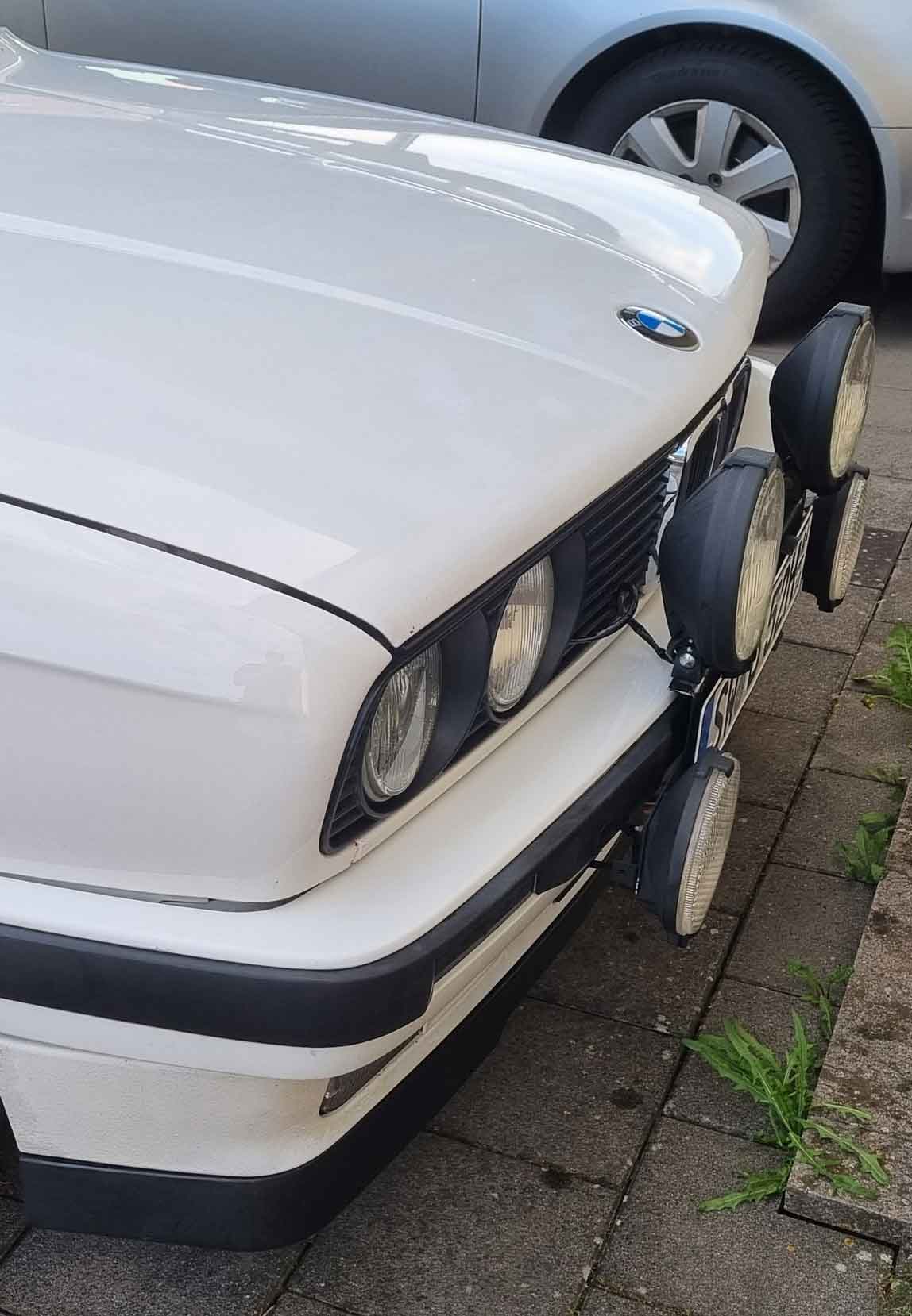  |
|
|
||||
| davebarton.com |
prancingmoose.com |
240turbo.com |
Special Emblems |
|
| Prancing
Moose Stickers |
Volvo
Stickers |
Body/Chassis/Engine
Labels |
240 MODS and FIXES Page | |
| Other Car Brand
Stickers |
Steering
Wheel Labels |
Center Cap Labels/Overlays |
Cool Volvo
Products |
|
| Grill Labels/Overlays |
Volvo Wire
Harnesses |
Conversion Harnesses |
Harness
Parts/Connectors |
|
| Volvo Relays |
Coil Repair
Harnesses |
240 Window
Scrapers |
740/940
Window Scrapers |
|
| Adjustable Voltage
Regulators |
Horn Buttons |
240 Odometer
Repair |
740 Odometer
Repair |
|
| Volvo Gauge
Faces |
740
Turbo/Boost Faces |
240 Black Door Vinyl |
850 Odometer
Repair |
|
| ALTERNATOR Page |
240 Power Mirrors - Switches |
240 Oil Cooler Page |
240 Fuse Panel Page |
|
| Group A
Racing 242 Turbo Page |
240 Hydraulic Clutch | Fuel Pump RELAY Page |
240 Headlight RELAY Page |
|
| Used Parts & Extra Stuff for sale |
CRIMPING Page |
240 Ignition Page |
240 Headlight Page |
|
| 240 Gauge Electrical Diagrams | 240 REAR END Page | Yoshifab Catch Can Install | 240 TAILLIGHT Page | |
| Side Marker
Lights Page |
Gentex Mirror Upgrade | Yoshifab Drain Tube Install | Modified 240 Favorites | |
| SoCal Salvage Yards | Unleaded Racing Fuel | B26FT Stroker | Dave's 245 Spec Page | |
| 240 SUSPENSION Page | 240 Lowering Page |
240 Windshield Page |
240 WIPER Page | |
| 240 BRAKES Page |
240 Dash Top Gauge Pod | Cadillac 4-Note Horn Install | 240 DYNAMAT Installation | |
| 4 Speed Fan
Controller |
Electric Cooling Fan
Page |
BRUSHLESS Cooling Fan Page |
Tropical Fan
Clutches |
|
| 240 AC Page | "KOMFORT BLINKER" Upgrade | T5 Trans Conversion Page | 240 Engine Mount Page | |
| 240 VIN Page | Stepper Idle Valve Page |
Vacuum Diagrams | 240 HOOD Page | |
| 240 Exhaust Page | 242 Power Vent Window Project |
EFI Volvo Pin Function Diagrams |
Favorite Links | |
| R-Sport
Apparel |
Prancing
Moose Apparel |
Volvo Meet Photo Albums | Texas Volvo Meets and Events | |
| Ordering Instructions | Policies | PAYMENTS Page |
Mojave Road Trail Map Page |
|
| Returns | Shipping | Shopping Cart Troubleshooting | Contact Us |
|

|


 alternators are known for poor voltage.")


