|
2 4 0 T U R B O . C O M D A V E ' S V O L V O P A G E
|
||||||||||||||||||||||||||||||||||||||||||||||||||
|
2 4 0 T U R B O . C O M D A V E ' S V O L V O P A G E
|
||||||||||||||||||||||||||||||||||||||||||||||||||
| This page is intended to help and inspire those of you who bought one of these Group Buy Vacuum Formed Gauge Pods. If you didn't buy one, find someone who has one and do this work to it.
 |
|
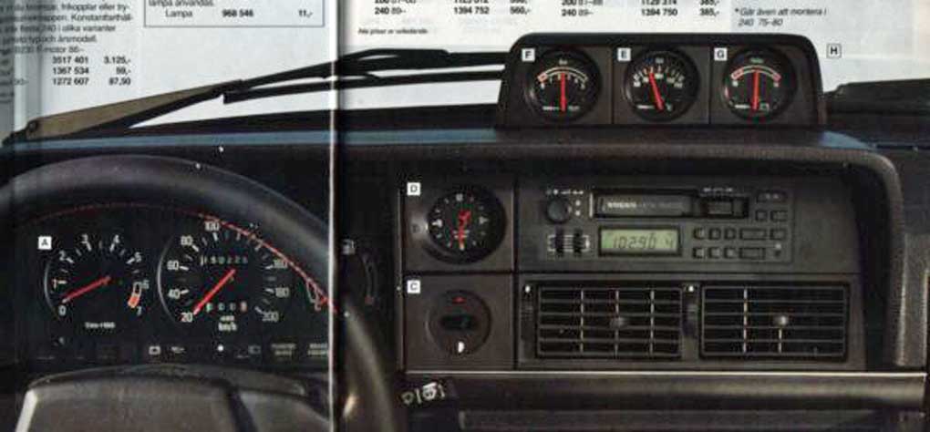
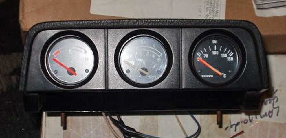
| Let's get started . . . . . In 2017 I bought a vacuum formed plastic gauge pod that was made by a Turbobricks member as part of a group-buy. The new plastic pod was originally intended to replicate (or at least to be fairly similar to) the rare and expensive original Volvo 3-gauge pod shown in these catalog page and other images below. This original pod was an accessory Volvo offered at one time for the dash top in a Volvo 240. The new vacuum formed replica was supposed to be close to the same shape as the original and it was to include a front overhang (like shown on the original). |
|
 |
|
|
|
|
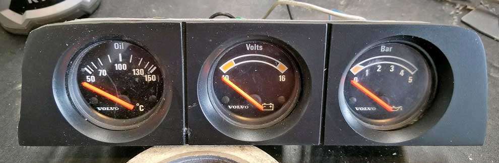
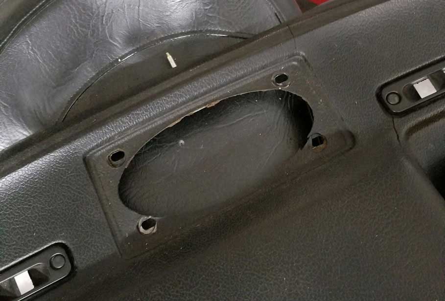
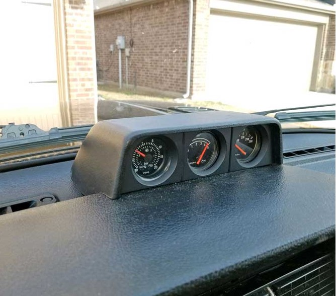
| For those of you unfamiliar with the original Volvo 3-gauge dash top pod,
here are some photos below. The original Volvo pod was to be
mounted on the dash over the center speaker grill opening. The
plastic speaker grill gets removed first and the pod then gets bolted down,
covering the speaker grill hole. |
|
      |
|
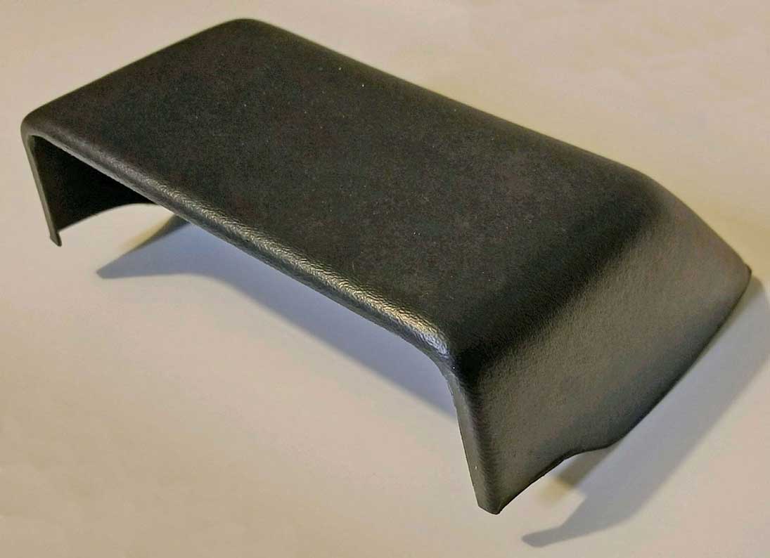
| GROUP BUY VACUUM FORMED POD |
|
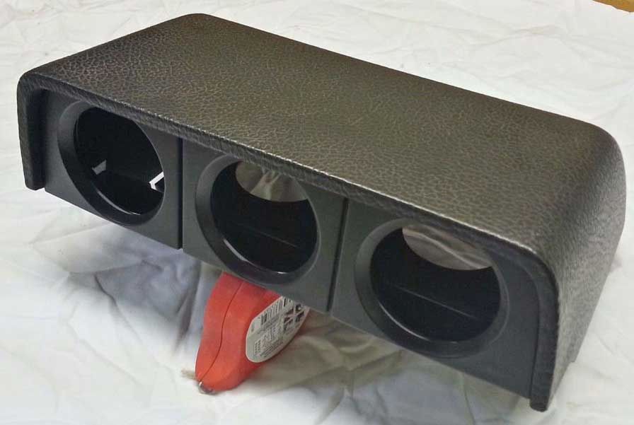
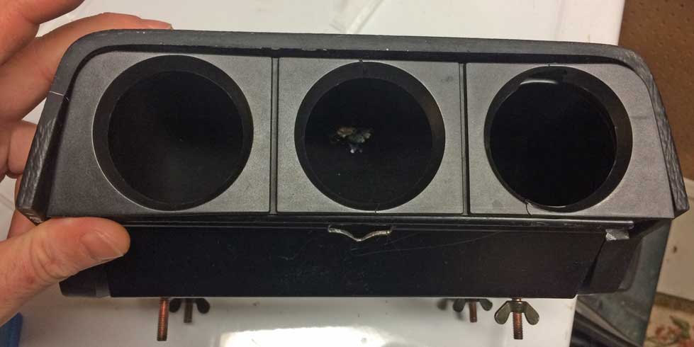
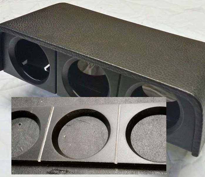
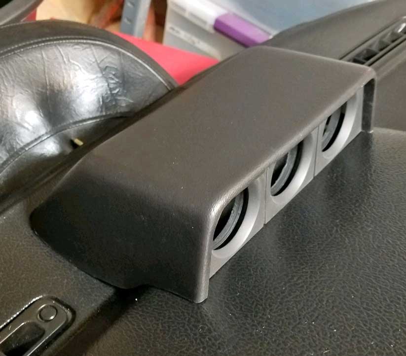
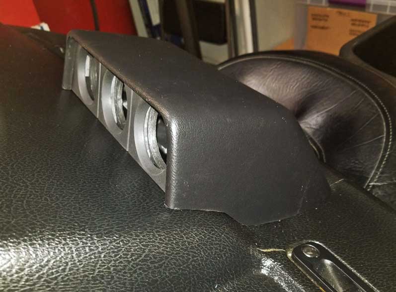
| When the group buy vacuum formed
pod was finally presented to the group, it turned out to be not quite what I expected.
There
was no front overhang and there was an unsightly flange along the
bottom, intended to be used for mounting with 2-sided tape. While
this photo below isn't the
exact pod I
received, the one I got was exactly the same.
|
|
|
|
|
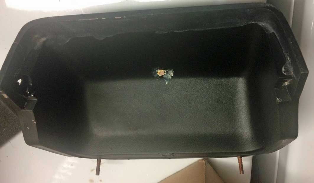
| I would never put the above pod on my dash the way it was, so
cutting it up didn't pose much of a concern to me if it got
ruined. So I decided to try some modifications to see if I could make it better. |
|
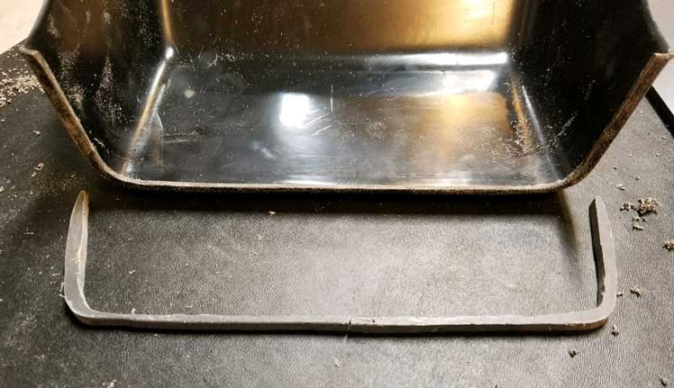
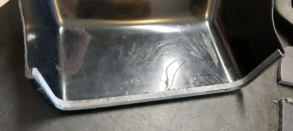
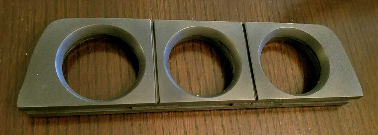
| I began by trimming the front area to create the front
overhang found on the original part. I didn't have any fancy saws, so I
simply used tin snips and a bench grinder for most of the trimming
you'll see in this page. I just went slow and took lots of measurements.
I also had a spare 240 dash so I could frequently test fit this. |
|
  As you can see, I also carefully trimmed off that big OUTER bottom LIP that sat on the dash. Again, all this was done slowly and gradually on a simple bench grinder with lots of test fits on my spare dash. |
|
|
|
|
| Then I decided I needed to beef up the front lip, so I cut out a piece of PVC plastic that I glued into the front opening. That PVC plastic can be found at McMaster Carr: https://www.mcmaster.com/#catalog/123/3637/=1ajvxvt PN 8747K114, 12 x 12 inches x 1/4 inch thick. About $10 plus shipping. They have lots of other thicknesses and sizes too. |
|
  This PVC plastic is pretty easy to shape using a bench grinder. The photo below shows the new piece sitting behind the front lip and glued in place. 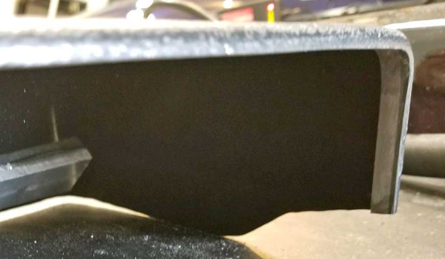
|
|
|
|
|
Most
gluing was done using Gorilla 2-part epoxy for plastic. It says
it sets in 5 minutes. Don't believe it. It actually takes longer. Most of the time I let it dry until the next day.
|
|
|
|
|
I found that there was a small unsightly warp in the back slope, so I glued on a brace made from a piece of 1/4 inch PVC.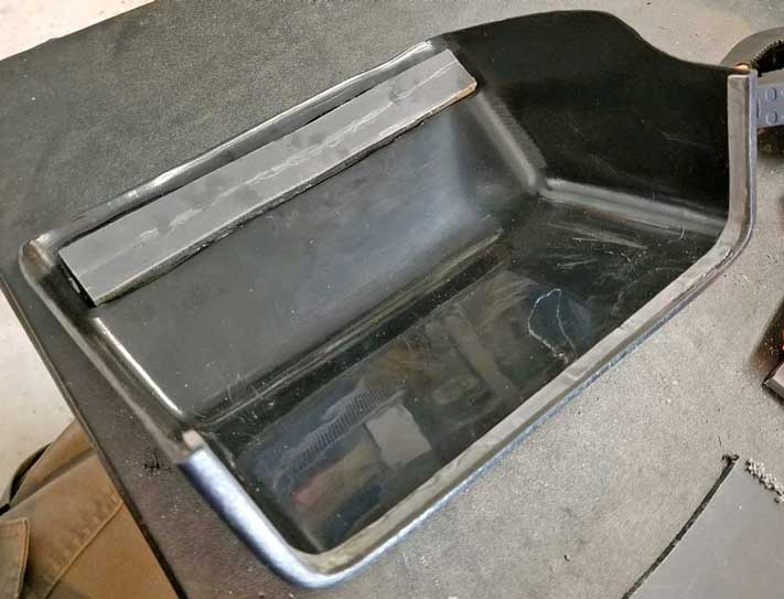
|
|
|
|
|
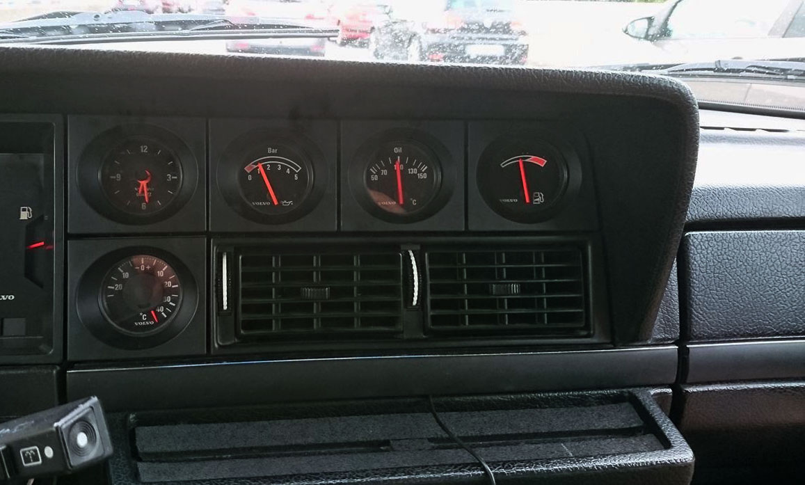
| I cut a front face piece out of 1/4 inch PVC. The basic idea here is to
cut three holes and then bevel them to look like how the original pod bevels look. At this point I had the choice of making this so the gauges would be angled toward the driver, like the 240 Turbo three gauge panel in the dash, or I could leave them facing straight, like the original Volvo dash pod. I chose to leave them facing straight. The reason for choosing to mount gauges straight is that this pod sits further from the driver, plus the gauges to the left of the 240 Turbo three gauge panel in the dash are not angled and those look fine that way. 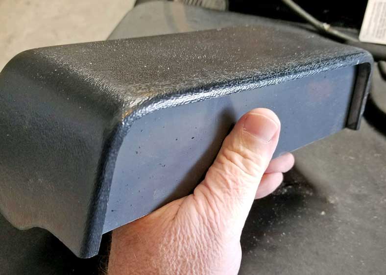
|
|
|
|
|
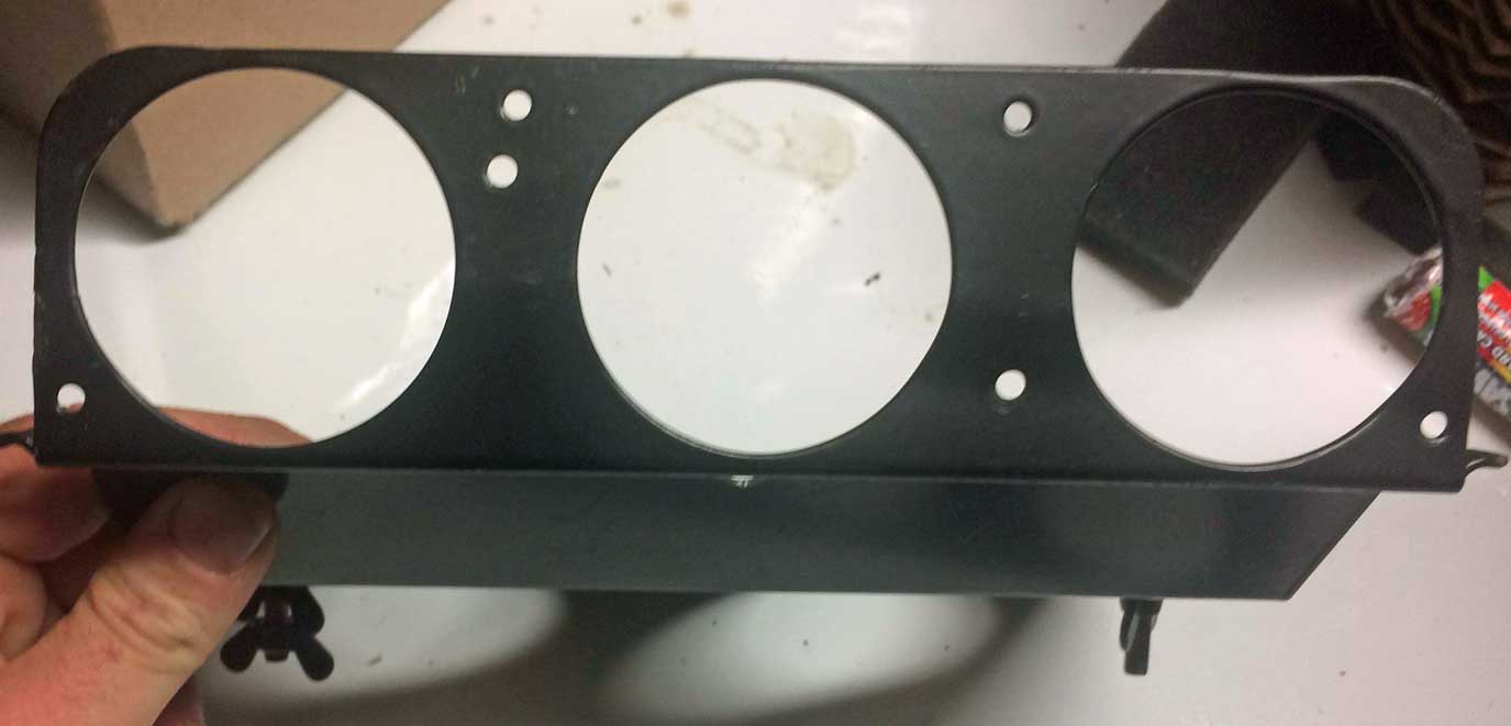
| So I bought TWO HOLE SAWS. | |
I bought a 2 1/16 inch (2.0625 inch) hole saw because I knew it would be needed to cut holes for the the 52 mm gauges
to slide into (you'll see more details on that later). This piece with
larger holes is a 3-hole mounting piece BEHIND the front 3-hole face. The rear mounting piece is below
 And I also bought a 1 7/8 inch (1.875 inch) hole saw. I'll talk more about this one first below. 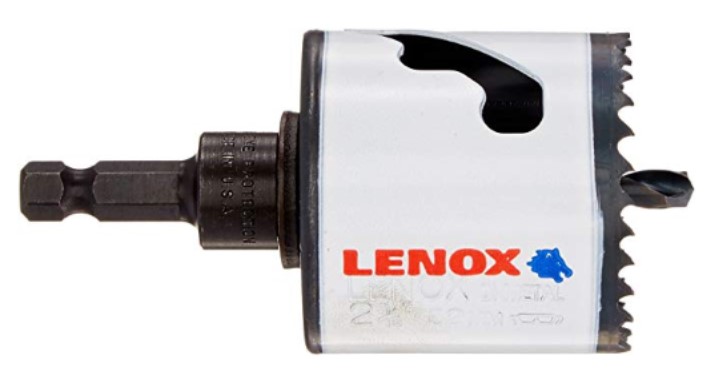 |
|
|
|
|
| The reason for using the 1 7/8 inch (1.875 inch) hole saw: After careful measurements of some 240 VDO gauges and looking at photos like this one below of the original Volvo gauge pod
(and measuring the relative height of the outside edge of that bevel you can see here), I began
thinking about how I could replicate the beveled holes on the front face to look like the original. I
decided 1 7/8 inch was the right
size hole to look like the original hole size before adding a bevel. This size would allow the same amount of the outer edge of the gauge to be
seen through the hole. So the 1 7/8 inch hole would be cut first on the front face piece. Then the bevel would be made using a bevel router bit. The
outer diameter of the finished bevel really needed to fit in the same
overall height of the front panel just like the original pic at
left. I wanted to be sure. So measure twice, cut once. 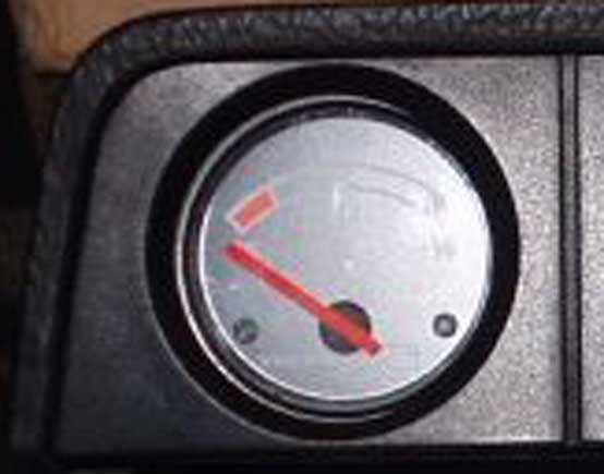 After some measuring and deliberation, I decided that the bevel would need to be 30 degrees to appear correct with the 1/4 inch PVC I was using. So I bought this 30 degree router bit with a ball bearing below. 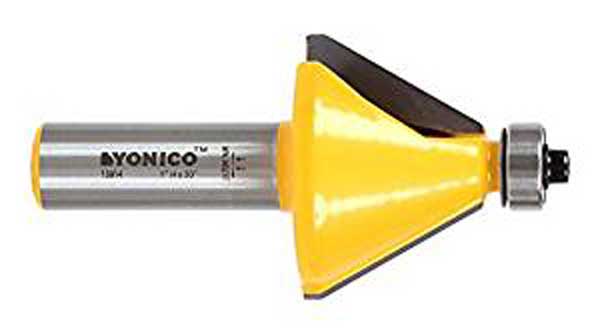 I don't own a router and I didn't plan on buying one for this one-time use, so I rigged a way below with my drill mounted in a vise. |
|
|
|
|
|
So the below pics are of the front face piece, made from 1/4 inch PVC,
which is attached to a jig I made from scrap pieces of PVC. The jig will hold the PVC front piece for the hole cutting step and then later for the bevel cutting step.. The black marker line I drew around the edge of the front face shows the limit of the area that will actually be visible inside the front overhang on the outer shell when assembled. Before using the hole saw I drilled three pilot holes. |
|
 The raised recess on the bottom of the jig (seen below) was made so that after the holes were cut, this assembled piece could be placed flat on my bench, so the front face piece would be raised up off the bench to give that ball bearing on the router bit some room to be guided along the inside of the 1 7/8 inch holes when the bevel cutting step began. These PVC pieces were all 1/4 inch thick. 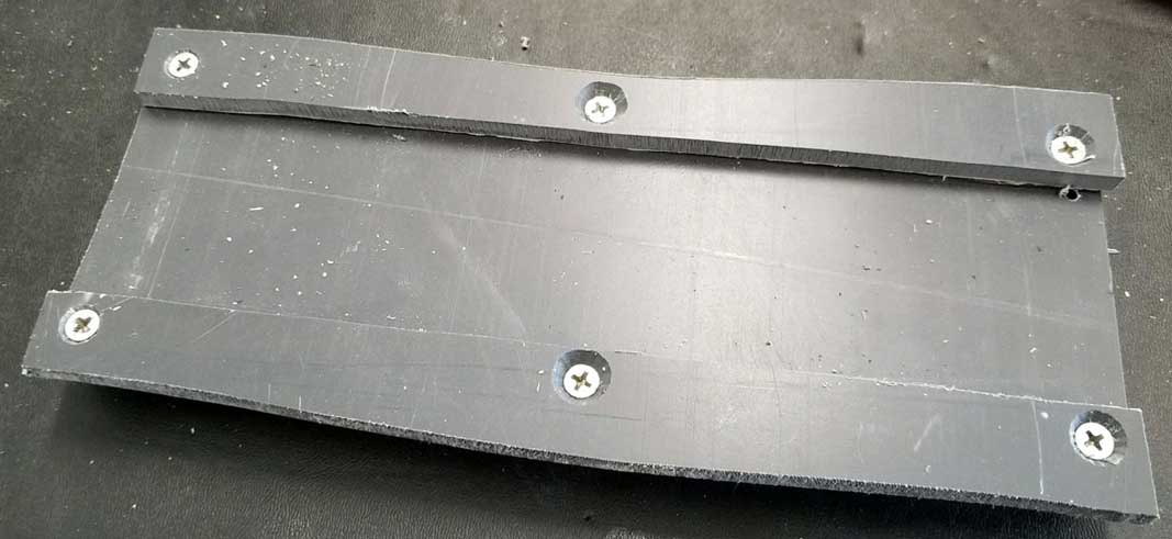 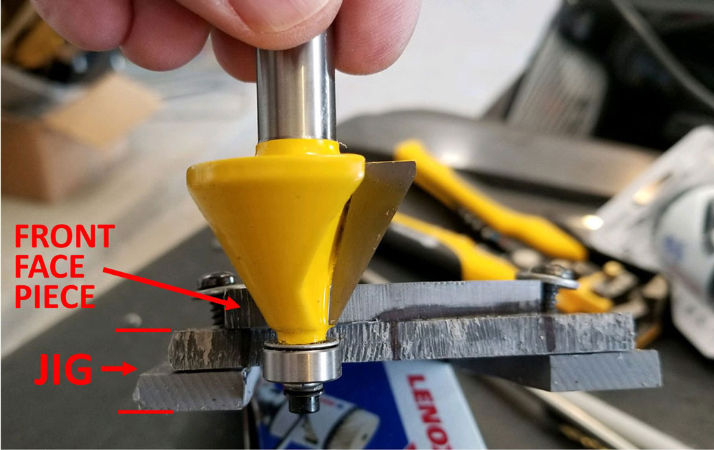 |
|
|
|
|
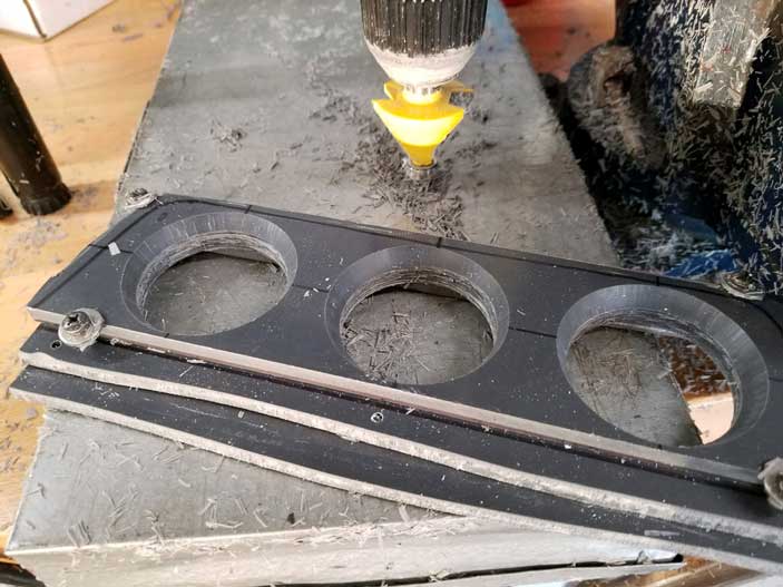
| Using the 1 7/8 inch hole saw FIRST, I cut the three 1 7/8 inch holes through
both the front face and jig assembly all at once. This hole saw step is not shown below,
but you can see the raw holes that were cut through both PVC layers
below. Then I set up a drill mounted in my bench vise for stability to begin the BEVEL steps. It's certainly not perfect. A drill press would have been a very handy tool to have, but I don't own one. 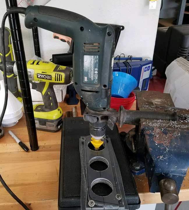  |
|
|
|
|
| It
took some time to cut these bevels. Probably 10 minutes per
hole. I had to go slow and gradual
because the router bit (which is made to cut wood) tended
to want to grab too much of the plastic material at once and the
entire jig wanted to jump around if I tried to go too fast. So I went
very slow and the holes were cut nice and even and somewhat smooth, but not smooth enough yet. In this photo below you can see how the bottom PVC layer on the jig was used to help guide the router bit ball bearing. It worked great. |
|
 Here's the front piece after I separated it from the jig. Right now this piece is a bit rough looking. The bevels will need some finish work. 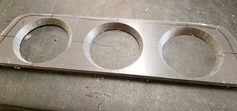
|
|
|
|
|
| BEVEL SANDING BEGINS Then I began sanding the bevels to smooth them out. First I started hand-sanding using a piece of sandpaper, but I wasn't happy with the slow progress. Plus I wanted the sanding to not damage that precise 30 degree angle. So I bought this 60 degree PLASTIC FUNNEL in the first pic below and wrapped my sandpaper around it. The 60 degree funnel has precisely the same angle as the 30 degree bevels. |
|
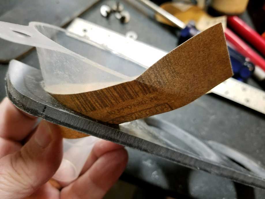 Sanding went much faster this way. I began with 150 grit sand paper and progressed through 220, 320 and finally 600. 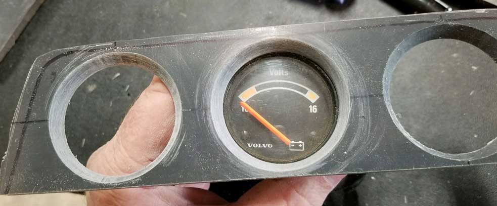 This pic below is after sanding with 600 grit and then giving it a quick coat of black paint to see how it looked. Looking pretty good. But it's not done yet. 
|
|
|
|
|
| Creating the vertical cuts on the face. | |
| Then
it was time to add the two vertical cut lines between the holes, like you see on the original pod below. I carefully measured as close as I could and stared at the pics of the genuine Volvo pod. I determined that those cut lines seemed to be between 1/16 and 3/32 of an inch wide. So I stacked two 12 inch hack saw blades (24 TPI blades) on my trusty hack saw and I found they were just over 1/16 inch wide combined, a good width. I scribed the two lines on the face plate with an awl and put 3 layers of tape on each side to protect the front from getting accidentally scratched. Then, going nice and slow to avoid a disaster, it took about 5 minutes to slowly cut each line to about 1/16 inch deep. |
|
|
|
|
|
|
| The
cuts shown below are about 1/16 inch deep. You'll see later I changed my mind and made them deeper. The paint I used on the pod OUTER SHELL is SEM Semi Gloss Black (Classic Coat). That's what I have used on my dash parts before and it looks good. The face plate is painted with a different paint than the pod. In this photo below I experimented first with some SEM Trim Black, but I didn't like it because it looked a bit too glossy compared to other dash gauge face pieces in a 240. |
|
 I later changed the face plate to Testors Flat Black, which was a bit TOO FLAT, so I then used a polishing pad to very lightly buff it to the right tone. Click HERE for that or scroll down below.  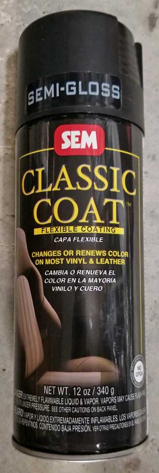 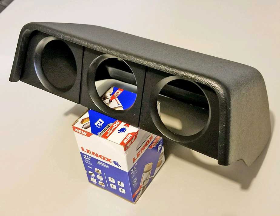
|
|
|
|
|
| I later returned to the face plate and made the vertical cut lines deeper (about 3/16 inch instead of 1/16). I did this after comparing
the 1/16 inch deep cuts I did first to the original Volvo pod pic below. The original slots looked a lot deeper than 1/16 inch. You'll see more info about this further below where I also found I needed to reinforced the back of this front face, so the deeper cuts wouldn't make it too fragile. |
|
|
|
|
|
|
| Creating some gauge mounting structure pieces BEHIND the front face for holding the three gauges. | |
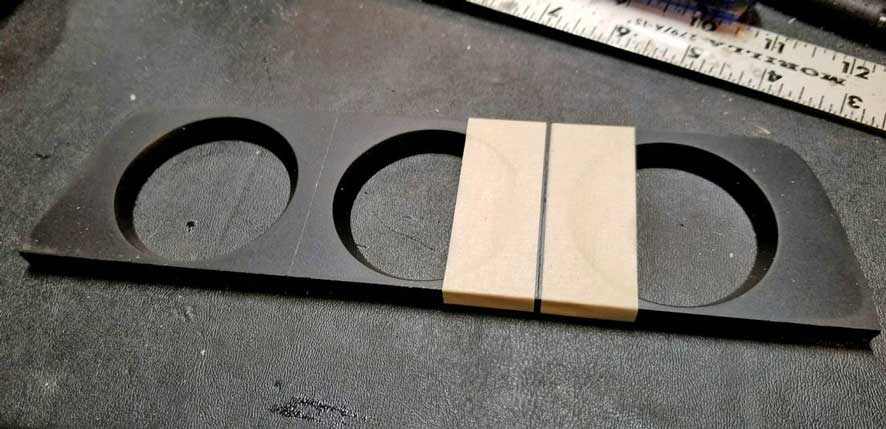
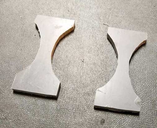
| Here is a series of pics showing two shaped SPACERS I made using 1/4 inch PVC, which are made to help hold the gauges in place. I used a bench grinder to contour these. | |
I then made a rear gauge holder plate from 1/4 inch PVC, which will sit BEHIND the front face plate I had already made. This rear gauge holder plate got three 2 1/16 inch (2.0625 inch) holes to fit the outer barrels of the three VDO gauges. If you're curious how I lined up the three holes to the exact same places as the front face plate, I drilled the pilot hole centers on this back piece at the same time I drilled pilot holes on the front face piece before using the hole saws on anything. 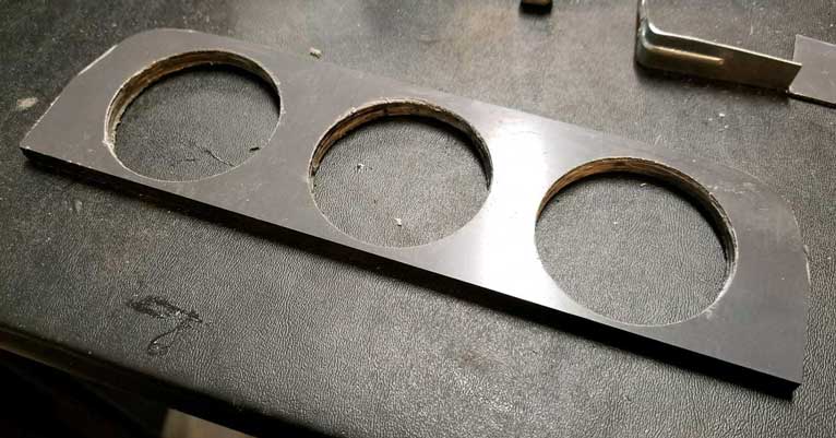 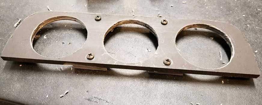 The two shaped SPACERS are designed to be attached to the rear gauge holder plate using the shown screws. These spacers will then be glued to the back side of the FRONT face plate. This way the gauges are sandwiched between the FRONT face plate and this rear plate and they can be removed by removing these four screws on the rear of the rear plate. 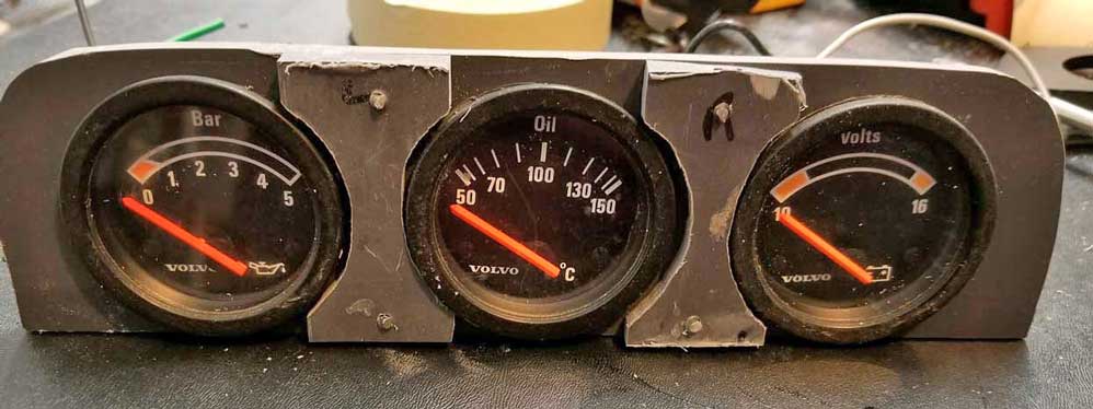
|
|
|
|
|
| Here the shaped spacers are being glued (not screwed) to the FRONT face plate (bottom piece in this first photo is the front plate). Gluing PVC plastic like this works well with PVC cement seen below. |
|
 The FRONT plate is shown below again with the shaped spacers glued on. These spacers also serve to reinforce the FRONT plate, because the vertical slots will be increased to 3/16 inch and that could have made this plate too fragile without reinforcement. 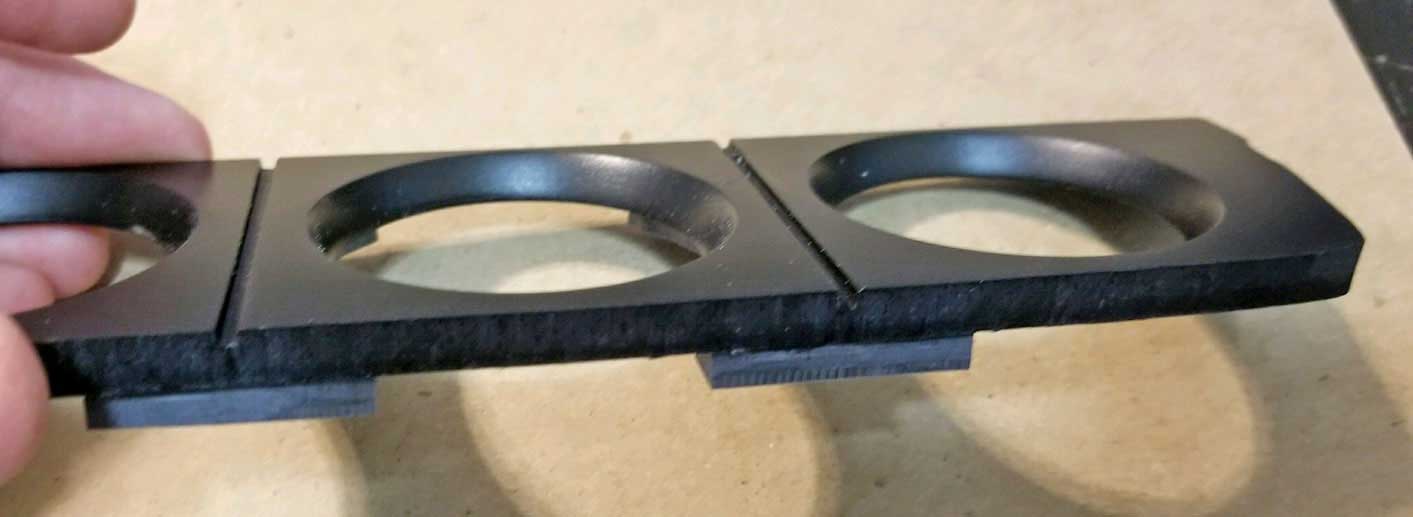 PVC Primer and PVC Cement.  |
|
|
|
|
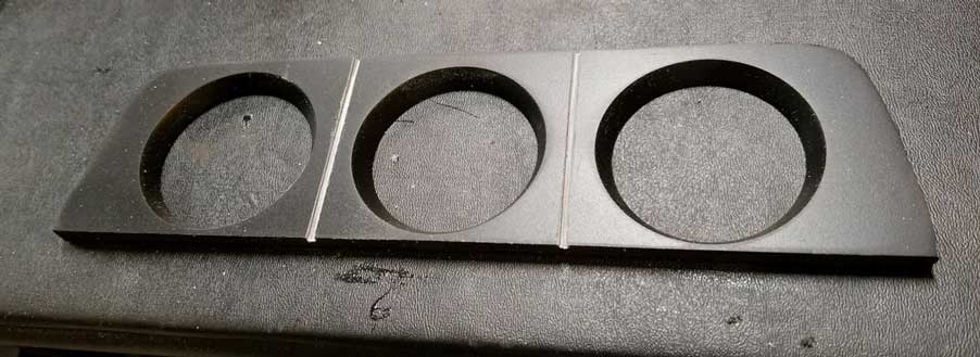
| After
gluing the spacers to the FRONT plate was done, I assembled the front and rear pieces
to see how they fit together. Looking good so far. The final pic below is after the vertical slots were cut deeper to 3/16 inch. |
|
 These spacers glued onto the FRONT face plate serve to reinforce the front plate to keep it strong after cutting deeper slots. Final paint has not yet been done at this point.  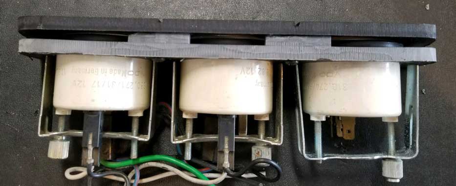 This pic below again is after the slots were cut deeper. 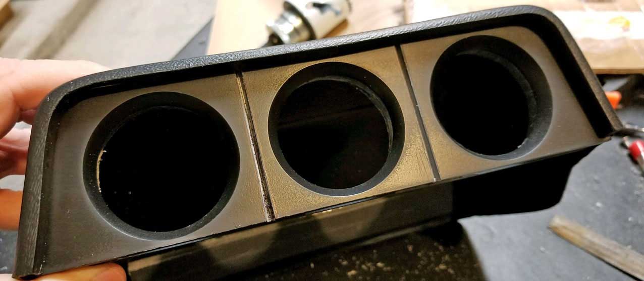
|
|
|
|
|
| Front face painting and finishing work. | |
| After cutting the vertical slots deeper, I noticed the bottoms of the slots
appeared a bit rough. So I mixed up some plastic epoxy and I carefully put
it in the bottoms of the slots using a toothpick. This can be seen in the first pic
below. The epoxy slowly leveled out and helped smooth the bottoms of the
slots. Then I sanded and painted the front surface using Testors 1249 Flat Black aerosol model paint. |
|
|
|
|
|
|
 <<< This Testors 1249 Flat Black aerosol
was the closest paint I found to get the right flat black. I chose this because I thought it was closest to a match of the
original Volvo dash front plastic. But this paint is ULTRA FLAT (no shine at all) and I later decided it still needed some work to make
it closer to what I wanted. <<< This Testors 1249 Flat Black aerosol
was the closest paint I found to get the right flat black. I chose this because I thought it was closest to a match of the
original Volvo dash front plastic. But this paint is ULTRA FLAT (no shine at all) and I later decided it still needed some work to make
it closer to what I wanted. So I bought this three pad assortment below of polishing hand pads.
Mirka Mirlon 4.5 x 9 inch pads in grits P360 red, P1500 grey and P2500 gold: https://www.amazon.com/gp/product/B001BKXWLC/ Since this flat paint was ultra flat, I did some very light buffing with the P2500 fine polishing pad, which slowly added a little bit of sheen to the flat finish. It created a really good match to original Volvo black plastic gauge face pieces.  |
|
|
|
|
| Creating a mounting method for the front face gauge assembly. | |
| Two-part
epoxy was used during these steps. I found that roughing up the inner
surface of the ABS shell with sandpaper in all places where epoxy was
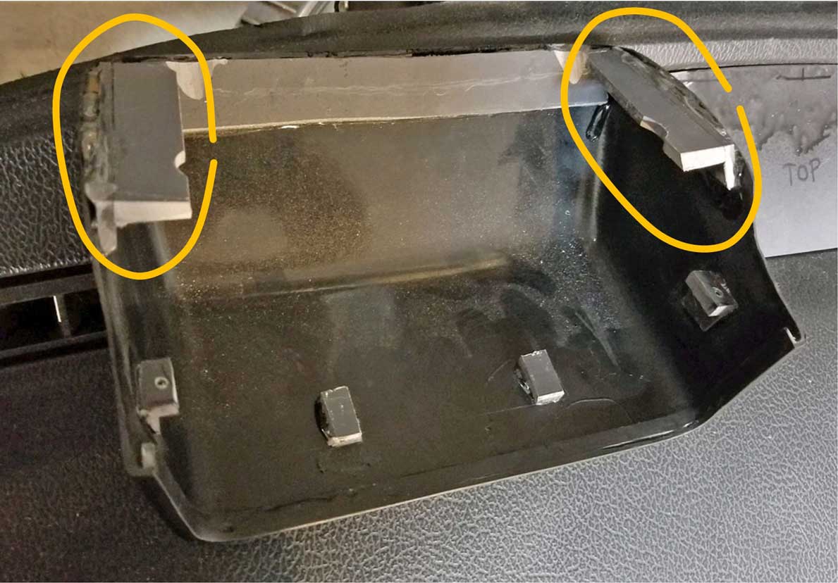
used helped it to stayed glued. Here below is where I began making some the mounting points in the outer shell to hold the front gauge assembly in place. In the first pic below I have glued in small feet to the shell to hold the back of the gauge assembly tight against the front lip overhang. These small feet pieces are made from 1/4 inch PVC. 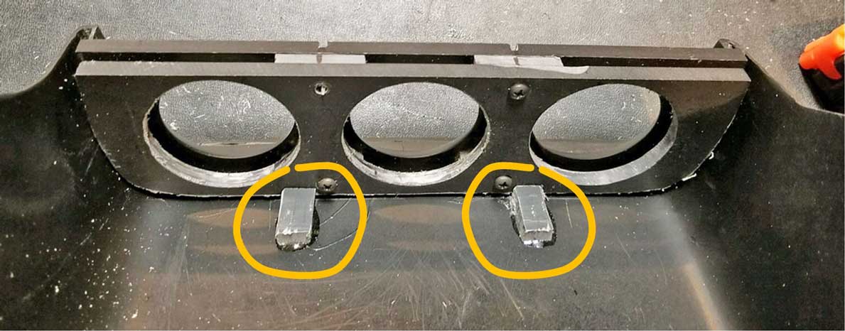 In this pic below I show where two more mounting point locations on the left and right will be added. One on each end of the gauge plate assembly. They were also glued to the outer shell. |
|
 These two pieces below were shaped from PVC and glued onto the outer shell using epoxy. 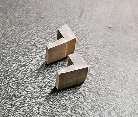 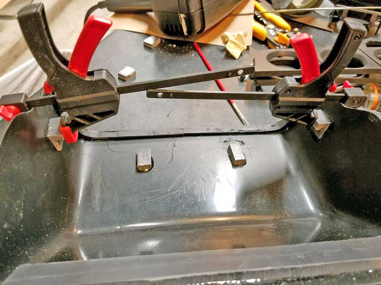
Then I made these new pieces BELOW to be glued onto the back of the REAR gauge mounting plate. 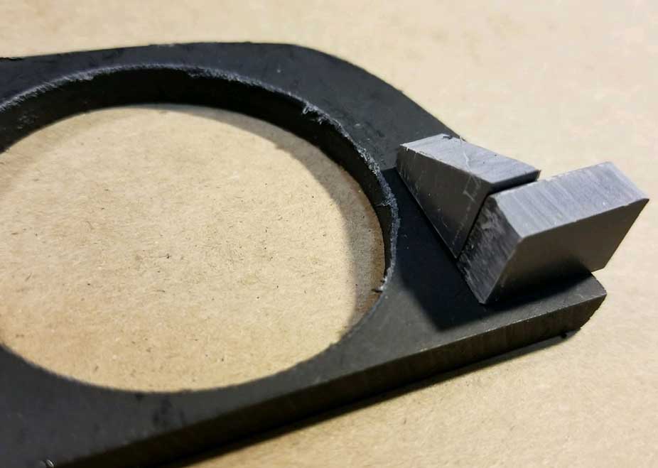 Then I drilled a couple holes for the two screws BELOW going into the right and left mounts. 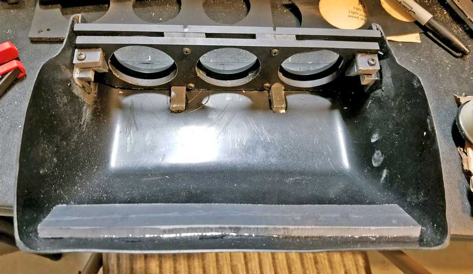
|
|
|
|
|
| Mounting the new pod to the dash top. | |
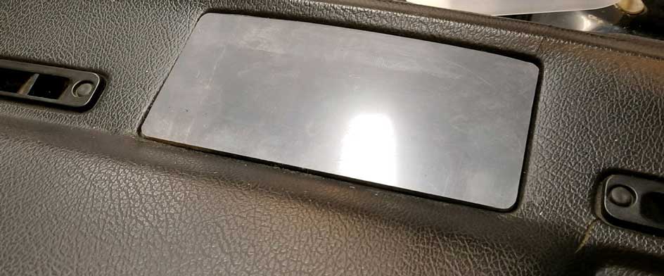
| I used an old spare dash for test fitting. That was a big help. I shaped a piece of 1/4 inch PVC to fit in the recess for the center speaker grill. As mentioned before, a bench grinder works well to shape PVC plastic. This speaker grill is in an early-mid dash like in my '84 240, but this speaker grill hole was eliminated in late 240 dashes. I didn't have a later dash to show. |
|
|
|
|
|
|
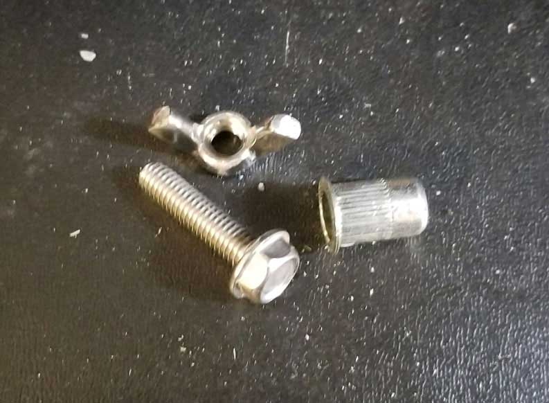
| This next section involved some experimentation and then some changes. I used some threaded rivet nut inserts with some simple 8 mm bolts and 8 mm WING NUTS. This was my original plan, but I changed my mind later and did it a bit different below. |
|
  BOTTOM VIEW BELOW SHOWING WING NUTS, which I later discarded after I found these tended to vibrate loose. 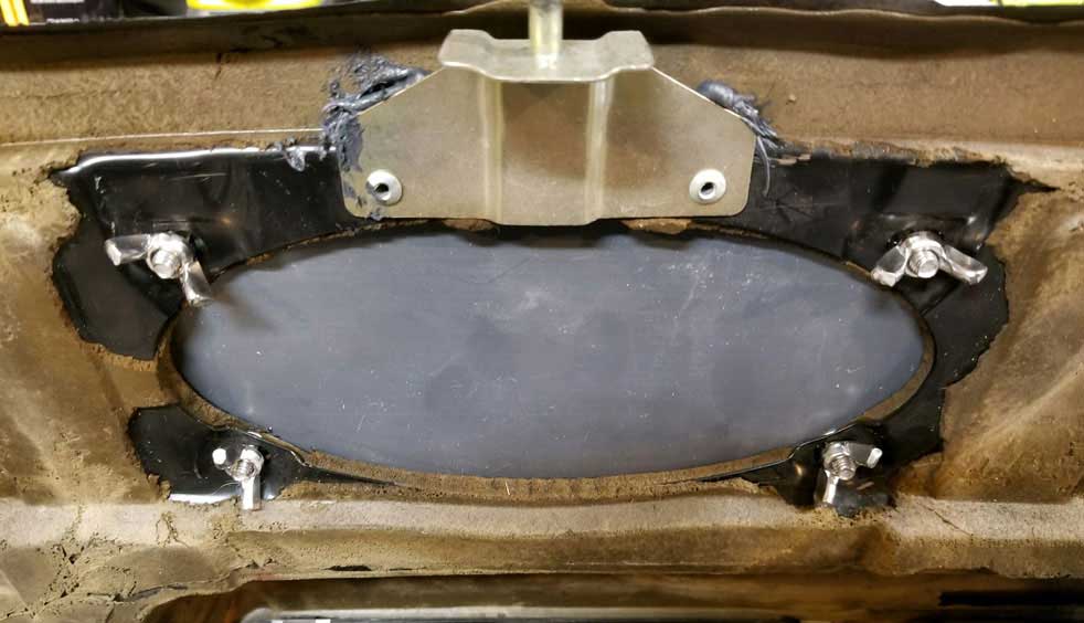
|
|
|
|
|
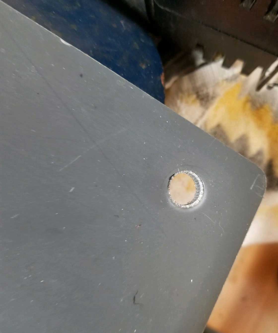
| Changing to something else. I removed the threaded inserts and used simple 8 mm flange nuts and I pressed those into the holes I had already drilled. These holes are about 3/8 inch and these nuts fit great. Then I used some different, lower profile 8 mm bolts with round heads. These were a better fit. |
|
  BOTTOM VIEW ABOVE. TOP VIEW BELOW.  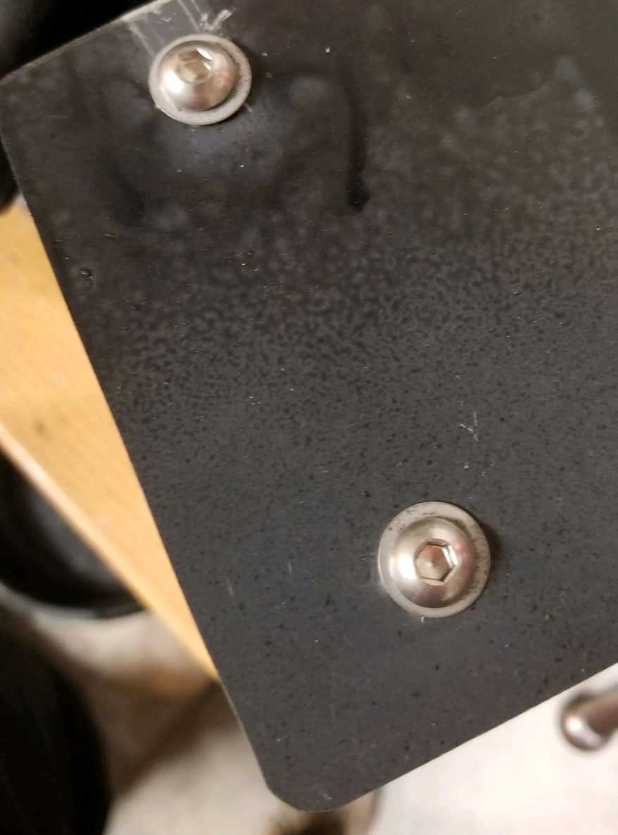 TOP VIEW BELOW. These bolts stick out underneath and you'll see how they're used for mounting this to the dash.  |
|
|
|
|
| The final steps involved making these two angle braces, which were then epoxied onto the inside walls of the pod shell. |
|
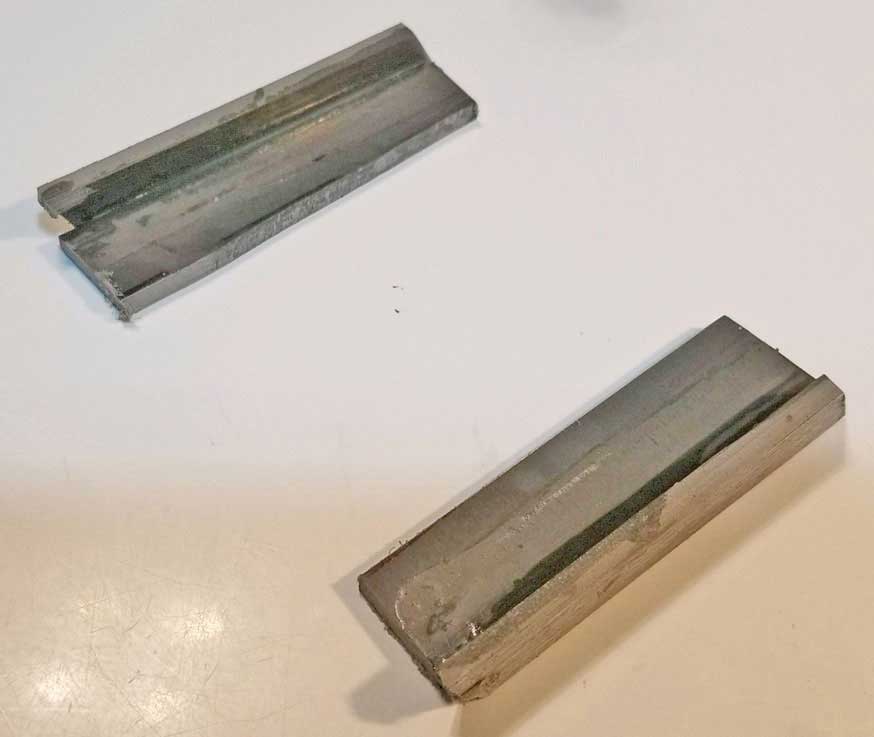 
Then the bottom speaker grill piece was mounted onto those angle braces using four counter-sunk screws. 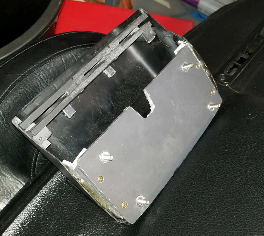 I cut a notch using my bench grinder into the bottom piece to allow room for gauge wires and a vacuum hose for the boost gauge.  As mentioned before, I had changed my mind about using these WING NUTS on the bottom after I found they tended to vibrate loose too easily when driving. The final solution after I got rid of the wing nuts was some simple NYLON LOCK NUTS, which would never vibrate loose. 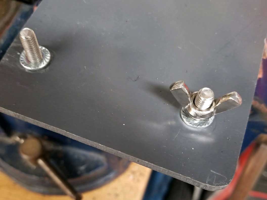
|
|
|
|
|
| Final Test Fitting on a Spare Dash. |
|
   |
|
|
I considered buying some black vinyl material with a faux-leather texture to wrap around this pod. In the end I didn't try that, but if you want to try it, here's a good vinyl that reportedly works very well for such a dash project. Self-Adhesive Vinyl Fabric Faux Leather 56" Wide by the Yard. https://www.ebay.com/itm/195990050265?var=495854373142 |
|
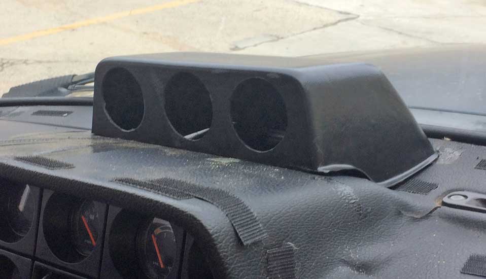
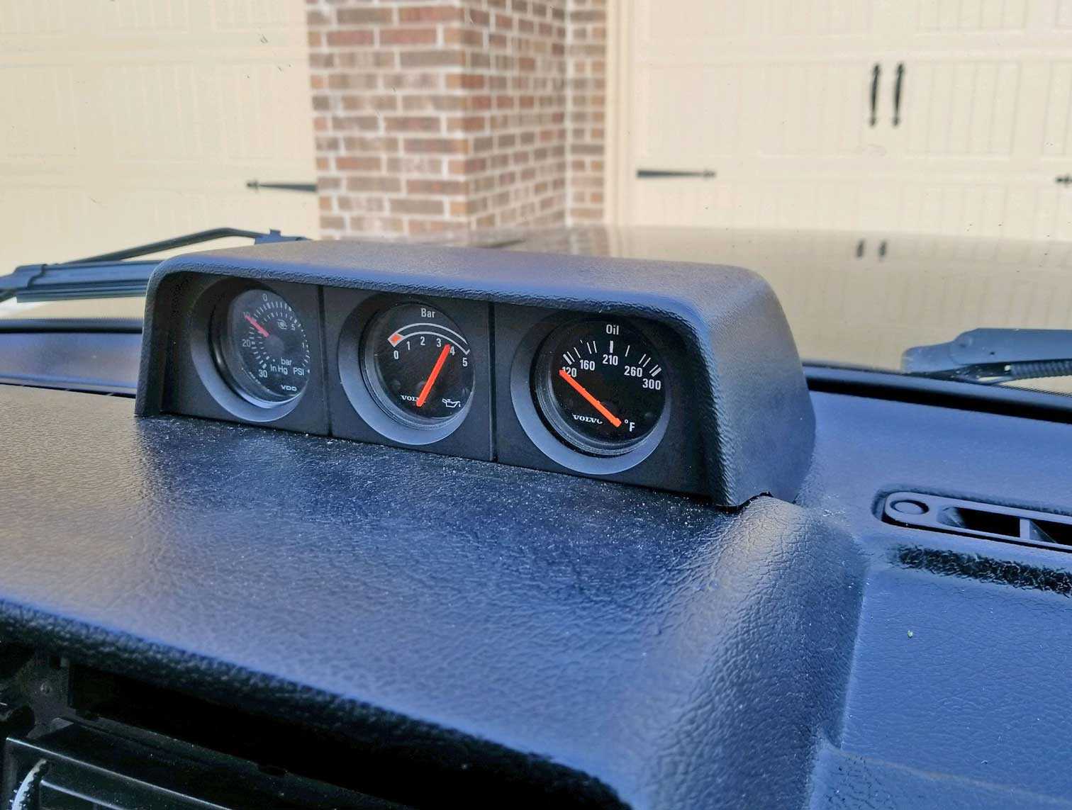
| Here's the fully assembled gauge pod after installation in my 242. It's hard to see, but this pod is pretty close to the windshield at the upper back of the pod. |
|
|
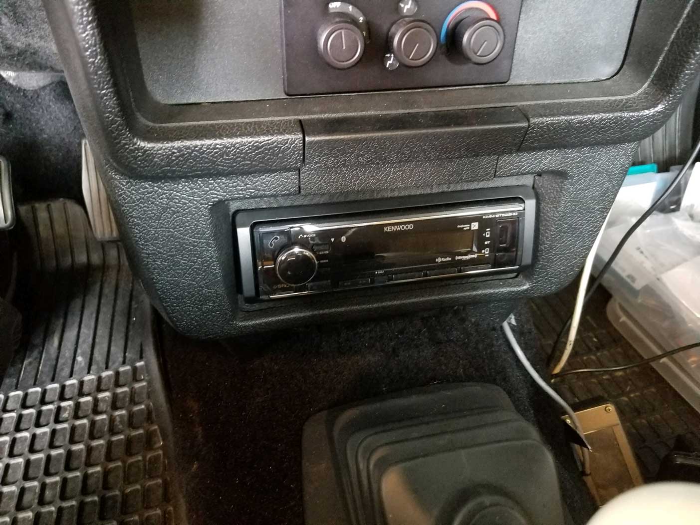
This new pod gave me the opportunity to move my radio up to my preferred top position, which I couldn't have done before while keeping my gauges. I hated having the radio down low where it was such a strain to see it when driving.
|
|
Here
are pics below of my dash before and after moving the radio up. 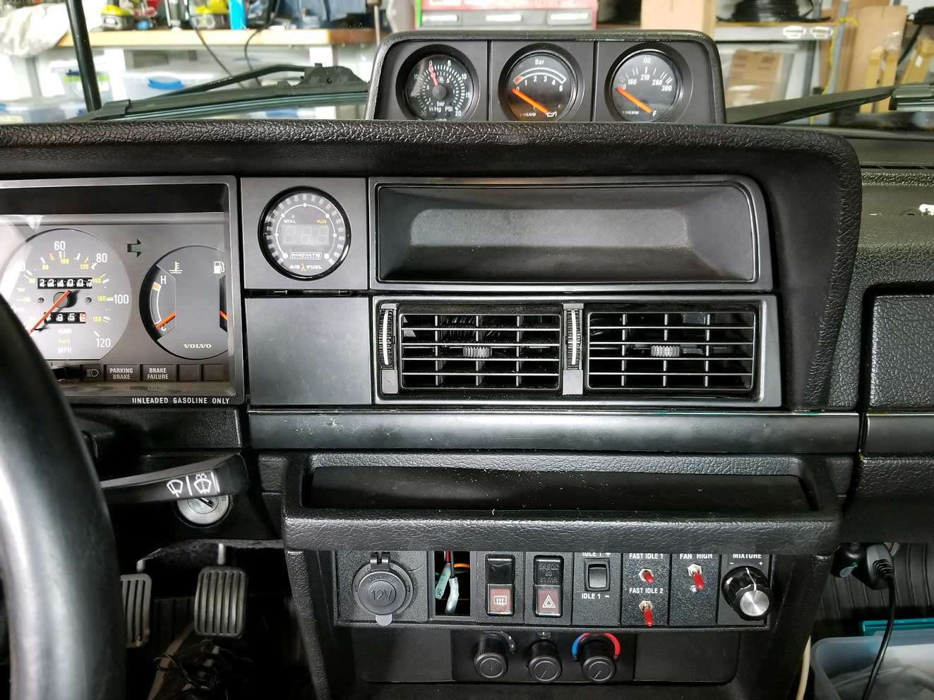 Being able to actually see the radio when driving is so much nicer now. 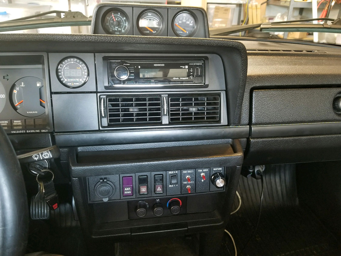 |


 alternators are known for poor voltage.")


