|
2 4 0 T U R B O . C O M D A V E ' S V O L V O P A G E
|
||||||||||||||||||||||||||||||||||||||||||||||||||


 alternators are known for poor voltage.")


| WATTS TO AMPS CALCULATOR If you know the Watt rating of a fan, you can use that to calculate Amperage. https://www.inchcalculator.com/watts-to-amps-calculator/ |
|
2 4 0 T U R B O . C O M D A V E ' S V O L V O P A G E
|
||||||||||||||||||||||||||||||||||||||||||||||||||
| WATTS TO AMPS CALCULATOR If you know the Watt rating of a fan, you can use that to calculate Amperage. https://www.inchcalculator.com/watts-to-amps-calculator/ |
| Brushless Fans (Page 2) |
| --- BRUSHLESS FANS ARE PRETTY NEW STUFF --- When I first started paying attention to these, there was a STEEP NEW LEARNING CURVE for me. |
| In 2023 I began looking closer at brushless fans after I saw some videos and test data which suggested some BRUSHLESS fans
can significantly out-perform old-school BRUSHED fans, offering higher speeds, more airflow, and all while often using LESS AMPERAGE. My Volvo 240 has a high-performance alternator powering very cold 32ºF Air Conditioning
that works awesome even in 100ºF plus temps. And it has a big custom
radiator, which can handle all that in any climate, even going up
endless grades. A big cooling fan has always been a priority. The previous fan in my car was a BIG Lincoln Mark VIII fan, which is a brushed fan, which I tested (14.5v) at 3900 CFM in free air and 3200 CFM installed with a radiator, intercooler and AC condenser. The Lincoln Mark VIII was fine at handling all my cooling needs as long as I was using a good controller with a soft start. If you're not using a soft start controller with a big brushed fan, the huge amperage spikes can be really bad. Brushless fans have an advantage on this subject, since they don't have an amperage spike problem. They're always smoothly controlled. After I transitioned to a comparably sized brushless fan (Jeep JK fan), I found that BRUSHLESS fans can be so much BETTER. There will be lots of performance test data in this page, but there's one very interesting thing I have found during testing that I wasn't aware of. Brushless fans often become MORE efficient at HIGHER voltage levels. I began testing brushless fans at 12.7v static battery levels and then later at 14.5v with the engine running. In many tests I found a brushless fan spins faster and pulls more airflow with LESS AMPERAGE DRAW when used at HIGHER voltage levels.
|
| -- NOTABLE BRUSHLESS FANS -- |
| I'm interested in
learning about any other brushless fans that you may have found useful for projects, especially if there's a chance they can be made to work in an OLDER VOLVO.
For convenience sake, I like to identify any decent fans which can be made to fit a 240 or 740 radiator width without a lot of trouble. Lots of info in this page comes from others who have contributions. If you come across any useful fans and can offer useful info, please let me know. CONTACT |
||||||||||||||||||||||||||||||||||||||||||||||||||||||||||||||||||||||||||||||||||||||||||||||||||||||||||||||||||||||||||||||||||||||||||||||||||||||||||||||||||||||||||||||||||||||||||||||||||||||||||||||||||||||||||||||||||||||||||||||||||||||||||||||||||||||||||||||||||||||||||||||||||||||||||||||||||||||||||||||||||||||||||||||||||||||||||||||||||||||||||||||||||||||||||||||||||||||
| DELTA PAG BRUSHLESS FANS If you happen to notice that DELTA PAG is the FIRST FAN listed in this page, it's not a coincidence. After you read more, I think you'll agree that these fans should be near the top. 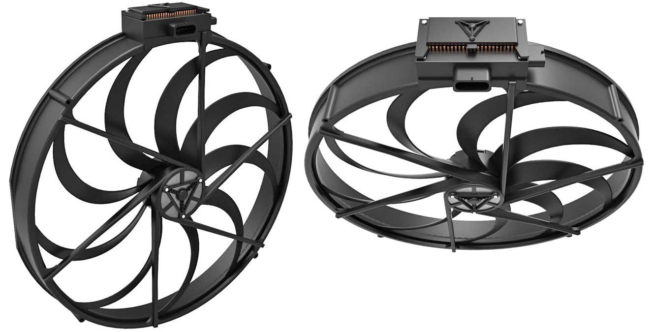 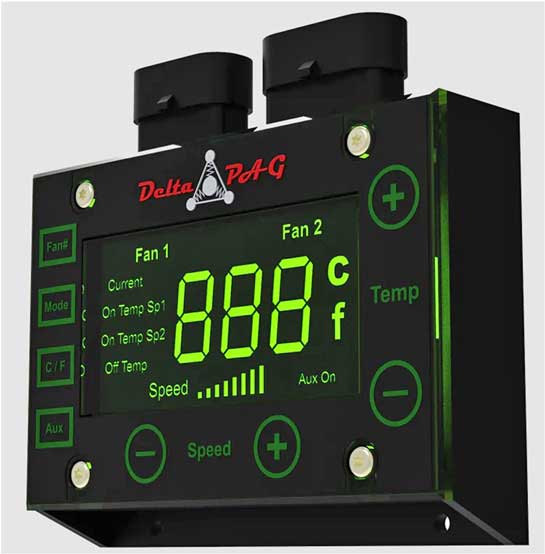 Delta PAG https://deltapag.com offers 12 inch, 14 inch, 16 inch and 18 inch fans, and all are available as either pushers or pullers. Delta PAG also offers a digital controller with digital displays for programming the temp-speeds.  From what I have gathered, all Delta Pag brushless fans are designed to use the Delta Pag controller. They don't offer any alternate controller information and so far I have not seen any published PWM frequency or POLARITY requirements for their fans. When I first began this page, I found a few videos showing Delta PAG fans performing extremely well. In 2015 Delta PAG introduced a 16 inch brushless fan which is shown in the first video below.
Delta PAG rates their 16 inch brushless fan at 3200 CFM, using about 22 amps at 13 volts. Maximum RPM is about 2900. They rate all their fans using a radiator in front of the fan (with LOAD). Putting a radiator in front of any fan creates a restriction and reduces the air flow. If you instead test a fan in free-air (nothing in front of the fan), the CFM results will be much higher. A free-air test is a valid test too, but not as realistic when you find out how much a moderate restriction like a radiator reduces airflow. Higher Air-Flow due to Center Hub Design Delta PAG also states that they're able to achieve 25% more airflow than other brushless fan designs because of their unique motor design, which has a much smaller center hub (about 3.4 inches diameter for the 16 inch fan). With that smaller center hub, an impressive improvement is made. Pretty much all other brushless fan motors have huge center hubs in comparison, because other brushless fans contain speed control electronics inside the hub. Delta PAG has made their speed control module a separate part, which is mounted nearby and out of the way from airflow. It seems logical that this can offer a significant improvement to airflow. In the Spal section below, Spal's most powerful 16 inch brushless fan is rated at 2430 CFM at 42 amps (with a 7 inch diameter center hub). So it seems there's validity to Delta PAG's improved air flow claims. A mechanical drawing of their 16 inch fan is shown in their web site. For a Delta PAG fan, the 16 inch measurement refers to the overall width of the fan assembly at the outside (16.00 inches). So this means the actual fan blade diameter is actually a bit smaller, closer to about 15 inches. This type of advertised measurement is pretty universal with most fan manufacturers, so keep this in mind when comparing fans by size. If you need more precise measurements, most fan manufacturers have dimension drawings you can see. Power Consumption vs CFM I've seen comments from Derale about expected fan consumption (they sell fans too). Derale says that you can generally expect about 100 CFM for each AMP that a high output fan uses. Example: A 3000 CFM fan might use 30 amps. If that's accurate, then the people at Delta PAG didn't follow it. They've achieved a far greater airflow to amps ratio. Do the math: The 16 inch fan above makes 3200 CFM from 22 amps? Pretty good. Using less power is good for your charging system. 18 inch Delta PAG Fan The larger Delta PAG 18 inch fan was introduced more recently. It's rated by Delta PAG at 4100 CFM at 13 volts, using only 26 amps. Another awesome airflow achievement using minimal current. Maximum RPM is about 2900. Again their CFM rating is assuming there's a radiator installed in front on the fan. Some manufacturers don't rate their fans that way. Putting a radiator (and maybe a condensor and intercooler) in front of a fan creates an air restriction and REDUCES flow. This reduction is much more than I would have expected before I did some testing for myself. Any fan will be affected, but a very strong fan like this one will do a better job of overcoming a restriction than a weak fan.
Testing CFM air flow using an ANEMOMETER is how I have compared fans that I have tested. It's not scientifically perfect, but it can be fairly consistent as long as you use accurate fan area calculations. I'm always curious as to what methods and calculations other people are using in their own anemometer tests. I was especially curious about that 5100 CFM test in the above Delta PAG video. Delta PAG rates that 18 inch fan at 4100 CFM and their ratings are made WITH the restriction of a radiator. So if a Free-Air Test is that much higher, it appears we need to accept that a radiator restriction can reduce air flow by 20% or more (5100 to 4100 CFM in this case). When I first saw this, it seemed like a lot of airflow drop to me. Later I was able to do some of my own FREE AIR testing and with some fans, including INSTALLED testing with my radiator, AC condenser and intercooler. I did some tests with my old brushed Mark VIII fan and also with the big Jeep JK brushless fan I installed (seen here). I have confirmed that a big drop in airflow is definite going to happen when a radiator or other restriction is put in front of the fan. It's pretty significant! Here's a short video showing this 18 inch fan on a radiator blowing 4200 CFM. https://www.youtube.com/shorts/VR6URYXx4tA 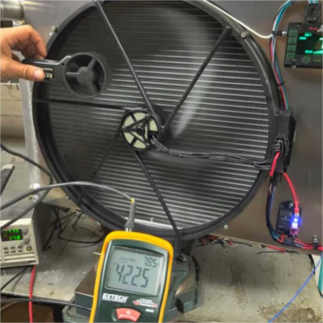 -- DIMENSIONS -- With respect to advertised fan size, I will point out this 18 inch Delta PAG fan (SEE BELOW IMAGE) doesn't actually have 18 inch fan blades. This fan is called an 18 inch fan because it measures 18.11 inches at the outside of the shroud assembly. So the actual fan blade diameter is probably around 17 inches or so. I'm not saying this is bad or if this fan might disappoint you. This fan out-performs nearly all other fans from other manufacturers. I only point out the actual blade size because I don't think enough focus on actual fan dimensions when comparing fans across different manufacturers. DELTA PAG 18 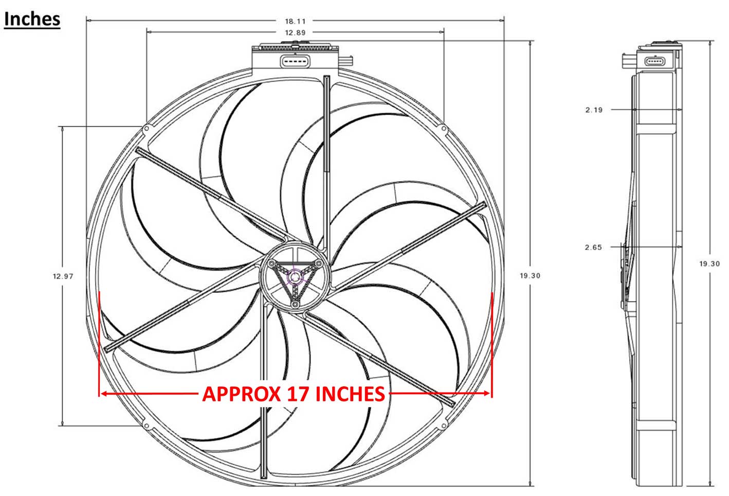 DELTA PAG 16  Also I think some people on the internet are incorrectly using ACTUAL FAN BLADE SIZES when calculating their own CFM tests. Consistency matters. Accurate anemometer tests require accurate fan area measurements to be used. I saw one test of THIS SAME 18 inch fan above using an anemometer, where the tester ignorantly used the FAN AREA for an 18 inch fan (instead of the correct 17 inches) and then he ALSO failed to deduct the area of the center hub. Then he published a finding of 3900-4000 CFM. A test like this is probably NOT very accurate. Entering an exaggerated cubic foot value into an anemometer always results in an exaggerated CFM reading. Ultimately, I think you can use anemometer CFM tests as an estimation tool, but true comparisons are probably not possible unless the fans are tested with the same anemometer or same method, and of course a must is having consistent fan area calculations. If some CFM tests are inaccurate, How far off could they be? Using the above example, if someone uses the area calculation for an 18 inch fan when they actually have a 17 inch fan, it can result in an exaggeration of about 6%, or as much as 250 CFM. And if that person fails to deduct the area for the center hub, this will result in error too. Delta-PAG fans have a really small center hub, so it would be a smaller error in this case. About 3% or about 120 CFM. This kind of error with other brushless fans with much larger center hubs can result in errors of 6% to 8%. Are there any draw-backs to a Delta PAG fan? I have not found any draw-backs with these fans (although I don't own one). I certainly would consider owning one. I think these are really great fans. When I first began looking at these fans, I was particularly interested in how their digital speed controller was able to trigger a separate fan speed for when your AC was ON, but it could only offer full-speed for that option. As of December 2023 this has changed. Their controllers now offer the ability to control an AUX SPEED, so you now now have some variable speed options for when AC is ON. This is a nice option if AC is important to you. I'm one who likes to choose a middle speed (around 50% to 70%) for when the AC is on. Using FULL-SPEED for AC is rarely needed if you have a really powerful fan. If you're interested in a LOT more information about these particular fans (not posted in other places), there's a long-winded technical discussion in this linked Corvette C7 forum below. This link below takes you to page 3, where the serious discussion begins. Some good info. tbssowners.com/threads/c7-pwm-brushless/page-3 I refer to Fast Monty's Garage a few times in this page. He's been doing some very useful fan testing. One test below shows a Delta PAG 14 inch fan he tested.. Delta PAG 14 inch Brushless Test. CFM, Noise, and Amp Draw! https://www.youtube.com/watch?v=cOSS5s65ngk USING A DELTA PAG FAN IN A VOLVO? This is absolutely possible, however I know that most old Volvo owners are more inclined to look for the CHEAP solution. This is not the CHEAP solution. But it's a very elegant one. Certainly the Delta PAG 16 inch fan can be used with a stock size Volvo 240 radiator. Stock Volvo 240 radiator dimensions. Volvo 240 Radiator Overall: 17.5 inches high, 22 inches wide, 2 inches deep.  An 18 inch fan could fit a LARGER than stock radiator. You would need to come up with a fan shroud, or have Delta PAG make a shroud to your specs, which they will do if you ask. Some photos of those are BELOW. If you decide to pursue a Delta PAG in a Volvo, please let me know how it goes. I'd like to post more info about these fans here. If you're curious what a Delta PAG 16 inch fan would look like with a custom shroud (this one was made by Delta PAG for the customer) for a radiator similar in size to the Volvo 240 radiator, have a look at this image below. This was posted in Facebook by Delta PAG. The cost was reportedly $780 including the fan, controller and the custom shroud. facebook.com/photo.php?fbid=914689603997963  Delta PAG 18 While this bigger 18 inch fan below will not really fit on a STOCK sized 240 radiator, these images below show a Delta PAG 18 inch fan with custom shroud, which was created for a 1967 Corvette from this forum link: corvetteforum.com/forums/delta-pag-18  The customer painted the shroud black.  SPAL BRUSHLESS FANS Spal Plus 16 brushless fan shown below.  Current Spal aftermarket brushless fans use 100 Hz PWM and have POSATIVE polarity. The Spal USA site https://www.spalusa.com has some catalog info showing BRUSHED fans, but the USA site does not show a listing of their brushless fans. You can see BRUSHLESS fans in the Italian page: https://www.spalautomotive.it/brushless There is also a brushless catalog PDF at: https://www.spalautomotive.com/documents/20182/94723/brushless_catalogue.pdf/ I believe Spal first introduced their line of aftermarket brushless fans in 2014 with sizes up to 16 inches. These were called the "NUOVA" series. An announcement believed to have been dated 2014 is below:
SPAL THEN INVERTED THE PWM SIGNAL RAMPS ON THEIR AFTERMARKET FANS I don't know what year this change was made. I have been told by others that Spal discovered that they were selling lots of their "smart" sensors needed to run these new fans, but instead of selling a lot of new (expensive) aftermarket fans, they discovered people were using the sensors for less expensive OEM fans from C7 Corvettes (2014+) and Gen6 Camaros (2016+), which were all made by Spal for GM. So then Spal decided to discontinue the "smart" sensors which worked with Corvette and Camaro fans and they created a new line of sensors which CHANGED the PWM duty cycle ramps. And then they changed all their new aftermarket fans to match the new "smart" sensors. I know this may be confusing. The new aftermarket fan series was then called the "PLUS" series and the old NUOVA series was then eliminated. From that point forward all new Spal "smart" sensors would only work with their second generation PLUS series fans, and OEM (Spal) Corvette and Camaro fan users were mostly tossed out in the cold (for a little while). SPAL "SMART" SENSORS 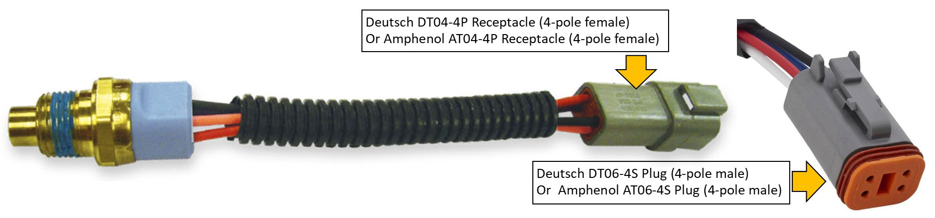 3/8 NPT threaded end. 4-pole electrical connector: Deutsch DT04-4P Receptacle (female). Mating plug you'll need may be 4-pole connector: Deutsch DT06-4S Plug (male) or Amphenol AT06-4S Plug (male). More more information about these Deutsch or Amphenol connectors, go here: https://www.240turbo.com/crimps.html#deutsch 1st Gen Spal aftermarket brushless fans have NEGATIVE polarity. PWM duty cycle set for LOW speed = 85%. HIGH speed = 15%. SBL-TS01: Turn on 140F - Max at 165F. SBL-TS02: Turn on 165F - Max at 185F. SBL-TS03: Turn on 190F - Max at 215F. If you still need one of these, CLICK HERE for Vintage Air sensors. SUMMARY of the CHANGES from 1st Gen to 2nd Gen Sensors: Spal NUOVA series (1st generation aftermarket fans): With these NEGATIVE POLARITY fans, the speed DECREASES as the PWM duty cycle signal increases. This is an INVERTED speed ramp. OEM C7 Corvette and Gen6 Camaro brushless fans (made by Spal) also use this type of PWM signal. Spal PLUS series (second generation aftermarket fans): With these fans, speed INCREASES as the PWM duty cycle signal increases. SECOND GENERATION "SMART" SENSORS (Available for current Spal PLUS series fans) Current Spal aftermarket brushless fans have POSATIVE polarity. PWM duty cycle ramp set for LOW speed = 15%. HIGH speed = 85%. SBL-TS-165P: Turn on 140F - Max at 165F. SBL-TS-185P: Turn on 165F - Max at 185F. SBL-TS-195P: Turn on 175F - Max at 195F. SBL-TS-215P: Turn on 190F - Max at 215F. (Multiple fans can be run using ONE sensor) NOTE: SPAL FANS REQUIRE A 100 Hz PWM FREQUENCY. 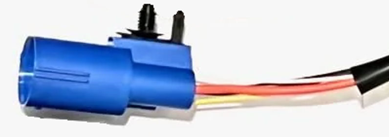 The connectors on these Spal fans are this Yazaki 4-pole MALE plug above. The matching FEMALE connector BELOW can be found here: Spal PN 30130628 in Amazon: https://www.amazon.com/dp/B07CTDGNGT. FYI, this is the same mating plug needed for the Camaro fan and also the Jeep fan further below in this page. This kit comes with several different sizes of terminals for wire size up to 8 gauge. 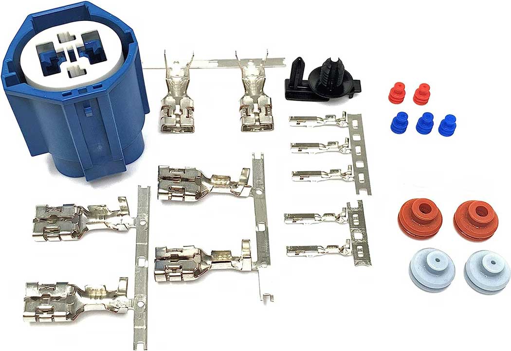 Can Spal "Smart" Sensors be used for OTHER Brushless Fans? Yes, for some. Spal fans require a controller (or it can be a sensor) which uses a 100 Hz PWM frequency. Some other fans use that same frequency. If you find a fan which uses 100 Hz, that fan must also use a PWM duty cycle ramp like that used by the Spal Plus series, one that powers the fan at low speed when the PWM duty cycle is low (This means the fan has Positive Polarity). If a fan runs and low speed when the duty cycle is high, that fan would be Negative Polarity. There are work-arounds if you need to adapt a fan that doesn't match the polarity of you controller. You can use a device which can invert or even completely change a PWM frequency (shown further down in this page). Keep in mind that some fans from different manufacturers may share the same frequency, but the duty cycle ramp may be INVERTED. For more information on how this can affect PWM signals or how PWM signals work, CLICK HERE for PWM Info section. If you have a need to INVERT the polarity of a PWM signal or alter the frequency, it can be done EASILY. There are some devices SHOWN HERE which can do this for you. WIRING A SPAL PLUS FAN to a SMART SENSOR Here's a Spal diagram below showing how one of the above Spal sensors is wired to a Spal Plus aftermarket brushless fan. While these sensors will work, there are plenty of other options to control a Spal fan if you decide you want something better. Note that when wiring a brushless fan this like, it always has the power and ground cables going directly to the battery (or the ground *could* be connected to a good chassis ground). The fan speed/temperature control for this type of fan is regulated through the PWM signal wire. 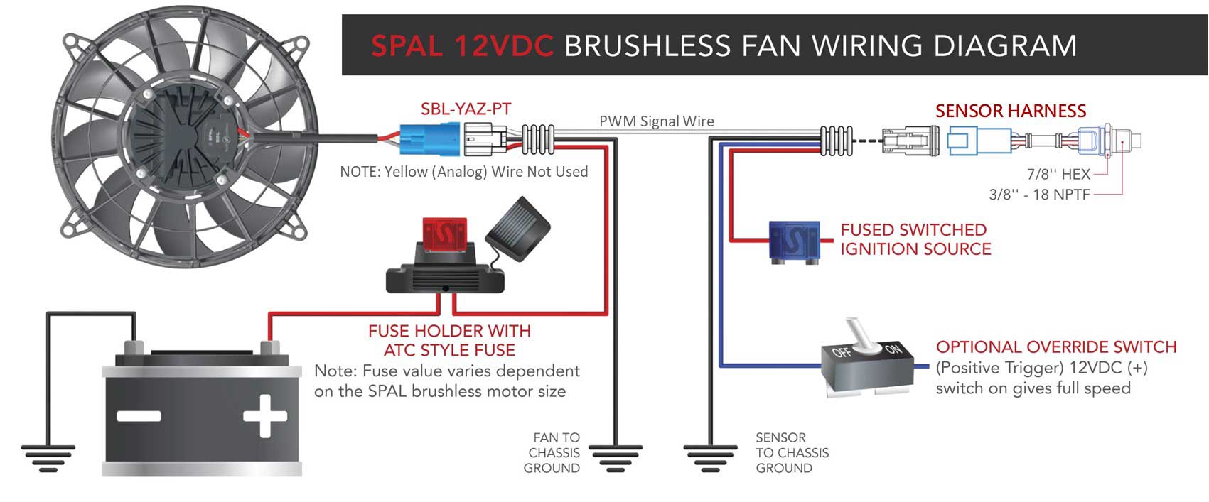 Here are my personal feelings about using a "smart" sensor like this to regulate temp/speed: I don't really care for it. If forces you to choose one temperature range and live with it. It allows no custom adjustments later, so hopefully it's just right for your car as is. Changing to a different range sensor is really expensive. Check the prices of those. A Spal sensor can cost several hundred dollars. I guess the benefit of a simple sensor is simplicity. Also if you have AC and if you want the fan to come on at a higher speed with the AC, your only choice is to wire it so the AC activates the FULL SPEED override. Maybe some people are OK with the fan running full speed when your AC is on. That won't be too as much of a problem if the fan is smaller, but when using a big, high-output fan, I prefer to be able to choose a custom speed for the AC (such as 50%, 70%, etc). Ok, I know you can't ALWAYS have everything you want, but going brushless is more expensive, so I would like to get more satisfaction for my money if I can. Keep in mind that full speed with a big high-output brushless fan can move a LOT MORE AIR. It might be way more than you need and it might use more way amps than you want. Learning how to control a SPAL Brushless Fan from scratch. https://www.youtube.com/watch?v=1kRsGcjU1Ck For those who might buy a fan like this and want to know about to testing tools, a simple PWM signal generator can come in handy. CLICK HERE: Testing a Brushless Fan CLICK HERE: Activating a Brushless Fan   Should a FUSE be used with a Brushless Fan? A fuse is not required, but it adds a level of safety. A BIG fuse is recommended. And make certain you buy a high quality fuse holder, not a cheap no-name one. This is a Maxi Fuse holder below from Blue Sea Systems with a 50 amp fuse. I used it in my car and it's placed between the battery positive and the fan. I bought one of these after a cheaply made Bussman Maxi Fuse holder melted the metal contacts and failed badly. Click HERE for more details about th Blue Sea Systems fuse.  Should a RELAY be used with a Brushless Fan? According to Spal: “Relays are used with BRUSHED fans, and NOT used with BRUSHLESS fans. As brushless fans are growing in popularity, we have had a few customers try to add a relay to a brushless system when a relay isn’t required. We don’t need a relay with brushless fans because they always do a soft start. In a brushless fan system, the fan is connected to constant power – directly to the battery. When the brushless fan receives the command signal to run, it makes a connection internal to the motor and runs. When the command signal goes away, the brushless fans enter quiescent current (sleep) mode.” SOURCE: https://www.streetmusclemag.com/tech-stories/fuel-cooling-ignition-tech/the-7-best-practices-for-wiring-automotive-fans-with-spal-usa/. Spal catalog info sometimes makes references to a fan being a puller or pusher. As you'll see in the below image for some Spal 16 inch "PULLER" fans, the airflow is pulled IN from the side with the center fan hub then OUT to the side with the fan motor. This type of fan is made to be inserted and mounted into a shroud using the outer flange on the fan grill edges and with the fan motor facing to the REAR and the fan center hub facing the front, or facing the rear of the radiator.  From info I found in the Spal fan engineering catalog, the faster 2430 CFM fan above (which uses a 500 watt motor) will use about 30-33 amps at full speed. The slower 2053 CFM fan (with a 300 watt motor) will used about 20 amps. These results are probably better than the performance numbers for the similar Spal BRUSHED fans. More notes about PUSHER or PULLER fan designations. Most fans are designed to run only ONE DIRECTION. Many are designated as either pushers or pullers. Most fan blades (especially curved ones) are designed to be most efficient in only one direction. In most cases a PUSHER fan will be on the FRONT of a radiator (sometimes the front of an AC condenser). In most cases a PULLER fan will be BEHIND a radiator. The most efficient way to move air through a radiator is by using a PULLER fan with a fan shroud. What is FLUSH MOUNT? If you look closer at any of the aftermarket Spal fans, you'll find that some are call Flush Mount. This means that the fan is designed to be mounted FLUSH on a fan shroud surface as shown below, where most of the fan is on the inside of the shroud.  SOME 12 VOLT SPAL BRUSHLESS FAN INFO LISTED BELOW. Most are PULLERS.
SPAL big 18 inch fans. Spal shows a couple 18 inch 12 VOLT brushless PULLER fans in their catalog info: https://www.spalautomotive.it/brushless. The motor on this fan below is 850 watts. This fan is listed in the table above. PN VA164-ABL806HT/R-116A. This is similar to the fan used in the 18 inch Camaro SS fan. It seems to be hard to find this large 18 inch fan for sale, but as of 2025 Spal has been actively showing it at SEMA, so it will probably become easier to find eventually. So far that I know of, a few of these 18 inch fans have only been found on occasion on eBay. If you search, pay attention to the exact PN, because some with slightly different numbers are 24 volt. The eBay fans were offered as "brand new" fans, which were originally purchased by an undisclosed vehicle manufacturer for testing, then later unloaded on eBay. Here it is at SEMA in November 2025. They call it a 19 inch fan in this video, but if you measure the blades, it's 18. https://www.youtube.com/watch?v=YM18bxMemXo   This is a PULLER fan. Air will flow IN from the side with the center fan hub then OUT to the side with the fan motor. So looking at the image above left showing a view of the fan motor, this side will face AWAY from the back of the radiator. The image above right showing the center fan hub will face the radiator. Keep in mind that this center hub protrudes some toward the radiator and past the fan outer mounting surface. That can be seen also in the below drawing from Spal. Spal catalog info sometimes makes reference to a fan being a puller or pusher, but not always. Even airflow direction is not always shown in their fan descriptions and diagrams. As you'll see in the below image for this big Spal 18 inch fan, the airflow is pulled in from the side where fan blade center hub is, and it exits out past the fan motor. So this fan is considered a PULLER.  The above drawing of the 18 inch fan PN VA164-ABL806HT/R-116A comes from a Spal catalog found at: https://www.spalautomotive.com/documents/20182/94723/brushless_catalogue.pdf/ This 800 watt fan (or 850 watt, depending on who you ask) has been studied to a degree. Testing has estimated watt usage as high as 887 at 14.2v. The control programming is not the same as what has been found with the 18 inch Camaro fans. During testing it was found that a PWM setting of BELOW 18% resulted in the fan going into REVERSE and ramping up to full speed REVERSE. This is an intended program function for the vehicle this fan was designed for, although I don't quite know what that function is there for. It has been found this big 18 inch fan used about 62.5 amps at full speed, generating about 5100 CFM (at 13v) or about 5500 CFM (at 14.4v) with a maximum RPM of 2800. Here are a couple short reels of this fan in use in a custom 1966 Corvette built by Kuhnhausen Metal Concepts. https://www.facebook.com/reel/3385442374949138 https://www.facebook.com/reel/1869859017016847 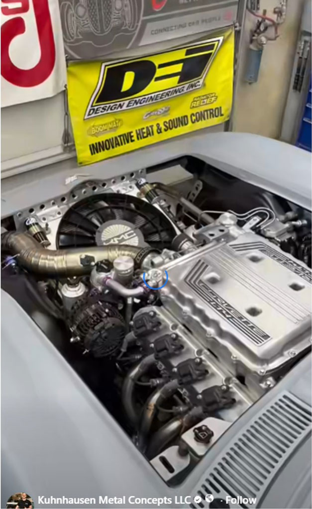 SPAL big 18 inch fan with 1000 Watt Motor. This fan is listed in the table above. Spal catalog info shows this big 18 inch 12 volt fan as PN VA164A-ABL1002HT/R-124A. It has a 1000 watt motor. This is a monster and I think it would be hard to justify such a fan except for in the most extreme uses. One such fan was purchased by someone who sent me his testing results. It was bought with the thought of using it for a custom truck made for overland adventures. Some information about this fan was then sent to me. Some of these fans have only been found on occasion on eBay. If you search, pay attention to the exact PN, because some with slightly different numbers are 24 volt. It is believed this fan uses between 77 and 88 amps at full speed, generating up to 7750 CFM at 3400 RPM. The new owner of one of these fans, who sent me his info, was curious about it and he inquired to SPAL USA for more information. He was given the following: This fan will accept 50 – 500 Hz, however most customers choose 100 or 128Hz. This fan has POSITIVE polarity. WIRES: The large RED and BLACK wires are connected to battery positive and negative. The small GREEN wire is an ignition enable wire. 12V must be applied to the GREEN wire to wake up the fan. The small WHITE wire is the PWM wire. The PWM signal requirements are the same as most of SPAL brushless fans. Once the fan is ACTIVE via 12V on the GREEN wire, a setting of 9% duty cycle to the WHITE wire would leave the fan OFF. In other words, if you only sent power the GREEN wire, the fan will activate and slowly ramp up to full speed. The only way to keep the fan OFF when the GREEN wire is energized is to send 9% duty cycle to the WHITE wire. It's believed this may be considered a "Fail-Safe" which could activate the fan to full speed if at any time the PWM signal was interrupted. Anyway, when tested by the owner, it was found the 9% signal had some tolerance and the fan actually remained off between 7% and 11%. The normal upward speed ramp for the fan then began at 12%, which would bring it to about 25% speed. At 16% duty cycle and higher the fan would begin ramping up in a normal linear fashion, reaching maximum speed at 90% duty cycle. SPAL USA has commented that they do not offer this fan in North America to the aftermarket community, partly because of the high power consumption. There are more reasons (coming up). And they don't offer a publicly available data sheet. This fan was developed specifically for a certain British vehicle manufacturer (later found to be the INEOS GRENADIER). Then SPAL made available an "off the shelf" version of this fan (which is what this owner purchased). It was SPAL's opinion that most of the hot rod community cannot properly wire a fan like this or operate it via a fan controller or ECU. So SPAL decided it would not be worth making it available to the general public, since it would result in a customer support nightmare. BMW version of the 1000 Watt Spal The below Spal 1000 watt 12 volt fan can be found used on eBay with descriptions for 2021-2025 BMW M3 or M4. I noticed a number of these are being offered on eBay without the shroud. This may be because those shrouds were damaged in a collision. If you're patient, one with a shroud may come along (photos below were this fan from a Canadian car). Spal PN is VA162-ABL1000HT/R-124A. BMW part numbers found on this fan are 8666819 and 12866310. If you acquire or test one of these fans, I would like to hear from you. 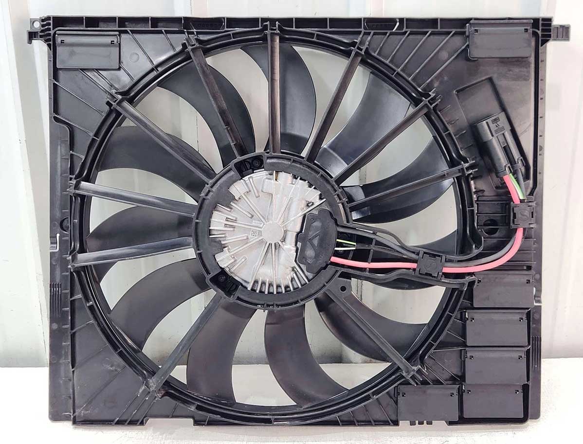 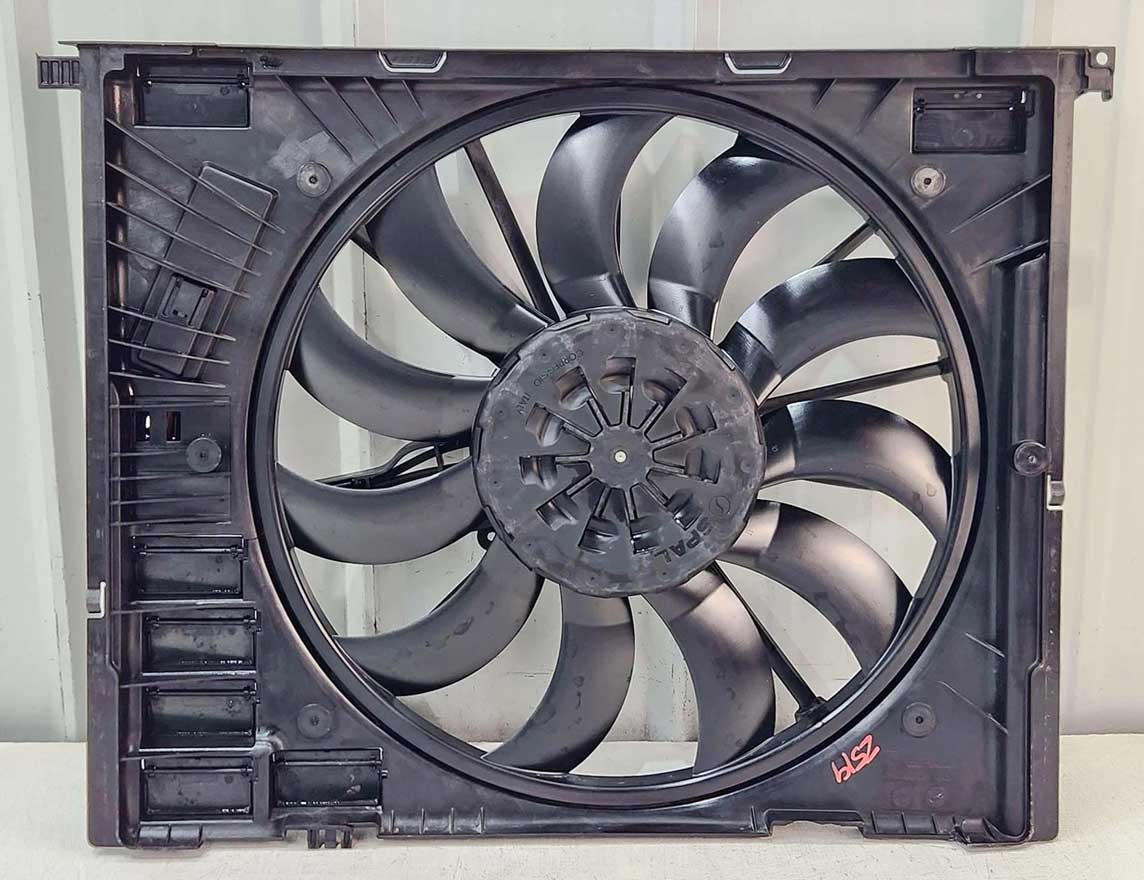 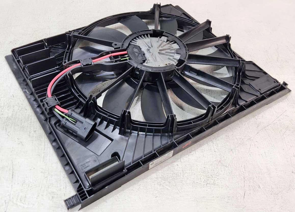 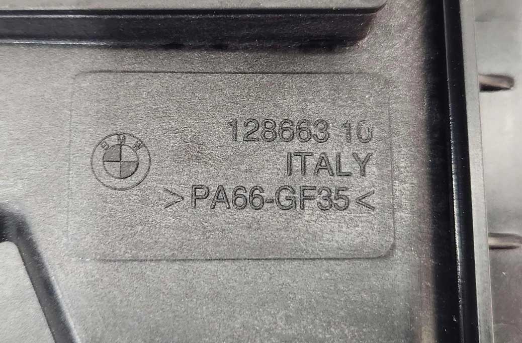 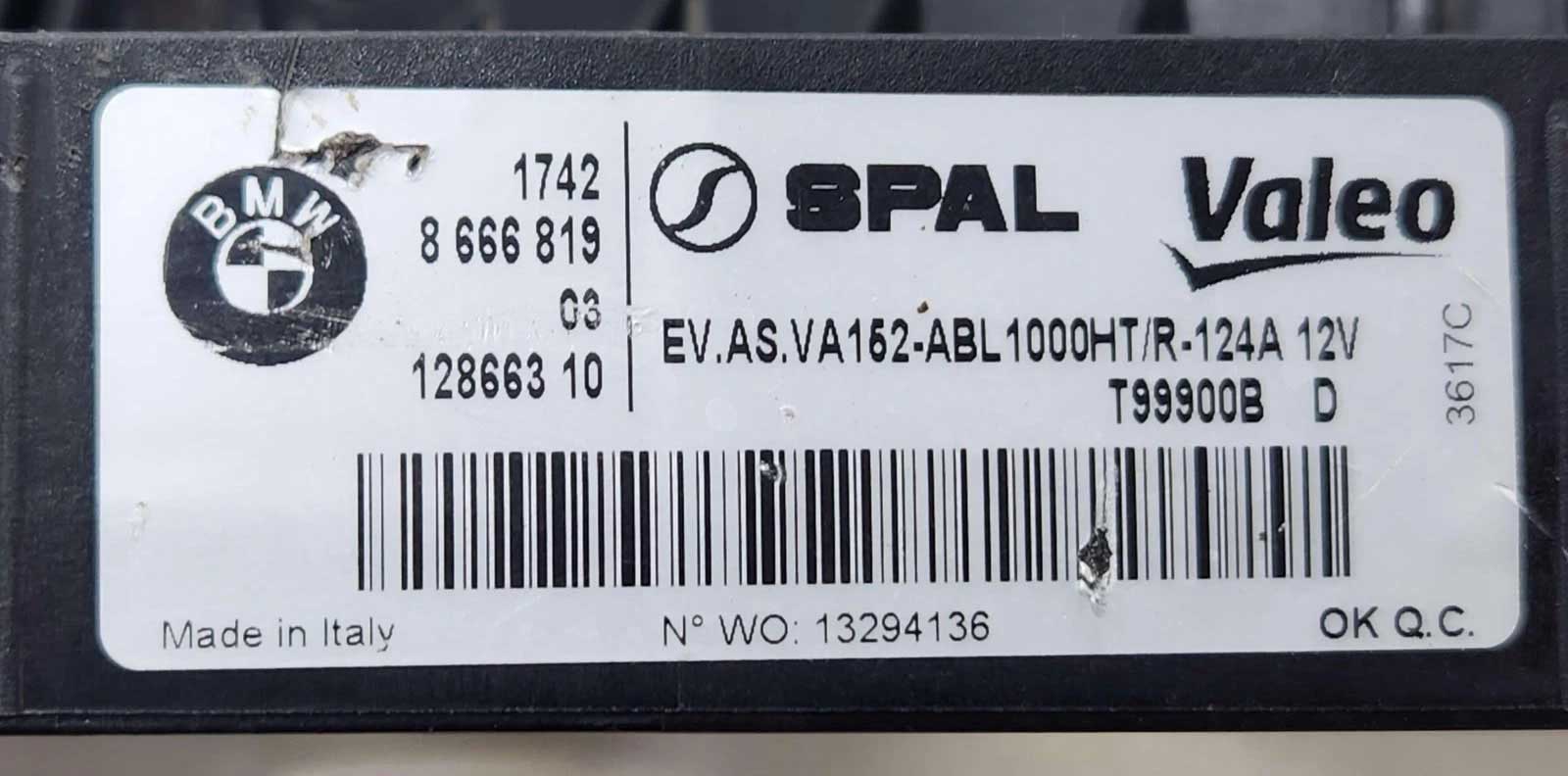 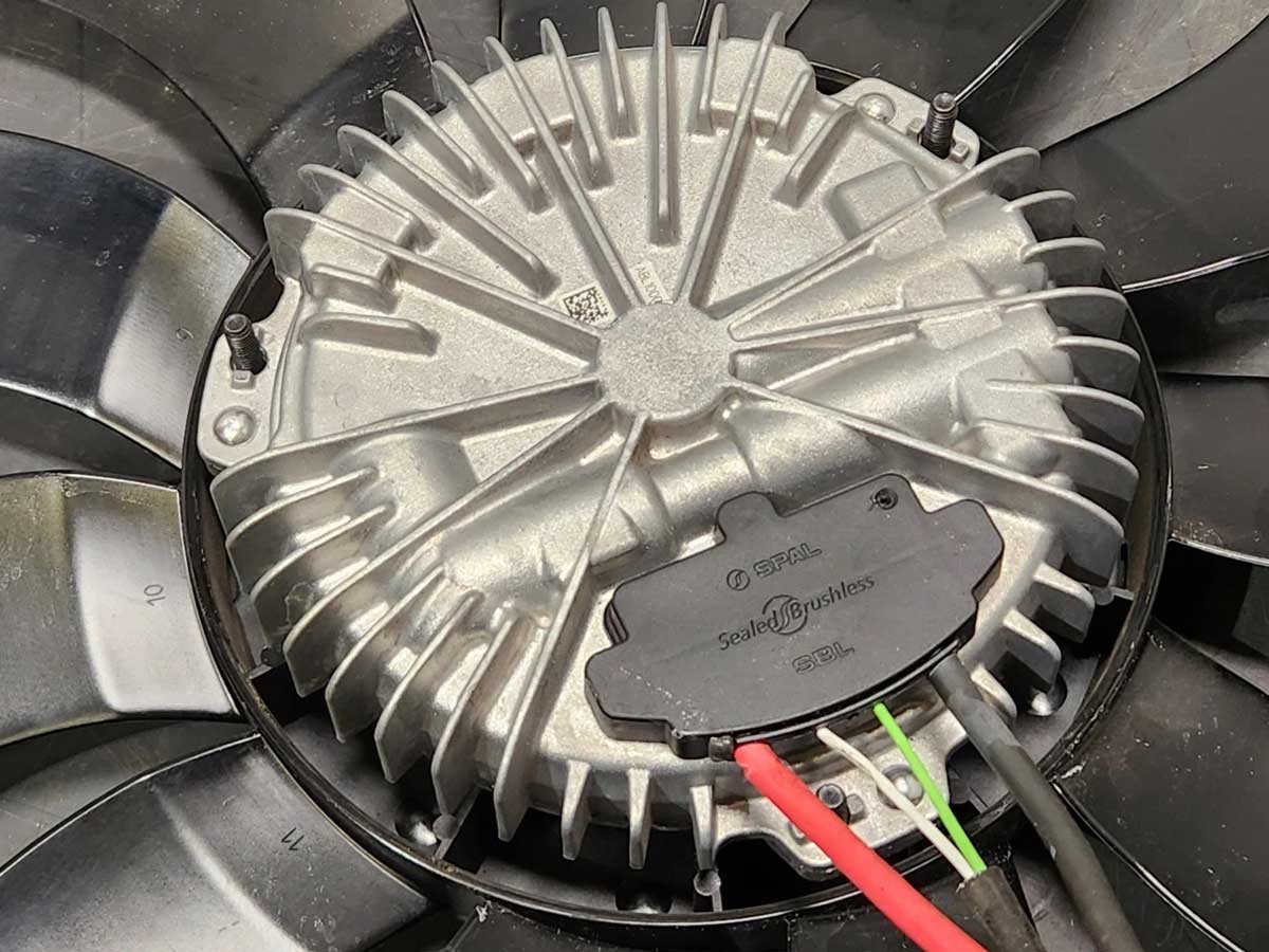 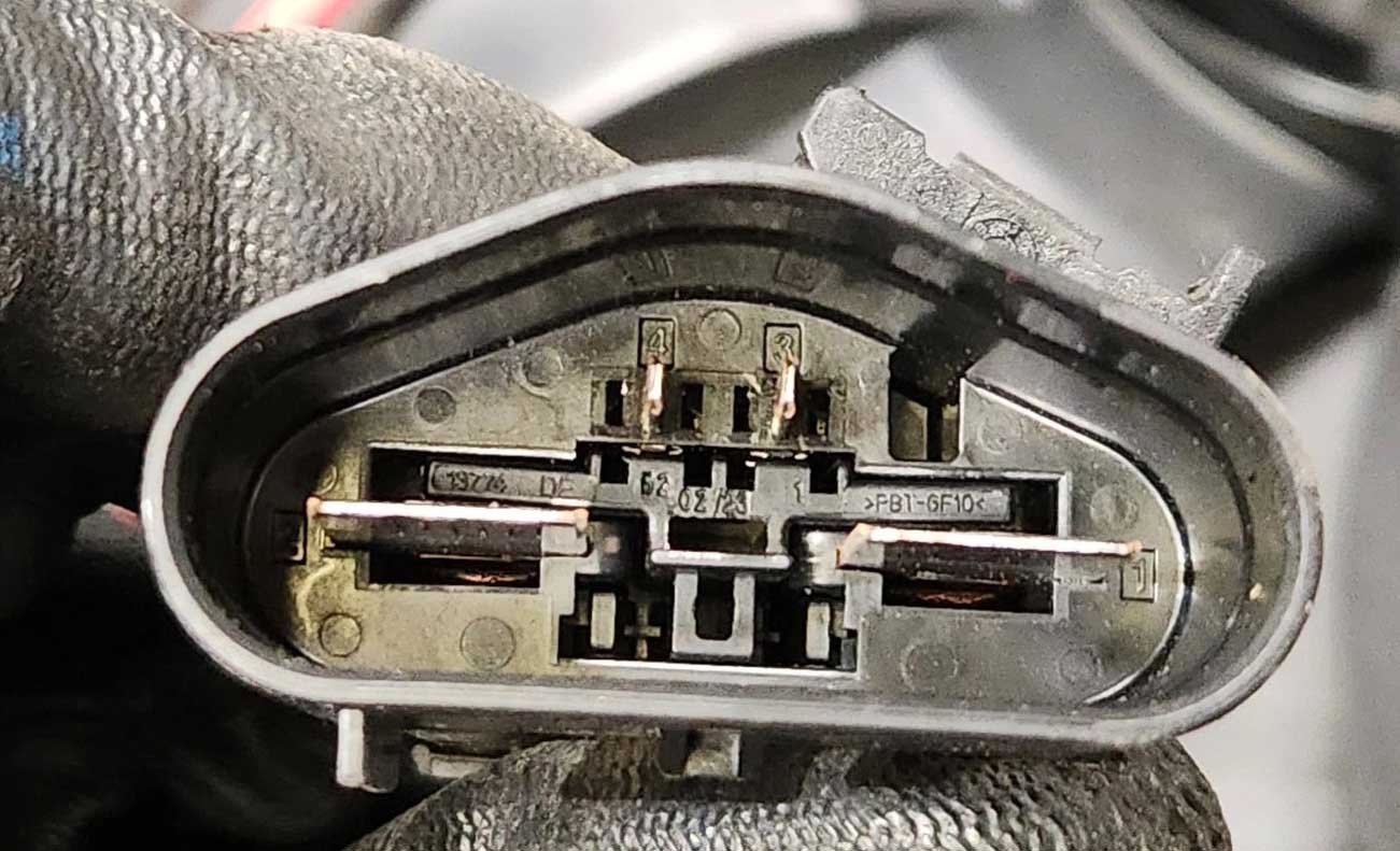 VOLVO XC90 Brushless Fan 18.25" (2003-2014) I'm pretty sure that not all Volvos during these years got BRUSHLESS fans, but it certainly appears most or all XC90s did. Volvo brushless fans use a 128 Hz PWM signal, but they can operate between 100 and 315 Hz. This fan has NEGATIVE polarity, meaning the fan will run slower when up near 90% duty cycle and it'll run full speed when down near 10%.   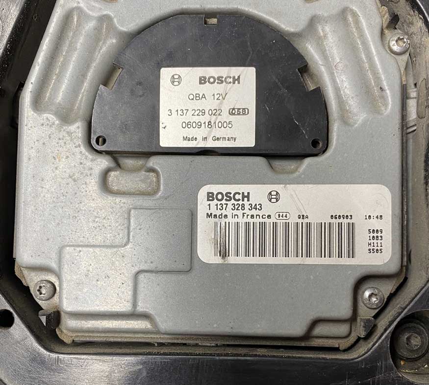
These Volvo fans are made by BOSCH. There is more than one part number out there. Here we have PN 31111543 and PN 30749761. -- DIMENSIONS -- 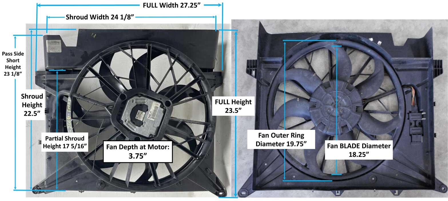 This fan is often described as a "19 inch" fan, although the actual FAN BLADE diameter is 18.25 inches. The internet exaggerates, although 18.25 inches is certainly still a big fan. I have not actually tested this fan. This plug has 3 wires. 1. Large BLACK wire (ground). 2. Large RED wire (+12v). 3. not used. 4. Small VIOLET wire (PWM signal).  I'm not yet familiar with this type or make of connector or a source for finding a mating plug, other than in another Volvo. If anyone identifies or finds a solution for this plug, please let me know. 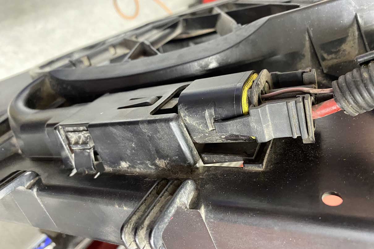 I'm hoping that a good "MIDDLE SIZED" fan might be found between the above 18.25" and this 15.25" fan. If you find such a fan, please share that with me. VOLVO 15.25" S60, V70, XC70 Brushless Fan (2004-2009?) A fan like this may be a good choice to trim and fit into a fan shroud that fits a stock size Volvo radiator. Since I no longer use a stock size radiator in my Volvo, I'm relying on others who might share some info if they try fitting a fan like this. Volvo brushless fans use a 128 Hz PWM signal (can operate between 100 and 315 Hz) and have NEGATIVE polarity. -- DIMENSIONS --  This fan pictured is Volvo PN 8616762 and reportedly came in the following Volvos: 2004-07 S60, V70 2.5T, R T5; 2005-09 S60 2.5T; 2005-06 S80 2.5T; 2005-07 - XC70 Base and Ocean Race. 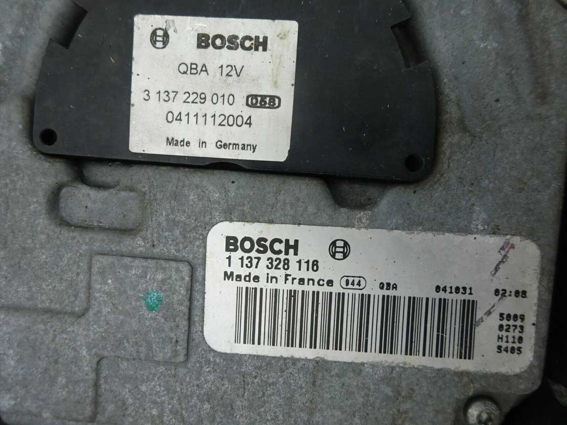  Scott A. bought one of these and he provided the above dimensions for this fan and also some test info below. This fan responds to PWM signals as follows: 1. OFF PWM Signal: 92% to 100%. Fan remains OFF at this setting. Sometimes coming UP from 91%, (thru 92,93,94,95, etc) fan will stay on at MIN speed, but MOSTLY turns off. 100% duty cycle is always off. Going DOWN from 100% (99,98,97,...,93, to 92) fan will always stay OFF. 2. ON PWM Signal: 91% (runs at MINIMUM speed) and then it increases speed as duty cycle % DECREASES to "NORMAL MAX" speed at 10% duty cycle. 3. HyperMax PWM Signal: 5, 6, 7, 8, or 9% fan stays on "HYPER MAX" for any and all of these values. 4. OFF PWM Signal: 0% to 4%. OFF for these values (possibly these values are used for some kind of diagnostic mode). I have seen references to people using 128 Hz frequency for this fan, but it seems that Volvo brushless fans will reportedly work between 100 and 315 Hz. (NEGATIVE POLARITY) WATTS MEASUREMENTS (not Amps) At MINIMUM the fan uses about 29 watts. At NORMAL MAX the fan uses about 428 watts. At HYPER MAX the fan uses about 510 watts. It's suspected the fan is equipped with a 600 watt motor. Highest amperage recorded: 45 Amps (or about 42.5 Amps continuous). With fan connected to running alternator at 14.01V, NORMAL MAX reduced voltage to 12.84V, and HYPER MAX reduced to 12.65V. This plug has 3 wires. 1. Large BLACK wire (ground). 2. Large RED wire (+12v). 3. not used. 4. Small VIOLET wire (PWM signal). I'm not yet familiar with this type or brand of connector or a source for finding a mating plug, other than in another Volvo. If anyone identifies or finds a solution for this plug, please let me know. If you try fitting a fan like the above one to a standard Volvo 240 radiator, I'd be very interested in seeing how it was done. Stock Volvo 240 radiator dimensions. Volvo 240 Radiator Overall: 17.5 inches high, 22 inches wide, 2 inches deep. CAMARO 18 inch Brushless Fan (2016+ Camaro SS or ZL1 V8) This is NOT really a 19 inch fan as some people think or claim. See dimensions below. This fan is original to the Gen 6 Camaro SS and ZL1 versions. This appears to be the car that got the biggest brushless fan in the GM car line-up. I believe a similar fan may also used in some later Cadillac CT and CTS supercharged V8 models. These Camaro fans were made by Spal for GM. The internet refers to this fan as having an 850 watt motor. Like other Spal brushless fans, This fan uses 100 Hz PWM FREQUENCY and has Negative polarity. I bought a used 2019 Camaro SS fan on eBay with the intention of installing it in my car. The fan I bought turned out to have some collision damage, so it got returned. Before I sent it back I did some measuring and testing. Those results are here below. 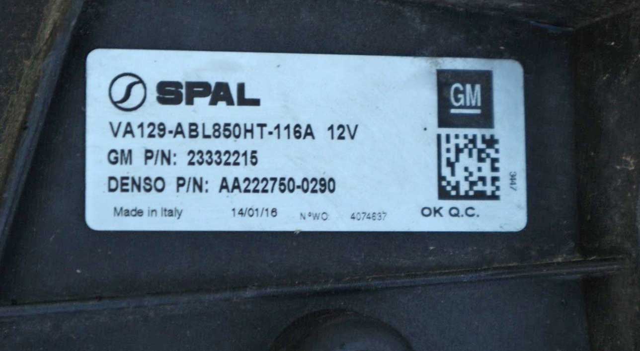 The fan pictured here is GM PN 23332215. Other GM part numbers for this fan will be 23455465 and 84100128. If you're shopping for one of these, be sure you're looking for the BRUSHLESS version (for the V8), since there were also apparently some ordinary BRUSHED versions made for V6 cars. AFTERMARKET VERSIONS As of 2026 this fan is also now available as an aftermarket part from what appears to be several sources. One is Dorman 621-984. Other aftermarket versions from various sources are found on eBay or other parts places by searching the above GM part numbers. I have no experience with any aftermarket ones. -- DIMENSIONS -- 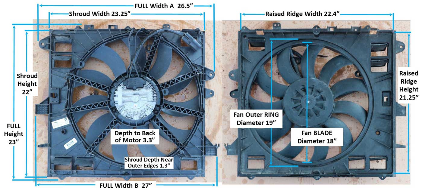 This fan will be called a "19 inch fan" by many people all over the internet. It's NOT REALLY a 19 inch fan. The actual fan blade diameter is 18 inches. The outer ring on the fan blade is 19 inches, but that ring does nothing to push air. So I think it's more accurate to call this an 18 inch fan, but if you like calling it a 19 inch, fine. Keep your fantasy. The connector on this fan is this 4-pole MALE plug below LEFT. This fan uses 3 wires, so only three poles are used on this plug. 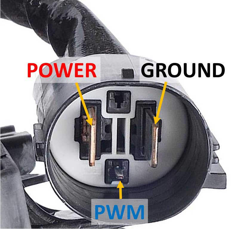
I found this matching FEMALE connector kit above after searching for Spal PN 30130628 in Amazon: https://www.amazon.com/dp/B07CTDGNGT. This is the same plug used for the Spal aftermarket fans and for the Jeep JK fan installation in this page. For those who buy a fan like this and want to test it using a simple PWM signal generator, this should help. CLICK HERE: Testing a Brushless Fan CLICK HERE: Activating a Brushless Fan
This fan has some fascinating performance. From internet info, I expected this fan would have a standard (posative polarity) PWM duty cycle ramp because there are sources on the internet which say that. The OPPOSITE is true. During my testing, I found this fan has an INVERTED PWM ramp (Negative polarity). So keep in mind the internet can be a liar. Negative polarity means LOW speed begins when duty cycle is near or below 85-90%. HIGH speed maximum is at 10% duty cycle. THIS FAN USES A 100 Hz PWM FREQUENCY. Camaro SS Brushless Fan Testing (2023) I bought and tested a used one of these, but this fan never got installed by me, so I don't have "installed/loaded" tests here. I do have some extra info about this fan from another user in the Dewitts section below. It shows this fan can pull 4188 CFM when installed with a radiator restriction in front of it. I put together these tests below in FREE AIR. Free air means there is no radiator or other obstruction to restrict flow. If this fan were to be *installed* with a radiator, intercooler and AC condenser in front of the fan, the CFM results would be considerably lower. I didn't get the chance to install this fan because I returned it due to some unreported collision damage.
A few tests were also done with my engine running for full charging voltage (14.5v). These tests were also with the fan in FREE AIR.
However if you do, I strongly recommend a high output alternator with dual V-belts or a good serpentine belt system with a lot of belt wrap around the alternator pulley. These last two tests above are shown in the below video (except for RPM speed). I found the low amp draw at 50% (3400 CFM free air) to be very impressive. The full power test with engine idling with my 170 amp Mechman alternator pulled the battery voltage down from 14.5v at to 13.7v. In my opinion, you really SHOULD NOT NEED TO RUN THIS FAN AT FULL POWER, except maybe for a trip to the sun. https://www.youtube.com/watch?v=kZ9Vi3JUjsA https://www.youtube.com/watch?v=-KEYcQFQwd4 Aiomest AN-846A anemometer purchased from Amazon: https://www.amazon.com/dp/B088QZ3689. You can see more about this tool and others in the Testing Tools section. The below video made in 2024 offers some information on using this Camaro fan for performance use. https://www.youtube.com/watch?v=n5KACPyNOzU VINTAGE AIR CUSTOM FANS with SHROUDS Here are some interesting custom fan assemblies that Vintage Air is offering. These all appear to have the big Spal 18 inch brushless fans mounted in custom, compact shrouds. These are not cheap, but it's a very nice effort by them and it gives you some very nice ready-made choices if any of these will fit your radiator. The reason I've placed these items in my page is to show more possibilities for these fans if you need something with a more compact shroud. Like other Spal fans, THESE USE A 100 Hz PWM FREQUENCY and have Negative polarity. The main Vintage Air web site does not appear to have easy-to-find links to these fans, but the links below should show you a full menu of all of them. vintageair.com/builder-series/CoolingFans vintageair.com/brushless-cooling-fans-and-shrouds Jon S. bought one of these fan/shroud combinations (Vintage Air PN 280478 found HERE) and did some testing. He sent me the below info. These tests below showing airflow were with the fan installed, pulling air through the radiator, transmission cooler and intercooler.   
More instructions can be found in a PDF for the above fan at https://vintageair.com/content/280480.pdf Below image is from that PDF.  Some Vintage Air fans available are shown below, which all use big Spal brushless fans. Vintage Air Fan PN 371252 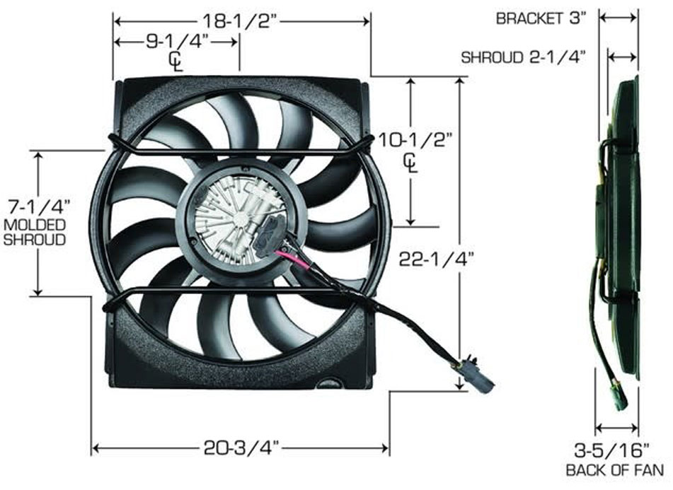 Vintage Air Fan PN 371253 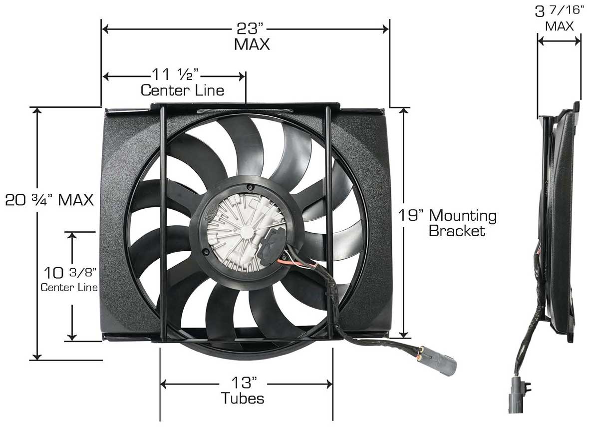 Vintage Air Fan PN 280479 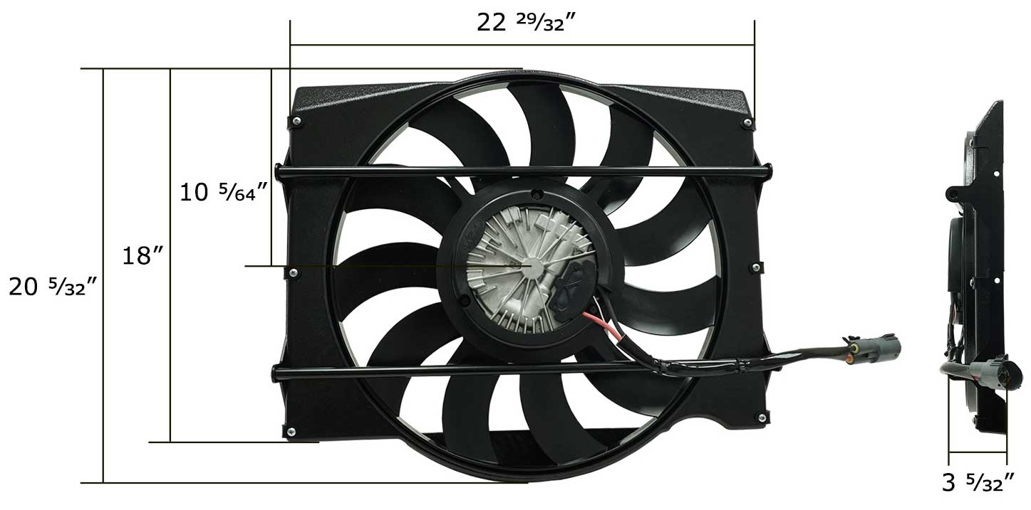 Vintage Air Fan PN 280483 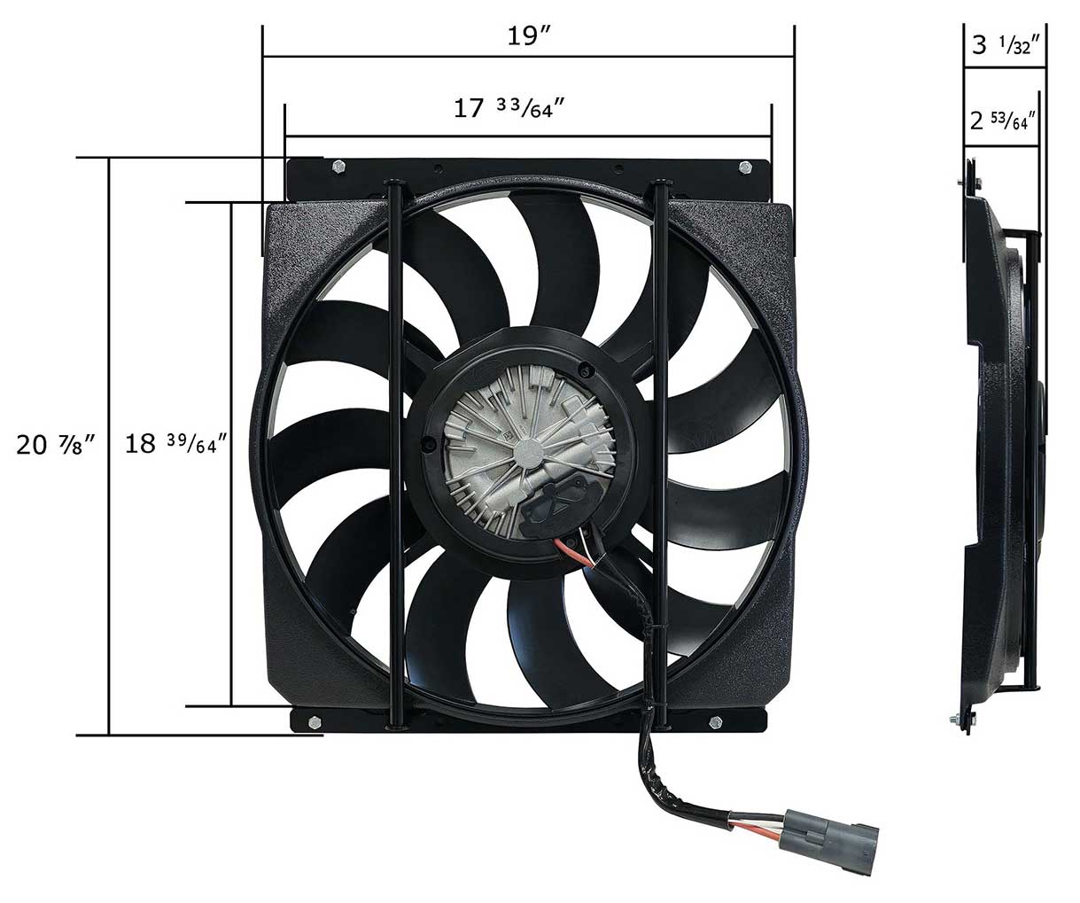 Here's a video showing one of these Vintage Air fans being installed in a classic truck. https://www.youtube.com/watch?v=m19BKpd1KEg Vintage Air is also offering "Smart" sensors for use with these fans. These are fixed temp sensors which are not adjustable.  Fan Sensor for 160 F thermostat. PN 113019: vintageair.com/custom/pn=113019 Fan Sensor for 180 F thermostat. PN 113021: vintageair.com/custom/pn=113021 Fan Sensor for 195 F thermostat. PN 113018: vintageair.com/custom/pn=113018 DeWitts Custom 18" Brushless Fan and Shroud This is a fan and shroud combination designed and assembled by DeWitts (a performance radiator builder) to fit a 2014-19 C7 Corvette. The fan appears to be a Spal 18 inch (with 800 watt motor) which I think is the same as found in late model Camaros (same as this one). The shroud is a custom aluminum part they have created. This package is very nice and quite expensive. Like other Spal OEM type fans, THESE REQUIRE A 100 Hz PWM FREQUENCY and have Negative polarity. 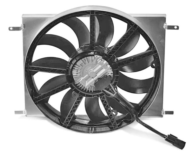 This item can be found here: dewitts.com/c7-corvette-19-electric-fan Note that they are calling this a 19 inch fan. It's actually an 18 inch fan. You can see my explanation in the Camaro fan section above. This fan has reportedly been tested installed behind a radiator pulling about 4188 CFM. Source: corvetteforum.com/forums/4314951-dewitts-19-fan -- DIMENSIONS -- 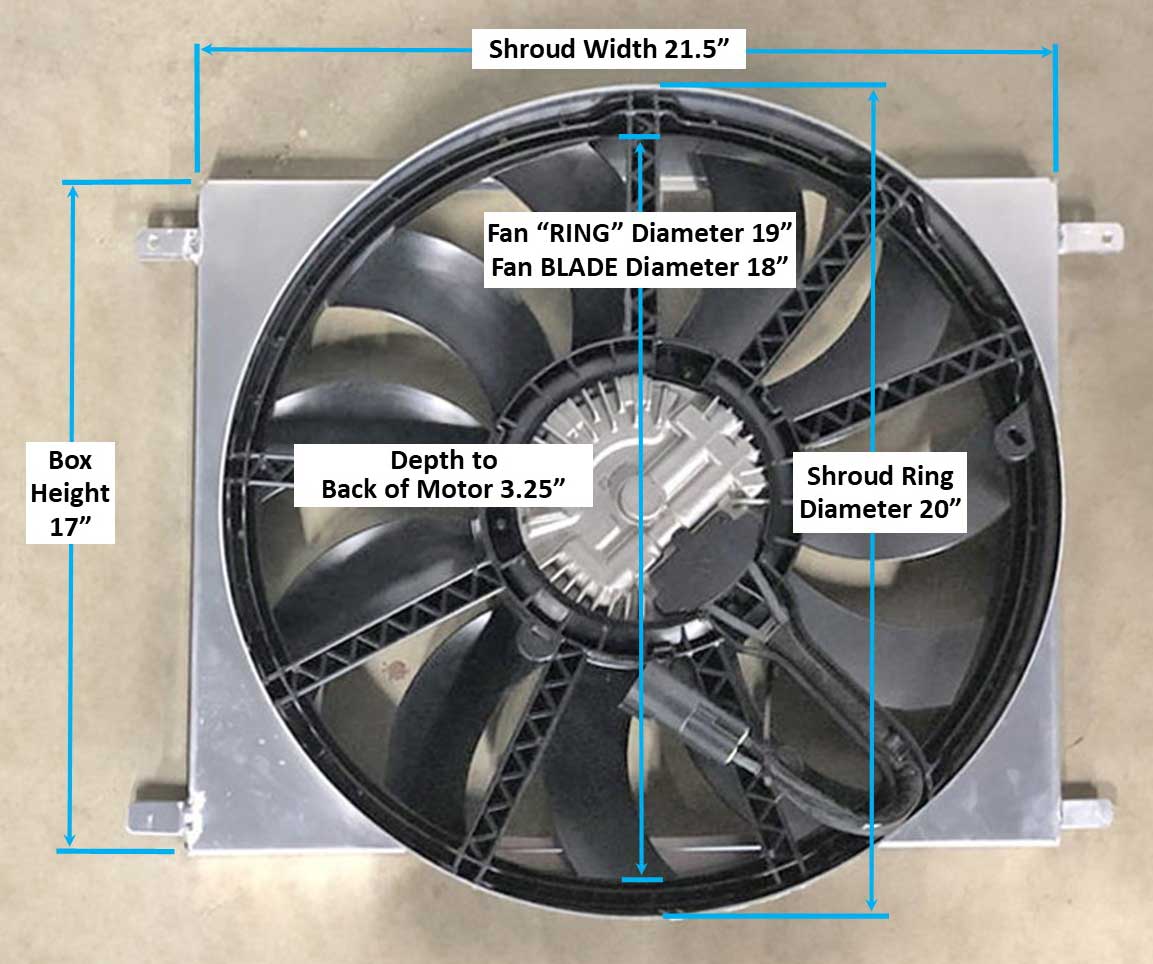 The connector on this fan is this 4-pole MALE plug below. This fan uses 3 wires, so only three poles are used on that plug. I found the matching FEMALE connector kit after searching for Spal PN 30130628 in Amazon: https://www.amazon.com/dp/B07CTDGNGT. This is the same plug used for the Spal aftermarket fans and the Jeep JK fan in this page.
The reason I have placed this fan above in my page is to show more possibilities using Spal fans if you need one with a shroud that's smaller than the big factory Camaro shroud. This type of compact fan-shroud combo *could* also be re-created by you if you have some fabrication skills. Also it could be turned 90 degrees and it just might be a decent fit for a factory sized Volvo 240 radiator. If you try fitting a fan like the above one to a standard Volvo 240 radiator, I'd be very interested in seeing how it was done. Stock Volvo 240 radiator dimensions. Volvo 240 Radiator Overall: 17.5 inches high, 22 inches wide, 2 inches deep.
2014-2019 Corvette C7 Z06 14 inch Brushless Fan These fans were made by Spal for GM. It appears two versions were made. One used a 500 watt motor for the C7 Stingray and a more powerful version used a 600 watt motor for the C7 Z06 (Source: forum.hptuners.com/SPAL-Brushless-Fan-Control-issue). Like other Spal OEM type fans, THESE REQUIRE A 100 Hz PWM FREQUENCY and have Negative polarity. A 14 inch fan may seem small, but when used with a strong 600 watt motor, it's likely this fan will pull plenty of air. Possible GM part numbers 15-81914, 84486697, GM3115306. Spal PN VA103-ABL600P-105A, which denotes the 600 watt motor (600P). The PN below right shows a 500 watt motor (501P). So be sure to check the PN if you're buying a used fan.  This fan might also be available as an aftermarket part made by TYC (China). TYC PN 624320, however the motor wattage is unknown. A version of this 14 inch fan has reportedly been tested installed behind a radiator pulling 2916 CFM. Source: corvetteforum.com/forums/4314951-dewitts-19-fan This link below doesn't have any Volvo content, but if you would like to see how this fan was fitted to a Honda S2000 radiator, see here: s2ki.com/forums/corvette-brushless-fan -- DIMENSIONS -- 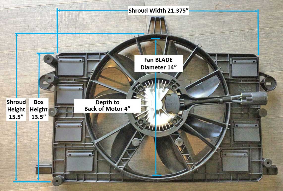 The connector on this fan is this 4-pole MALE plug below. This fan uses 3 wires, so only three poles are used on that plug. I found the matching FEMALE connector kit after searching for Spal PN 30130628 in Amazon: https://www.amazon.com/dp/B07CTDGNGT. This is the same plug used for the Spal aftermarket fans and for my Jeep JK fan installation project in this page below.
PROFORM BRUSHLESS FANS Proform brushless fans are relatively new to the aftermarket fan market. I don't have any first hand experience with them yet. As I find useful info I'll add it here. If you have any useful info that might help with this page, please email me: CONTACT. As of 2025 Proform is offering 10 inch, 12 inch, 14 inch and 16 inch brushless PULLER fans. A PULLER fan is one that will be placed behind a radiator. They also offer 10 inch, 12 inch and 14 inch PUSHER fans. Proform brushless fans requires a 110 Hz PWM FREQUENCY and have POSITIVE polarity. When I saw advertising info for Proform, I was skeptical of their CFM claims. Their web page claims their 14 inch brushless "Ultra Performance" puller fan (PN 67035) will pull 2900 CFM at 21 amps. If you've followed along very much in this page, you'll understand that sort of claim sounds pretty high for any 14 inch fan. But what's important in any CFM measurement is the method of testing and relative consistency between comparisons of other fans. 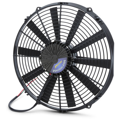 The below video from Fast Monty's Garage demonstrates that a 14 inch Proform can come fairly close to their claim IF the CFM is measured without any radiator resistance (in FREE AIR), but NOT very close if you add a radiator in front of it. So take this for what it's worth. Proform probably makes a good product. Perhaps they should take another look at their test claims. Keep in mind that the Proform 14 inch brushless fan has an overall outer dimension of 14.4 inches. Their page lists the actual fan blade diameter at 13.75 inches. The center hub is 4.25 inches. This 2025 video from Fast Monty's Garage will give you a very good education. It's a side-by-side fan comparison between a 14 inch Proform BRUSHLESS and a 14 inch Spal BRUSHED fan. https://www.youtube.com/watch?v=3_GvR8lCJoE Brushless PROFORM 14" vs SPAL Brushed 14" - Electric Radiator Fan Show Down! PROFORM BRUSHLESS FAN CONTROLLER https://www.proformparts.com/fan-controllers New for 2025 is this brushless fan controller. Adding the full speed manual override is a nice feature. They don't offer any info about the AC switch circuits (not in their instructions either), so I'm guessing that function probably turns the fan on 100% when the AC is on. 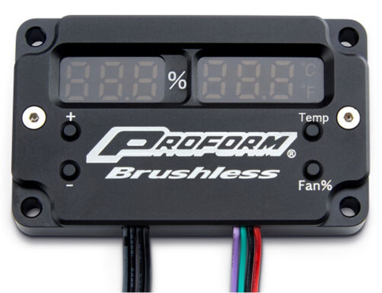 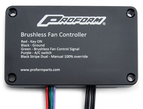 A video below from Proform offers a brief look. https://www.youtube.com/watch?v=Tc9SgySY2EA JEEP JK "19 inch" (actually 18 inch) Brushless Fan Plus my installation shown here into my Volvo 240. Separate installation of the WM Brushless Fan Controller is shown HERE. This fan is found on 2012-2018 Jeep JK Wrangler vehicles with a 3.6 liter engine. I bought a new aftermarket version of this fan and installed it in my car. This fan requires a 10 Hz PWM FREQUENCY and has POSITIVE polarity. 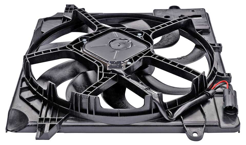
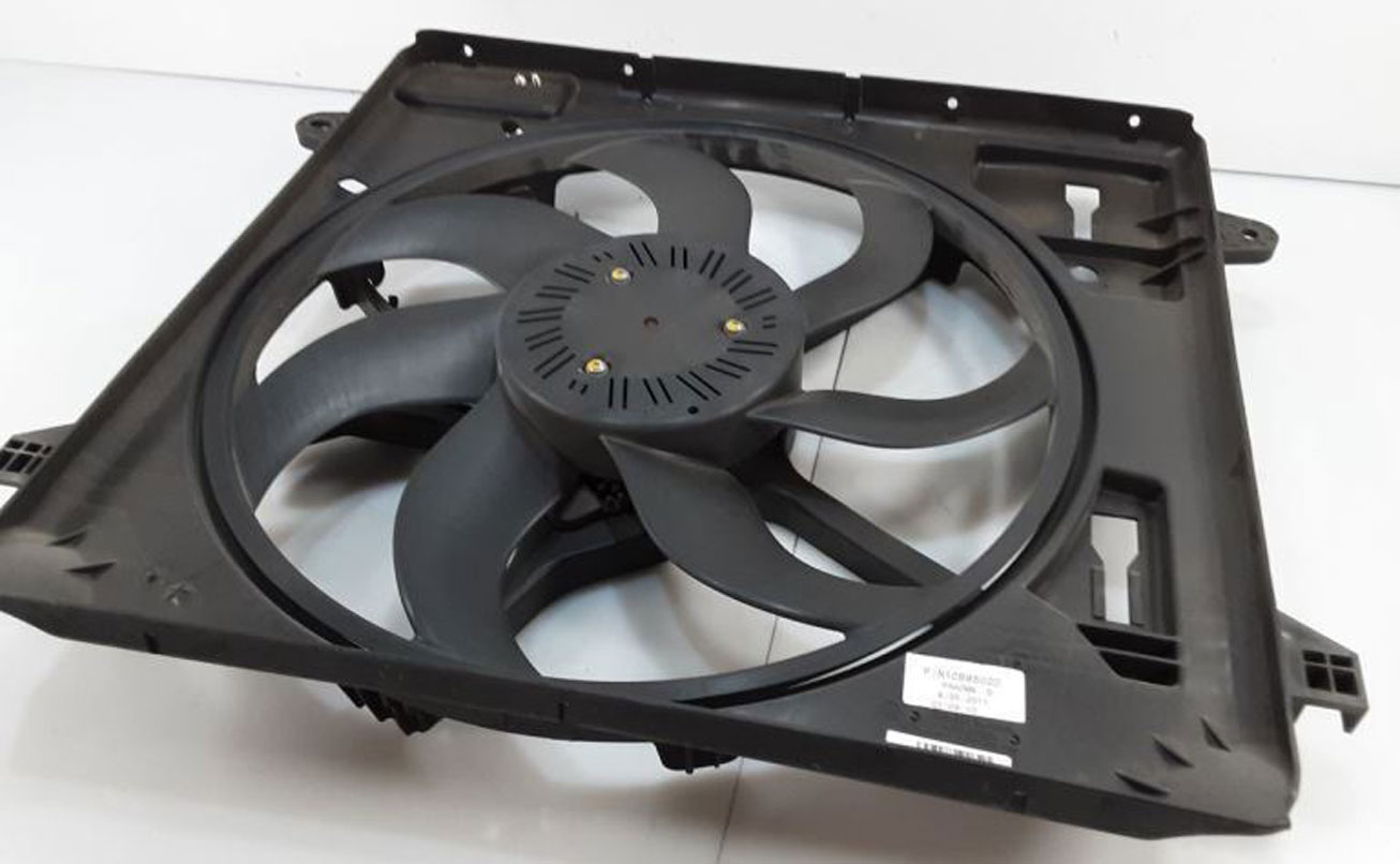 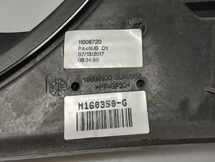
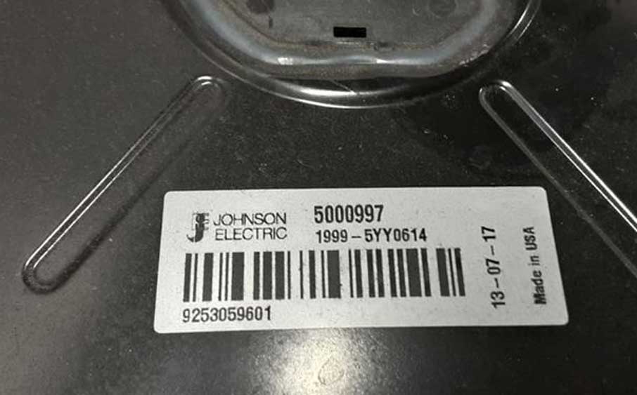
This fan is sometimes called the "Pentastar" fan on the internet. Some original factory fan labels are shown above. I believe the Mopar PN is 68143894AB, which I have not seen on any actual fan label. These labels above show the manufacturer as Johnson Electric and "Made in Italy." The original labels also show a date of manufacture, which will probably be sometime between 2011 and 2017 if you buy a used factory fan. AFTERMARKET VERSIONS of this fan are also available: Dorman 621-601 is shown below. Also I have seen at least one other aftermarket manufacturer (unknown who), which seems to be common on eBay. 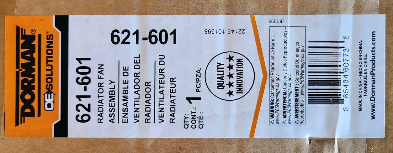 I bought, tested and have used this Dorman fan.  -- FAN DIMENSIONS -- 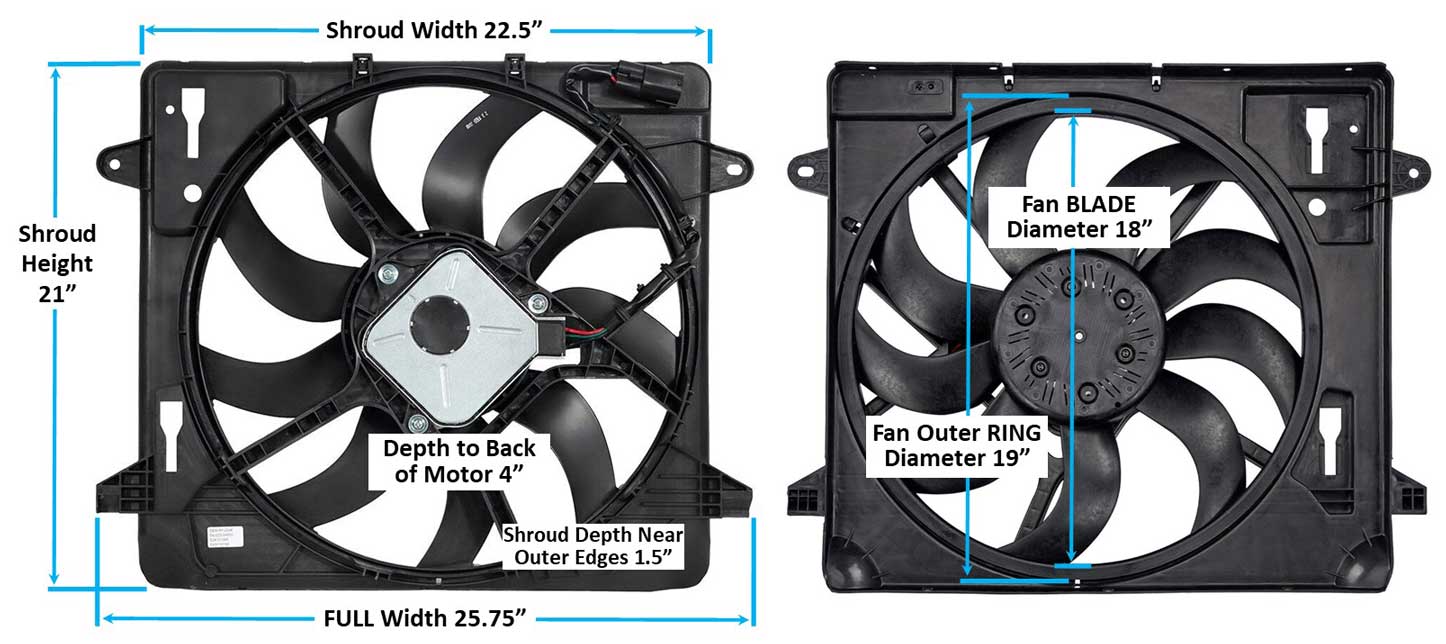 This fan will commonly be called a "19 INCH Pentastar" by lots of people on the internet. The actual fan blade diameter is 18 inches. The outer plastic ring on the fan blade is larger (19 inches across), but that outer ring does nothing to push air. So I think it's more accurate to call this an 18 inch fan. NOTE ABOUT DIFFERENT BLADE COUNTS: The above images in the dimension photo (which I stole from the internet) show a 9 blade fan. The Dorman aftermarket fan I bought has 7 blades. So I took a closer look at a number of used original Mopar fans on eBay and every one I found had 7 blades. So I'm not sure where the 9 blade fan is from. And I have no idea if 7 blades or 9 blades makes any difference in performance for this fan. I suspect not. CONNECTOR The connector on this fan is this 4-pole MALE plug below left. This fan has 3 wires, so only three poles on the plug are used. 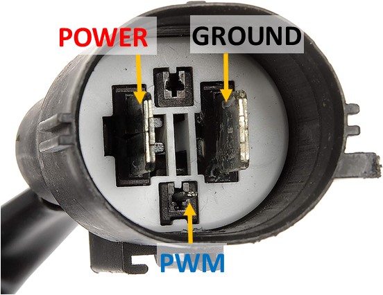
The matching FEMALE connector kit may be found by searching for Spal PN 30130628 in Amazon: https://www.amazon.com/dp/B07CTDGNGT. This is the same type of plug used for the Spal aftermarket fans and the Camaro fan in this page. The above kit came with several sets of terminals, which were made for different sized cable. I used the largest terminals with 10 gauge wire in my fan installation. 10 gauge is just fine for my short wires. The large terminals appeared to be large enough for 8 gauge if you want to go bigger.  A chart like this below might help if you're trying to determine an appropriate cable size. 
For those who buy a fan like this and want to test it using a simple PWM signal generator, this should help. CLICK HERE: Testing a Brushless Fan CLICK HERE: Activating a Brushless Fan The below video from 2016 discusses this brushless Jeep fan and compares it to the previous 17 inch BRUSHED fan that this fan replaced in Jeeps beginning in 2012. https://www.youtube.com/watch?v=2so93C02W9Q I don't know what the WATT RATING is for the Dorman motor, but it appears not quite as powerful as the Camaro fan I tested. If I had to guess, I would say around 600w. This fan also ramps up a bit slower from stopped than the Camaro fan. My initial plan was to install the Camaro fan, but the one I bought was damaged and I sent it back. Then I changed to this Jeep fan. Please don't think I'm disappointed in the lesser CFM. I'm not. My previous fan was the brushed Lincoln Mark VIII fan and this Jeep fan SURPASSES the performance of the Lincoln fan while using less current. This fan has a STANDARD PWM ramp (Positive Polarity), which is opposite of the Camaro fan I tested. This means LOW speed begins when duty cycle is at 10% or higher. HIGH speed maximum is achieved at 85% or higher duty cycle. THIS FAN REQUIRES A 10 Hz PWM FREQUENCY. I've been told a 10 Hz frequency is also used by Mercedes. Jeep JK Brushless Fan Testing (2023) I figured since I was installing this fan I'd try to add do some extra testing. A bunch of speed and CFM tests were done at two different voltage levels (12.7 volts on battery only and 14.5 volts with engine running and charging). These tests were also done with the fan in FREE AIR and also INSTALLED/LOADED (installed results below are in BOLD). FREE AIR means there are no obstructions (this fan pulled 5000 CFM in FREE AIR). INSTALLED means there's a radiator, intercooler and AC condenser in front of this fan. This makes a big difference. It can be a difference of 20% to 25% or more in reduced airflow due to the restriction of having to pull air through these things. Also of note, the lower 4 inches of this fan as installed has a barrier that might have some minor obstructing affect. That barrier can be seen in the installation photos below.
https://youtu.be/ZOdyyxAyGgw Since this fan is taller than my 17 inch tall radiator, several inches of the shroud will hang below the radiator. So that portion must be sealed off on the radiator side with a barrier wall at the bottom. 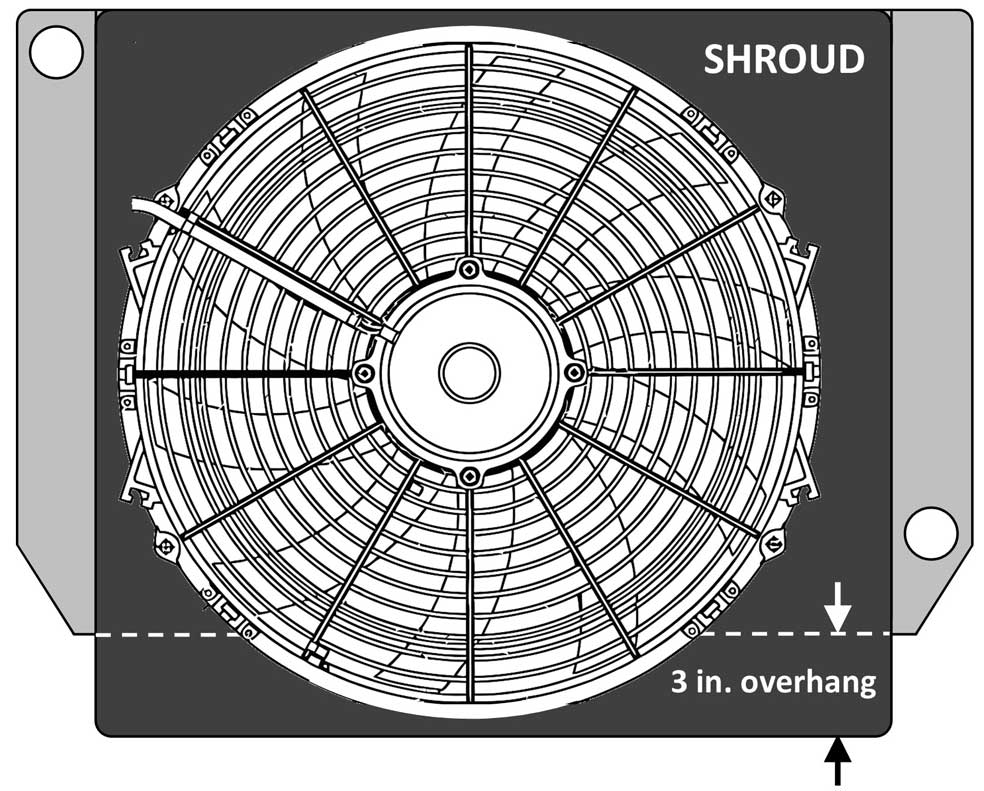 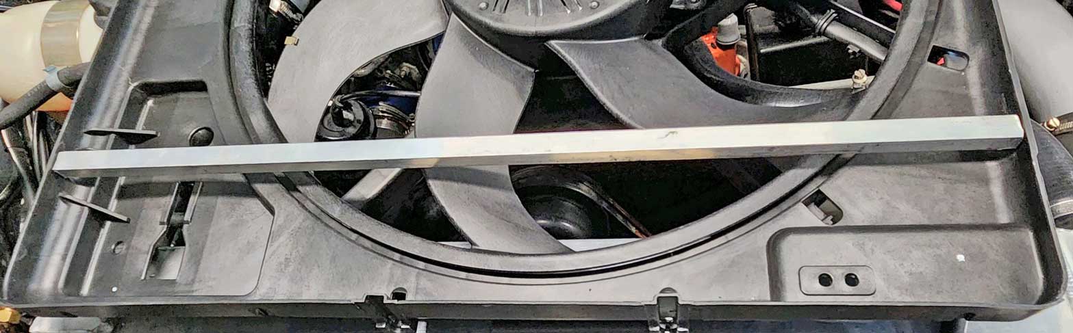
I began with a piece of aluminum angle bar stock to give the barrier stability. It looks like it's really close to the blades in the above photo, but it's actually more than 1/2 inch. 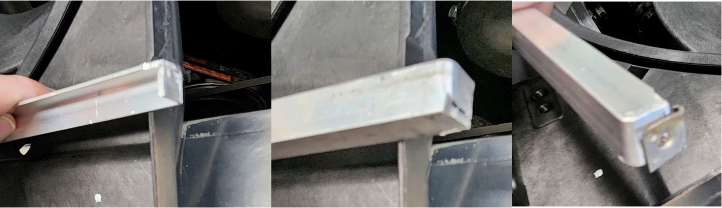 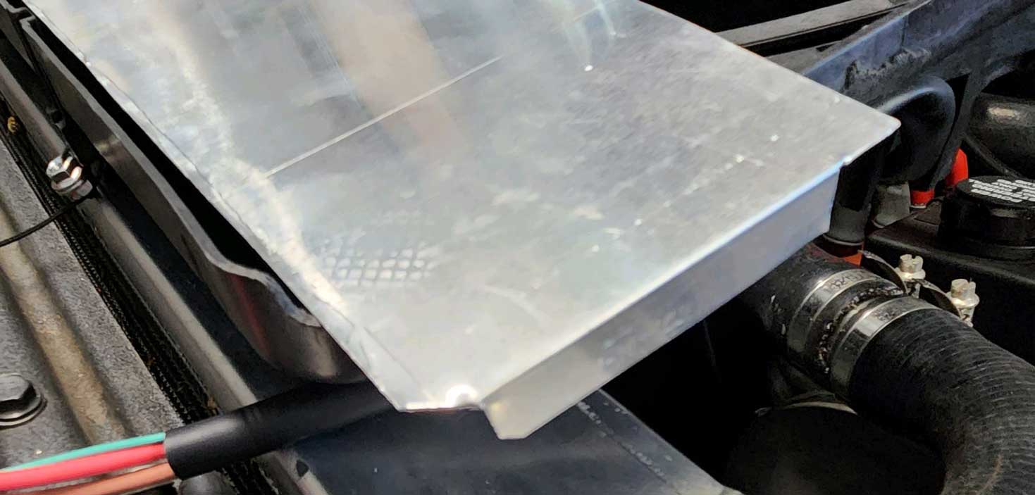
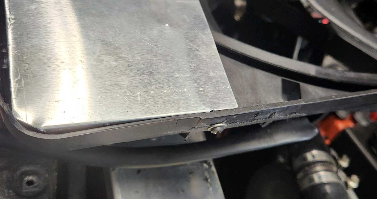
Some thin aluminum sheeting was fitted to close off the bottom. 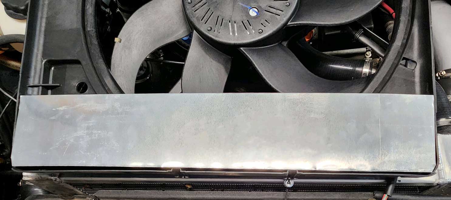 Edges sealed with duct tape. And some useless holes in the shroud were covered with some pieces of the ABS plastic (with epoxy). 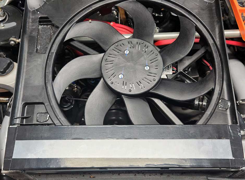 View of the bottom from the back-side of the fan. 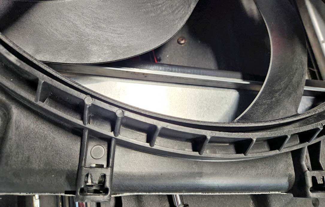 Top brackets were made with some aluminum straps. The photos below show how the top of the shroud has a lip that comes over the top of the radiator. This made for a very nice fit 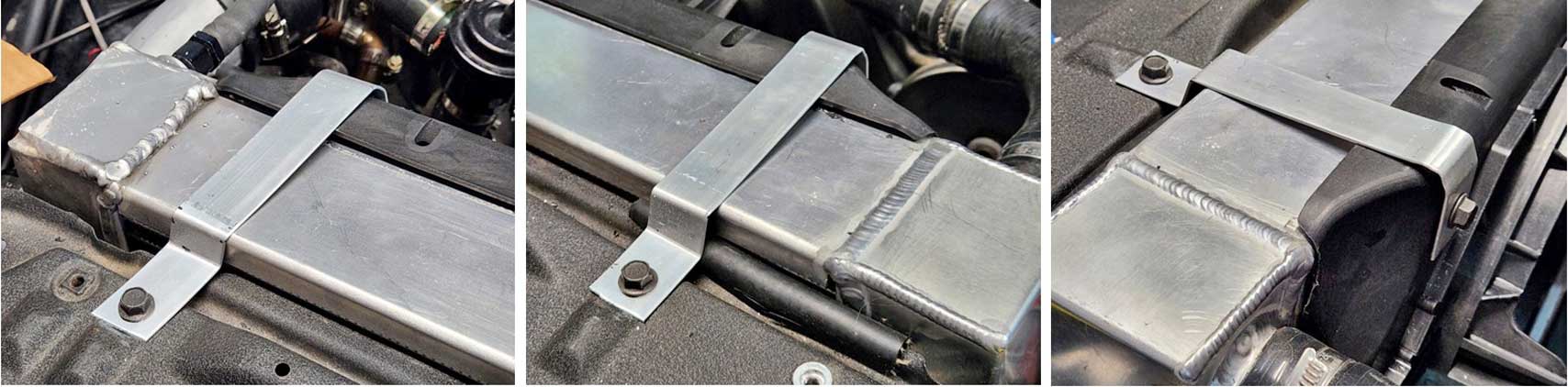 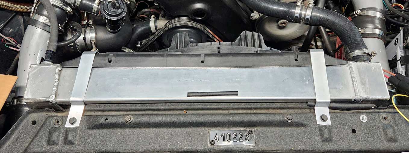 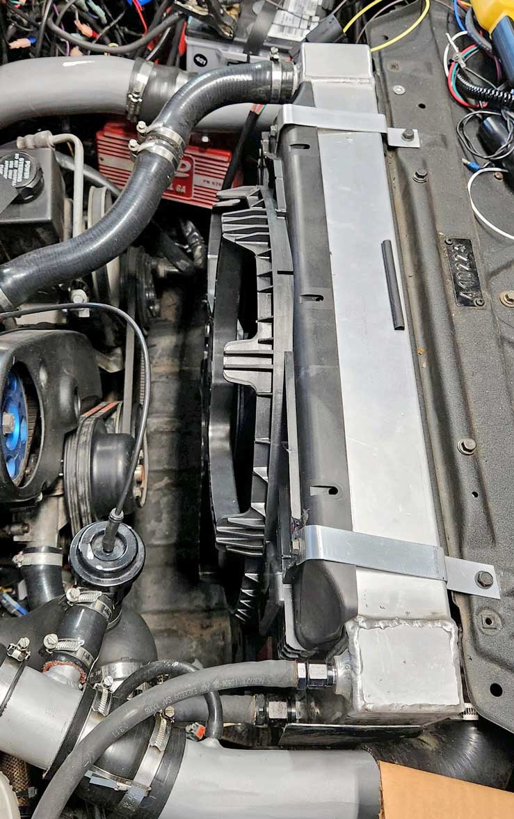
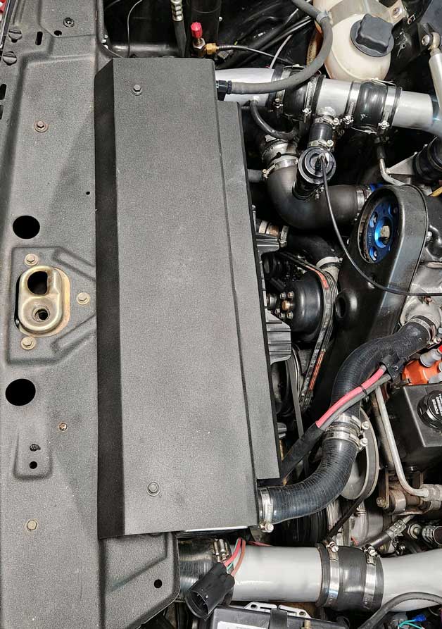 There is lots of EXTRA room between the fan and engine. There's even more room now, compared to the bigger Mark VIII fan I used to have in there. 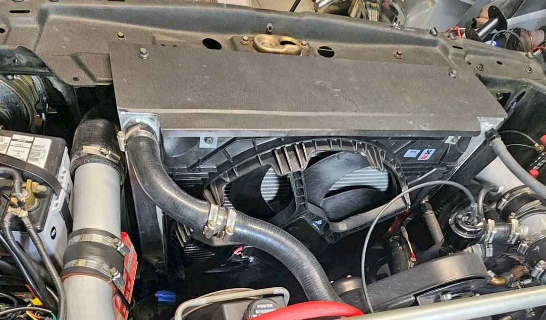 This fan has so far been used in my car for about 8000 miles of cross-country driving in a variety of hot summer weather. Verdict: IT'S AWESOME. It needs very little power to keep things nice and cool. Further installation info the fan controller can be found further below in the Fan Controller Section HERE. Should a FUSE be used with a Brushless Fan? A fuse is not required, but it adds a level of safety. A BIG fuse is recommended. And make certain you buy a high quality fuse holder, not a cheap no-name one. This is a Maxi Fuse holder from Blue Sea Systems with a 50 amp fuse. It's placed between the battery positive and the fan. Click HERE for more about this FUSE. Electrical connection: I used 10 gauge cable on the left side of this plug below for wires going to the battery. 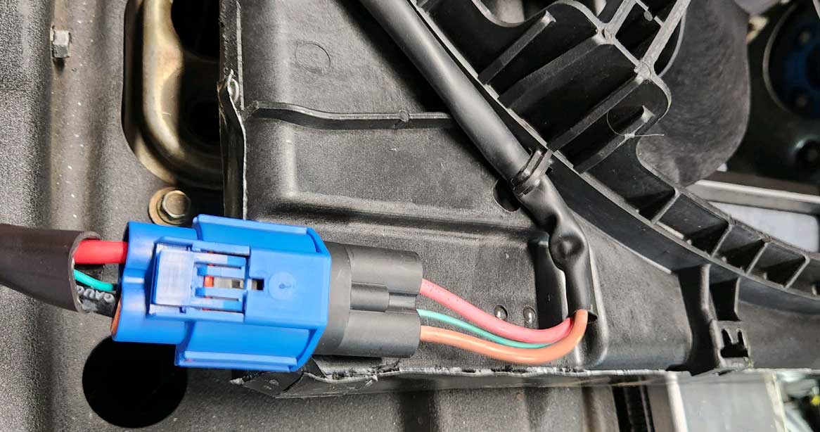 .
.. CUSTOM RADIATOR If you're curious about my radiator in my Volvo 240, I had a new custom one made by Griffin Radiator in 2022. 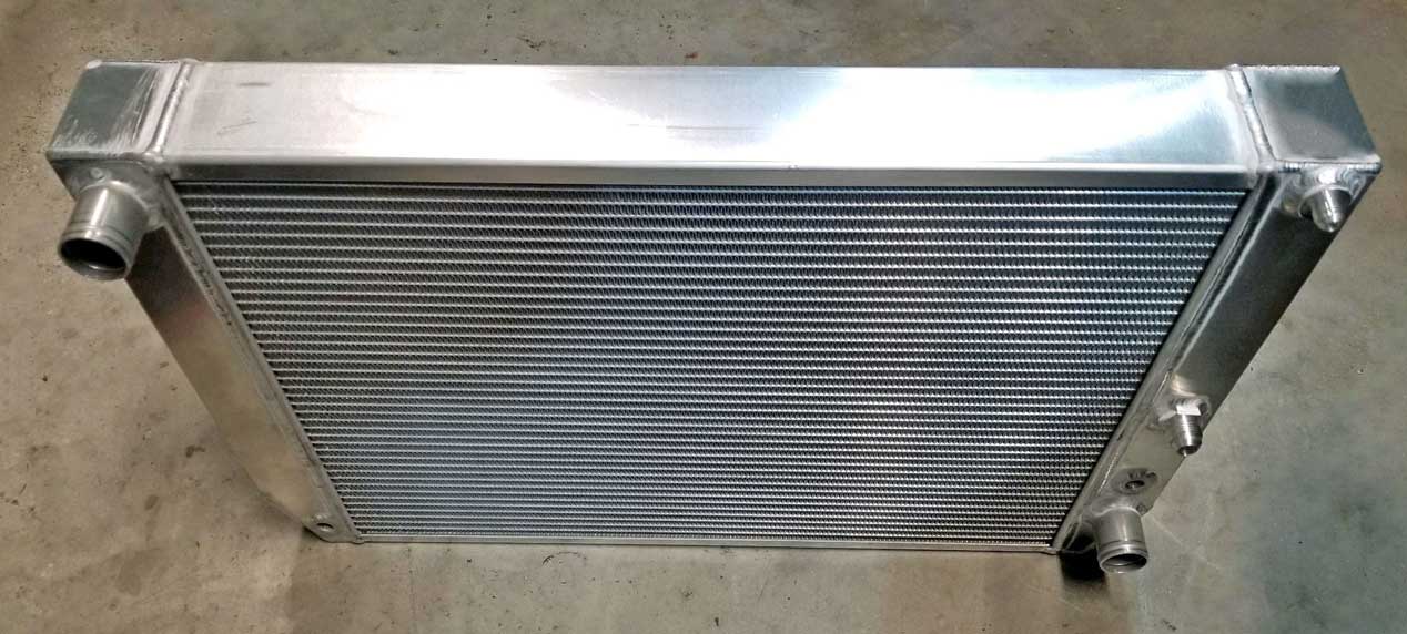 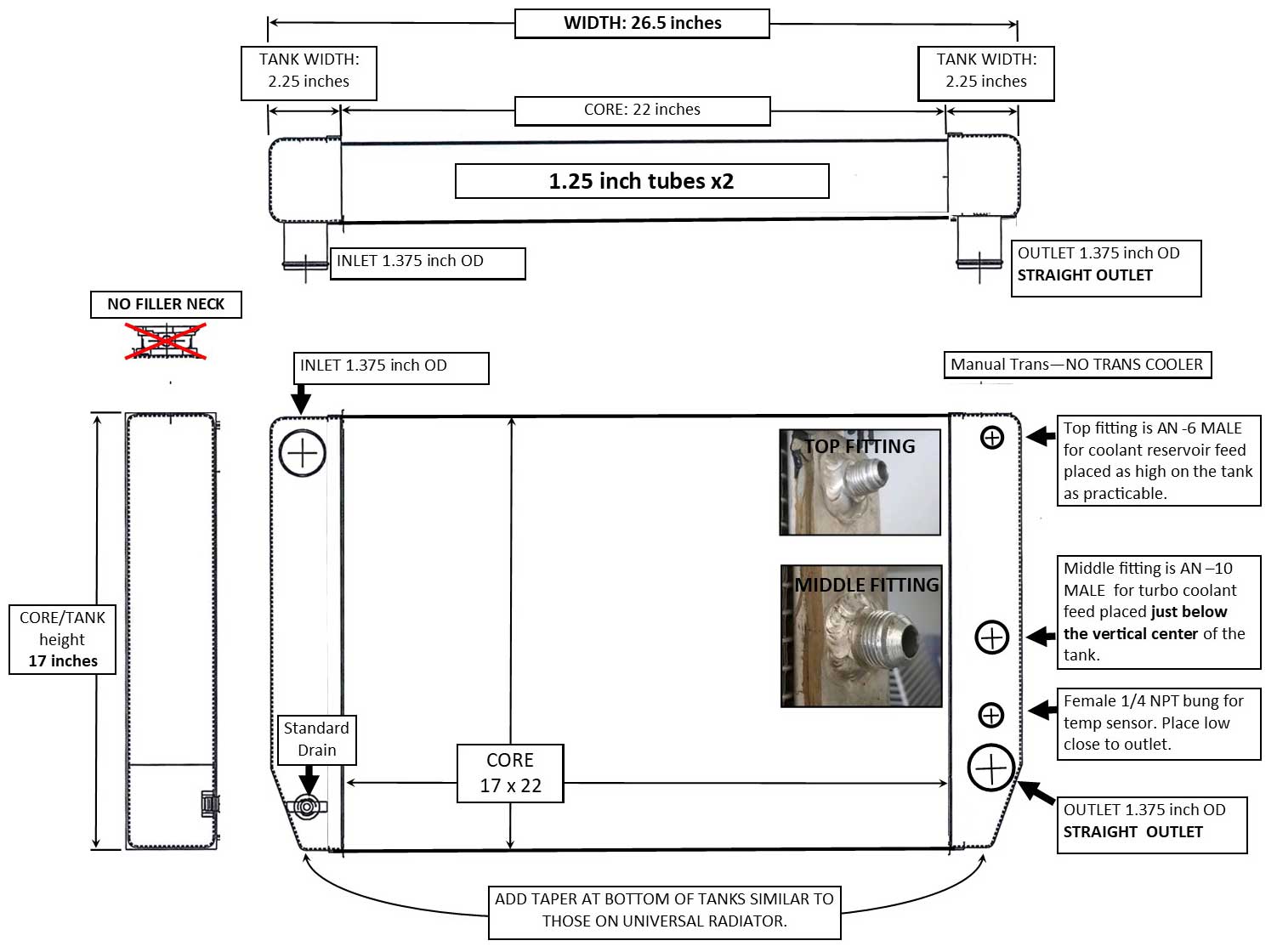 Dual 12 inch Chevy Volt Brushless Fans This fan assembly is found in a 2011-15 Chevy Volt. This fan assembly is too wide for most Volvo 240s, unless you have a much wider radiator than stock. Since this fan is popular among hot-rodders, the info is a good addition here. Like other Spal OEM fans, THESE REQUIRE A 100 Hz PWM FREQUENCY and have Negative polarity. 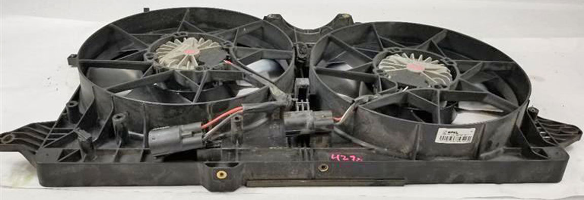
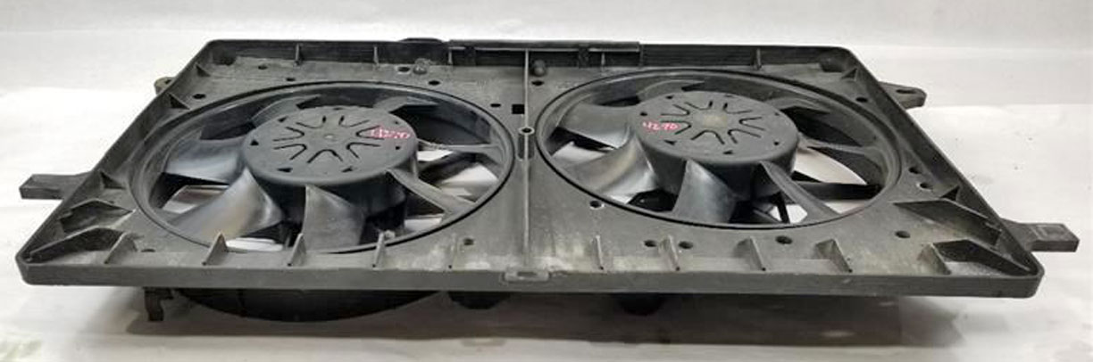  These fans were made by Spal for GM, so an original Chevy Volt fan assembly will have a Spal label like these. Original PN: GM3115258. Spal rates their 12 inch aftermarket brushless fans (PN VA89-ABL320P/N-94A) at 1800 CFM (at 13v) per fan, using about 23-27 amps at full speed (per fan). So I would expect these fans combined to pull up to about 3600 cfm. There are also AFTERMARKET Chevy Volt fan assemblies that are made by Four Seasons or TYC. TYC PN 623170: www.amazon.com/TYC-623170. FAN DIMENSIONS 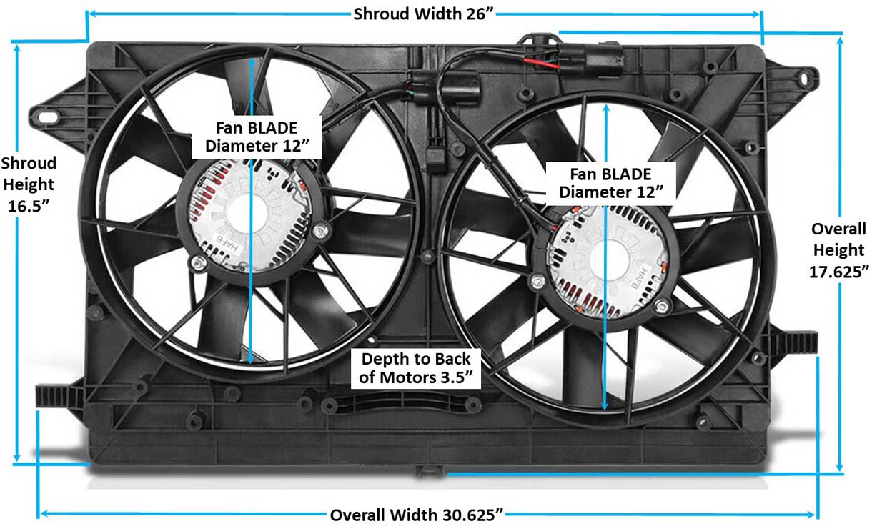
The connectors on this are a 4-pole MALE plug. These fans have 3 wires each, so only three poles are used. The matching FEMALE connector may be found by searching for Spal PN 30130628 in Amazon: https://www.amazon.com/dp/B07CTDGNGT. Here's one of these fans being used for a project. s10forum.com/threads/brushless-spal-upgrade This installer used a Widget Man controller like my installation. Like other Spal OEM fans, THESE REQUIRE A 100 Hz PWM FREQUENCY and have Negative polarity. Here's a video of these fans: https://www.youtube.com/watch?v=8EYu5jVBvKA Activating a Brushless Fan You got to see a preview of one way a brushless fan can be activated in the Spal section. This section below will go into much more detail.
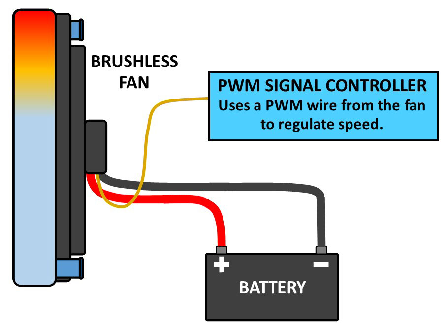 Keep in mind that there are a number of PWM fan speed controllers available now, however many are specifically made for DC BRUSHED FANS. Those controllers are not designed for use with a brushless fan, because the way they connect to a fan is very different. Brushed fans are not controlled the same as brushless fans. If a brushed fan controller manufacturer claims theirs will work for both brushed and brushless motors, that should be questioned and verified. This question is discussed more in a section below. Feel free to ask me for clarification or if you have a comment, please email: CONTACT. A BRUSHLESS DC motor has at least three wires. 1. Power to Battery Positive 2. Ground to Battery Negative or chassis ground. 3. PWM signal wire. 4. A 4th wire may be present on some brushless fans (Spal aftermarket for example). It will probably be an "Analog" signal wire used for other options. Controlled by a PWM SIGNAL A PWM signal (Pulse Width Modulation) is used to communicate with a brushless fan. It uses a Frequency Speed combined with a Duty Cycle to activate and regulate fan speed. A PWM signal is generated at a specific frequency, which is measured in Hertz (Hz). A Hertz frequency will be measured by the number of cycles in one second. The below image example is 10 cycles in a second, so this would be a frequency of 10 Hz. 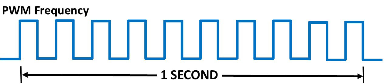
A 10 Hz frequency is used by the Jeep JK brushless fan and also by Mercedes Benz. A 100 Hz frequency is used by Spal and Volvo fans (and some others). A simple explanation of a duty cycle is to think of it this way. (BELOW IMAGE of 25% duty cycle): A 25% duty cycle can be viewed as a voltage signal that quickly pulses 25% ON and then 75% OFF. The fan speed is changed or regulated by the duty cycle varying the ON-OFF relationship. It can be changed or varied from 0% ON to 100% ON and 0% OFF to 100% OFF. 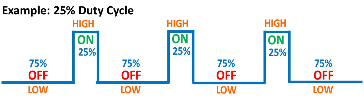 Using this 25% duty cycle example above, this would run a POSITIVE polarity fan at about 25% speed. POLARITY (Posative or Negative): Some brushless fans are designed to accept a POSITIVE polarity duty cycle signal. Some are designed to use a NEGATIVE polarity duty cycle signal. A fan with POSITIVE POLARITY: If you have a fan which speeds up as the duty cycle is increased (i.e.: low speed at 10%, high speed at 90%), then that fan has POSITIVE POLARITY. This type of fan reads and responds to the voltage "ON" portion of the duty cycle at the TOP (in below image). A fan with NEGATIVE POLARITY: This type of fan will slow down as the duty cycle is increased (i.e.: high speed at 10%, low speed at 90%). This type of fan reads and responds to the voltage "OFF" portion of the duty cycle at the BOTTOM (in below image). Using this 25% duty cycle example below, this would run a POSATIVE polarity fan at about 25% speed or a NEGATIVE polarity fan at about 75% speed.  Can a NEGATIVE Polarity Fan be used with a POSITIVE Polarity PWM signal? No, not normally. However, there are ways to convert it. It's possible to INVERT the polarity of a PWM signal using a conversion device. There are some devices SHOWN HERE which can do this. In the below video, an inexpensive PWM signal generator is used to test and run a 2010-2012 Ford Fusion brushless fan. The user has the frequency set for 100 Hz. Then he activates and varies the fan speed by reducing or increasing the duty cycle to different percent levels. As mentioned previously, some fans use an INVERTED PWM signal (Negative Polarity). This one in the video is a good example of that. This fan comes on at 85 or 90% (slow speed) and then speeds up as the duty cycle is reduced, with full speed at or near 10% duty cycle. https://www.youtube.com/watch?v=hMEXpVuxNhk
Activating a BRUSHLESS Fan using a BRUSHED Fan Controller??? Can you activate a BRUSHLESS fan using a controller designed for a BRUSHED fan? I don't know for sure YET, but my first thought was probably NOT. Am i WRONG? 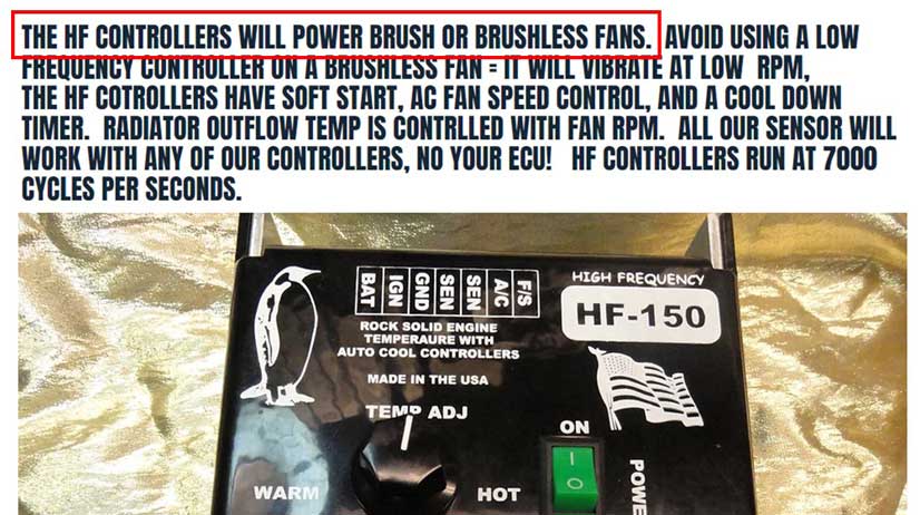 I began using an AutoCoolGuy controller for my Lincoln Mark VIII brushed fan in 2018. More about that is in the Cooling Fan Project Page 1 HERE. If you look at the Autocoolguy site, he claimed (ABOVE) his controllers will control BRUSHED or BRUSHLESS fans. Since I don't know how this is done with a BRUSHLESS fan, I sent him an email and asked. Darryl at Autocoolguy told me that, "if you have a brushless fan, which can be made to run at full-speed (like a normal fan) by connecting certain wires to power and ground, then the fan speed can be controlled using an Autocoolguy controller." That's it. He would not offer any further explanation. From my research so far, very few BRUSHLESS fans can be made to run at full-speed. Usually these are the the fans with FOUR WIRES (such as Spal aftermarket brushless fans). On a 4-wire Spal brushless fan the two smaller wires are a PWM wire and an Analog wire. If you want to dive it, you can review the below linked document for Spal Drive Control Modes, it will explain how a Spal aftermarket brushless fan (which has 4 wires) may be connected without a controller or sensor in a number of specific ways. Some of these connections will force the fan to run at full-speed (similar to a normal DC brushed fan). spalautomotive.it/DRIVE+CONTROL+MODES.pdf Two such listed "Drive Modes" (Interface Mode 1 and Interface Mode 2) are activated by connecting the power and ground cables normally to the battery, then the Analog wire is connected to the power cable and the PWM wire is connected to ground, as illustrated below. 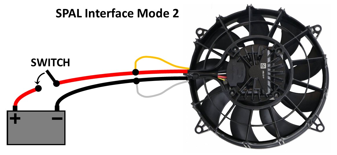 When I sent a follow-up email to Darryl at Autocoolguy and asked him if he could provide a more specific example of how one of his controllers can connect to and regulate brushless fan speed, he never responded to me again. So my only guess is maybe he means for his controller to be connected to the fan in the same manner as a brushed fan is connected? Using the ground cable to the fan as the PWM speed regulator??? I have no idea if a brushless fan will respond to this and I think it might be a mistake to try. It would be a shame if this caused problems or damage to a brushless fan or the controller. Also the question of polarity comes to mind. I would love to offer a better explanation here, but he it appears Darryl gets really annoyed if you send him MORE THAN ONE email question. He has never responded to me since. THE FULL ANSWER IS STILL NOT KNOWN. If anyone knows more, please email me: CONTACT. BRUSHLESS FAN CONTROLLERS There are a number of aftermarket modern engine management systems that will offer programmed (or programmable) PWM signal outputs for activating a brushless fan. Some of them can be fully customized. Also some OEM engine management systems will offer this, such as GM LS engine systems. I will not be going into detail on LS systems, since there's a lot of info and each system is different. For now, I'll discuss the below STAND-ALONE controllers.
DELTA-PAG I've listed more detailed information about the Delta-PAG brushless controller in the above Delta-PAG section. I have not personally tried one of these fans or controllers. I would welcome your comments if you have any to offer. SPAL I have already discussed the Spal "Smart" Sensors in a previous section. Those were designed for Spal Plus aftermarket brushless fans, but they may be used for other brushless fans, as long as the fan uses a 100 Hz PMW frequency and a STANDARD duty cycle ramp (Positive Polarity). These sensors will generally NOT be compatible with a any brushless fans with negative polarity, unless you use a device that can modify or invert the polarity, such as these devices LOCATED HERE. Lingenfelter VSFM-002 Variable Speed Brushless Fan & Pump Temperature & Speed Controller Lingenfelter offers a programmable controller:lingenfelter.com/L460320002.html. They have a detailed PDF user manual at: lingenfelter.com/PDF/L460320002.pdf. Size of this controller is 3.6 x 4.3 inches. The below diagram was found in their user guide. 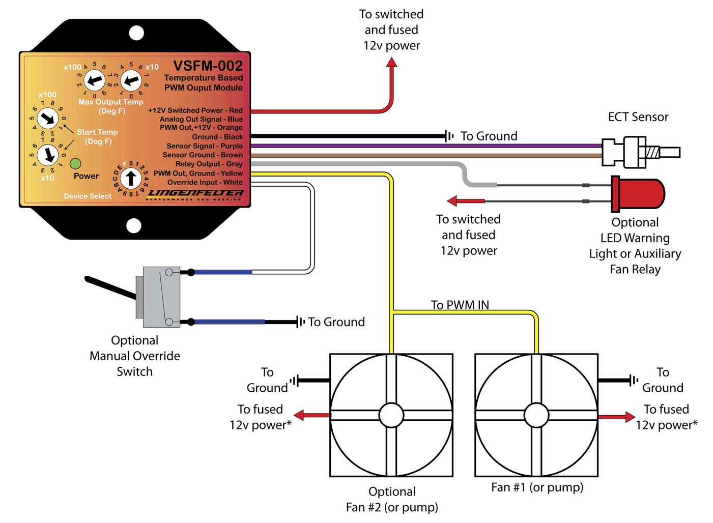 This controller appears to be quite versatile. A large number of differente OEM and aftermarket temperature sensors can be used with it. It can be made to control a wide variety of brushless fans from a number of different manufacturers, including OEM fans from Spal or Bosch or most other makes. It offers the option of an override switch (FULL-SPEED switch). If you need an AC override, it can be made to trigger a fan to run at FULL-SPEED when the AC is activated. The only draw-back I see for this controller is that the AC override DOES NOT OFFER an ability to select any speed other than FULL-SPEED. If I'm using a super high-output fan, I prefer to not have it run at FULL-SPEED unless necessary. It might not be necessary to use a big, powerful fan at FULL-SPEED when using AC. Having an option for something less extreme for the AC, such as maybe 50% speed, would be nicer. I have emailed Lingenfelter a number of times to ask some questions about AC stuff, but they don't respond. The below video was made by JeepSpeedShop.com, who does custom engine installations in Jeeps. In this video they show a special version of the above Lingenfelter controller, which appears to have been modified for them by Lingenfelter with a special custom feature which offers an optional fan AC override to run the fan at 30% when activated. This shop has begun shop offering this controller here: https://jeepspeedshop.com/product/lingenfelter-controller/ The only draw-back of this conversion I'm aware of is mentioned in the video, which says this special feature eliminates the optional manual override toggle switch option (for full power), which the original controller normally comes with. https://www.youtube.com/watch?v=j4tlqvVu_Vg
Proform Brushless Fan Controller I have placed info for this controller in the Proform Brushless Fan section. Davies Craig PWM Brushless Fan Controller This brushless fan controller and electric water pump controller is available from Davies Craig in Australia. https://daviescraig.com.au/product/variable-speed-controller-brushless-thermatic-fan-ewp-with-18-npt-sensor-0551 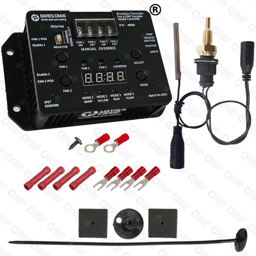 This controller reportedly requires the use of a brushless fan (or pump) using POSITIVE PWM polarity only. If a NEGATIVE polarity fan is to be used, a device can be used to convert or invert the PWM signal for the fan, such as this WM Digital Signal Converter (SQC2). Widget Man Universal PWM Brushless Fan Controller I began using one of these in 2023 for the Jeep brushless fan installation in my Volvo 240. That installation begins HERE. This section below will go DEEPER into the installation, functions and programming of this controller. When I first saw this item on eBay I was skeptical, mostly because the price was low compared to others. After reading more about it, and after thoroughly reading the extensive instructions, I thought it was worth a try to see what it could do. So I bought one.
If you're old-school and used to running an ON-OFF fan switch and sensor in your radiator to control an old BRUSHED fan, then something like this which uses variable temperature sensing for variable fan speeds will be a big step forward in technology. So even if you're running an old two-speed fan setup and you think you've really stepped into the future, think again and keep reading. This controller can control brushless fans with POSITIVE or NEGATIVE PWM Polarity. One nice feature that helped my decision was an optional Force-On feature which can be selected for 50% or 100% fan override when the AC is activated. I've mentioned previously how such an AC speed feature was missing from most other brushless fan controllers. This is an optional setting where you can trigger either a FULL-SPEED override or a 50% override. If the 50% override is triggered, the fan will run 50% higher than the current speed setting. So for example, this means if the fan speed is "OFF" (engine not warm yet), then the 50% override will run the fan at 50%. If the fan is already running at 25%, then the 50% override increases it to 75%. Also the seller of this device was VERY RESPONSIVE to emails and he has freely offered some great suggestions. This was very refreshing to someone like me who was still in a steep learning mode when it came to brushless fans and I certainly had questions. 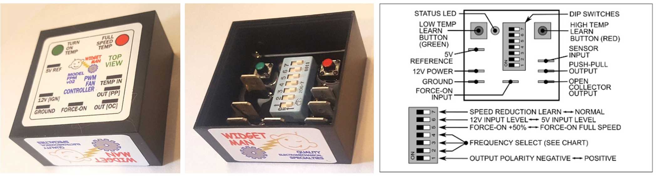 This item (Universal PWM Brushless Fan or Pump Controller) can be found at: https://gkgoodcheapparts.com/products/fpm-brushless-fan-control Direct link for PDF instructions: https://drive.google.com/file/d/pli=1 Other useful devices from this seller can be found at https://gkgoodcheapparts.com. NOTE: This controller is sometimes referred as an "FPM" in the Widget Man literature (maybe it refers to "Fan Pump Module?"). Optional Universal Temp Sensor In addition to the above controller, I purchased a universal temperature sensor. I ended up NOT this sensor. I found that using my factory Volvo temp sender was much simpler.  This universal temp sensor is optional and not required. You can easily use almost any factory or aftermarket sensor with the Widget Man controller, but I thought I just might want to try this sensor, so I bought one. In the end I DID NOT use this sensor. Instead I used my original Volvo coolant temp sender in my engine (which is detailed below). This Widget Man RTD Temperature Sensor above is basically a universal sensor, which can be used instead of using a temp sensor you might already have in your car: https://gkgoodcheapparts.com/products/widget-man-fpms-ring-mount-rtd-temperature-sensor. I bought it to learn how it works, in case it became a good option for this project or maybe this info will help someone else who sees this. If you're curious, an RTD (Resistance Temperature Detector) is a passive device in which the resistance output changes as temperature changes. The resistance vs temperature relationship is reliable and repeatable. This sensor requires power. That power should be a consistent voltage if possible. If your charging system voltage at the battery moves around with load changes (more than a few tenth of a volt), a sensor like this would benefit from a stable regulated power supply. The below device could be considered. Widget Man says this sensor can be placed anywhere, but they recommend the placement to be near an existing coolant sensor or near the thermostat housing, or even bolted to the thermostat housing. Alternately, you can use many other factory or aftermarket sensors with this controller. I ultimately decided to use the original VDO Volvo temp gauge sender in the cylinder head of my 240, which is shown a further below. Optional Adjustable Power Supply This Widget Man adjustable power supply is an optional item: https://gkgoodcheapparts.com/products/adjustable-sensor-power-supply-with-built-in-pullup-resistor. It's not required, but it can be useful if you think you need to more accurately stabilize voltage to your controller. I DID use one of these in my installation. 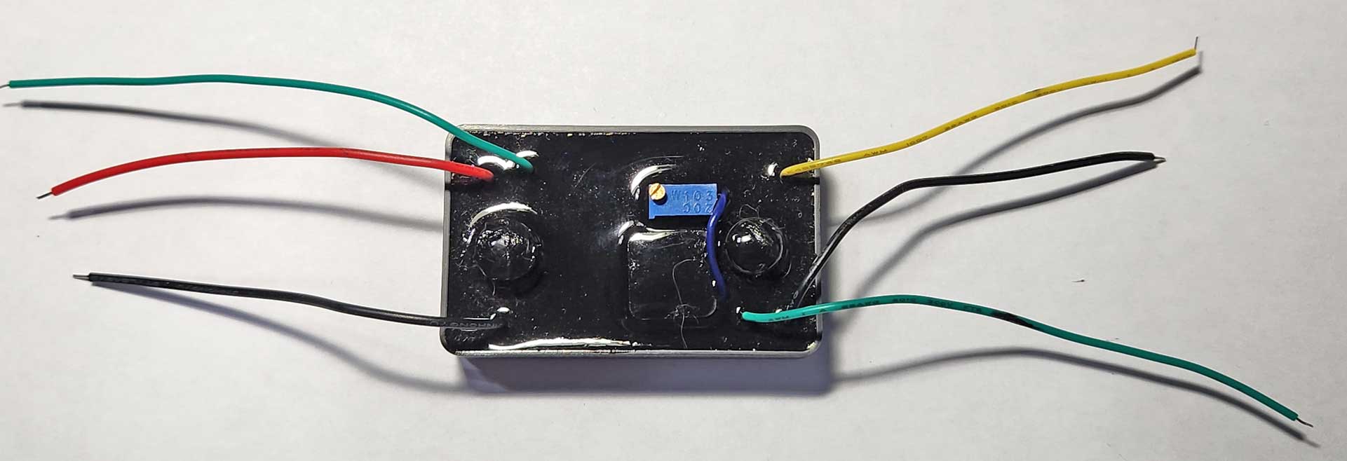 This power supply is sometimes referred as a "CTAS" in Widget Man literature. It can be used to provide a stabilized voltage level for the fan controller input, or for any 12v device (consuming under 1 amp). It's output is adjustable from 1.25 to 12.55 volts. A stabilized voltage level may not be needed for every car, but if you find that your car system voltage can fluctuate more than a few tenths of a volt when the alternator is under load, then it can make sense to provide a dead-even voltage level for better consistency. I used this power supply to provide a stable 12 volts to the fan controller. This way the controller would not experience any voltage fluctuations that might alter how it reads my engine temperature. What else can this be used for? A good example of using this power supply for something different is how I also later tried one for a Volvo 240 gauge cluster to replace a failed original 10v regulator. All 240 gauge clusters have a small 10v voltage regulator, which provides a regulated 10 volts to the temp and fuel gauges. I discovered the original regulator was not working as it should in a spare gauge cluster I was using for testing. This new power supply fixed that perfectly. More on that project is HERE in my Gauge Electrical Page. INSTALLATION DIAGRAM Here's a diagram below I made showing the use of the Widget Man fan controller for the JEEP brushless fan I installed. Plus I added the optional power supply. The optional/alternate universal temp sensor (which I decided to not use) is shown too in case you find a use. The temp sensor I used is the VDO Volvo factory temperature sender in my cylinder head. That turned out to be a good choice for my Volvo. 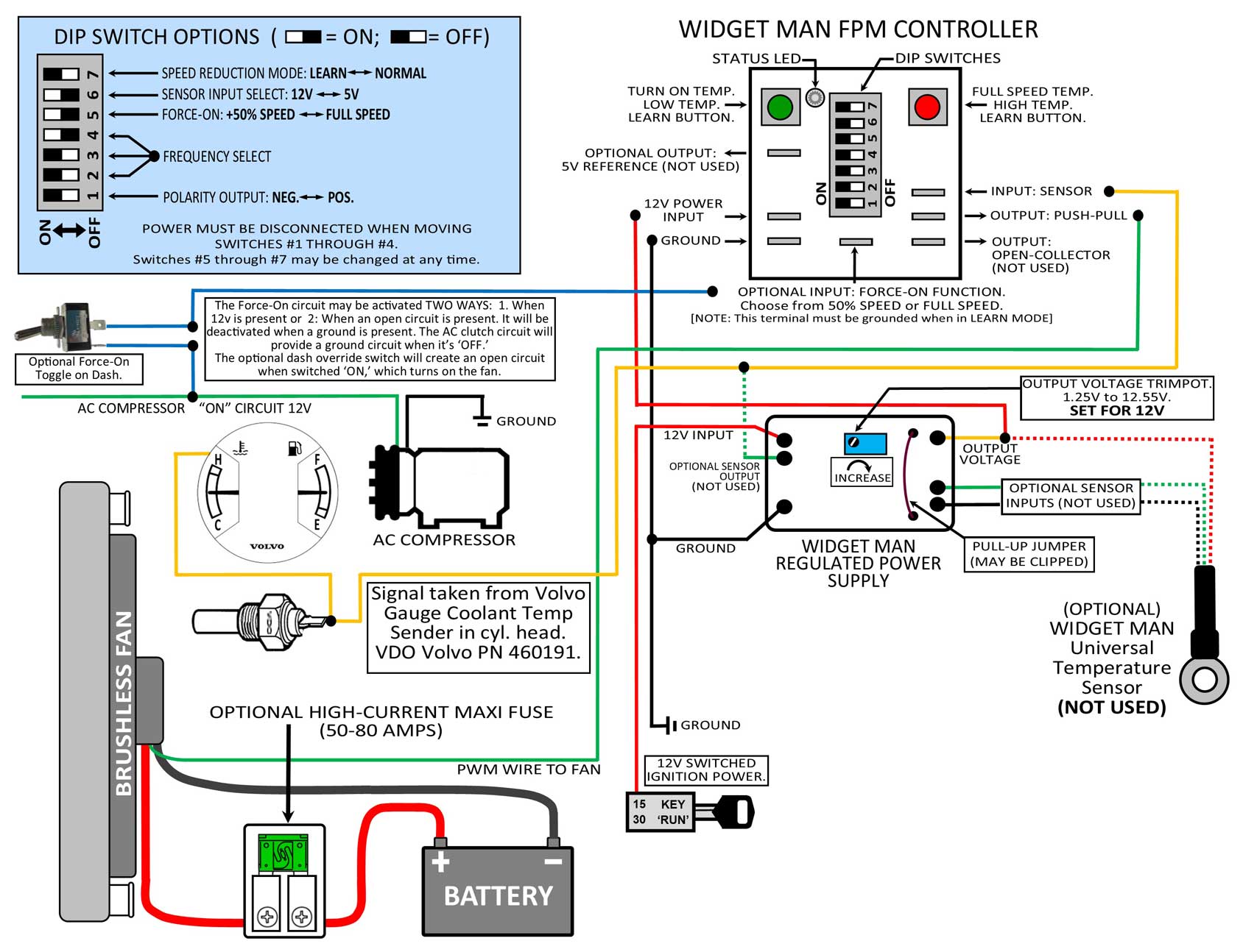
FORCE ON FUNCTION INFO The FORCE-ON function may be activated TWO WAYS. 1. When 12v is present at the Force-On input pin, or . . . 2. When an open circuit is present at the Force-On input pin. NOTE: Force-On function will always be DEACTIVATED when a GROUND is present at the Force-On pin.
OPTIONAL DASH OVERRIDE SWITCH The optional dash override switch wired as shown above will create an OPEN circuit to the Force-On pin when the switch is toggled ON. This will turn on the fan to the pre-set Force-On speed (use the dip switch option set for either 50% or Full Speed). Adding a switch like this will not force the fan to run at full speed, unless you have the Force-On dip switch set for Full Speed. If the Force-On dip switch is set for 50%, activating such a switch will elevate fan speed 50%. So for example, if the fan is already running at 50% based on temperature, flipping this switch would bring it up to 100%. This is the Volvo Coolant Temp Sender (for a 240 dash temp gauge). My plan was to use this sensor output to provide the temperature signal for the controller. 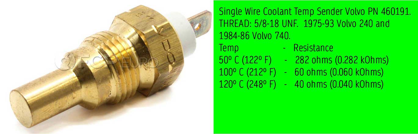
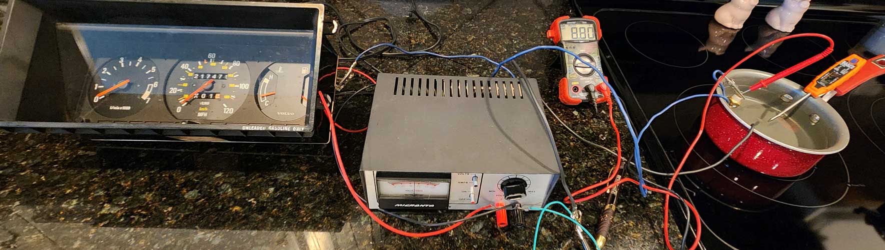
The below tests may be unnecessary for you, but I was curious about the range of readings coming from this COOLANT SENDER. Now that I've done these tests, you really don't need to if you decide to do an install like mine. You can just use this info if you like. This VOLTAGE test is not the same as an OHM test, like the Ohm readings shown above for the temp sender at certain temp readings. An Ohm test is for verifying sender calibration or to make sure your gauge reads right. These voltage tests below were done to find out the VOLTAGE values between this temp sender and the temp gauge. The temp gauge needle reacts to these voltage value changes. When the gauge receives MORE voltage, the needle goes DOWN (colder). Less voltage and it goes UP (hotter). This test was done on a kitchen counter using a 12 volt DC power supply and with the sender immersed in heated water. These values were also used to decide if I should use a 5v or a 12v sensor input setting on the Widget Man fan controller (this setting is selected with dip-switch 6). According to the manufacturer, the 5v setting is the best option because it provides higher resolution, but if the fan TURN-ON point and FULL-SPEED point that I would be choosing were found to be over 5v, then the 12v setting needed to be used. In this case, all values were over 5v, so I found that the 12v sensor setting was required when using this sender.
Side Note about some DEFECTIVE Used Volvo Temp Senders I found: My 240 uses the VDO Volvo sender (Volvo PN 460191). I had some used ones in my parts bin, which I was pretty sure worked when I got them or removed them years ago. But when I tested them with an Ohm meter, I couldn't get any readings. It was like the sensors weren't connected inside at all. I questioned my Ohm meter until tried a different meter. Then I ordered a new sender and that worked fine with my Ohm meters. Weird stuff. MORE Notes about this Coolant Temp Sender VDO/Volvo PN 460191. GENUINE VOLVO versus Aftermarket Senders. This sender image below represents the original factory calibration numbers. This should be consistent if you're using an original FACTORY VDO/Volvo part. You should know that if you purchase an FAE aftermarket sender (available from iPd or possibly other places), it's not calibrated quite the same. iPd mentions this in their FAE sensor description. On a later 240s with a functioning temperature compensation board in the gauge cluster, this may not be noticeable. But on an early 240 or on a car with a bypassed temperature compensation board, an FAE sender will usually put the needle HIGHER at operating temperature. I have found this to be VERY noticeable and VERY annoying on my 1984 240 . This is why I paid more for a new GENUINE VOLVO sender when I needed a new one for my car. HOWEVER, if you ever need to adjust or convert a sensor signal to work better for your needs, there's a device below that will do this for you to modify the sensor signal. INSTALLATION and PROGRAMMING of the Widget Man Brushless Fan Controller: Widget Man devices are sealed or potted, except for the dip switches on the fan controller. Those switches can be vulnerable to moisture, which could disable the controller. If the fan controller is to be placed in an engine bay, Widget Man recommended that the dip switches could be sealed with RTV sealer after the setup is complete. I didn't want to put sealer on the switches and I felt it would be a better idea to protect this by putting the parts in an enclosure. The fan controller and voltage regulator are attached to the inside bottom of this sealed project box with some double-sided tape. 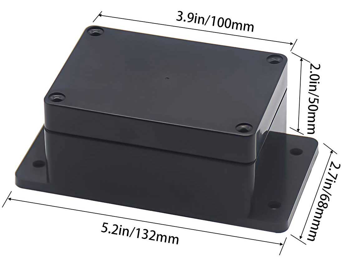 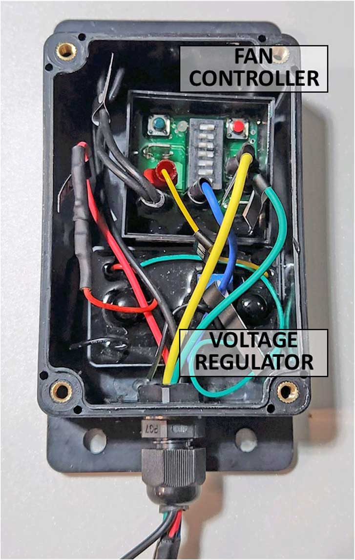 This sealed box is advertised as "waterproof." The top comes with a silicone o-ring gasket in a recessed channel, so it should do pretty well. Amazon sells this sealed project box and has others in a number of different sizes: amazon.com/dp/B07S6PKW2L The cable exit uses an inexpensive plastic gland nut that required a 7/16 inch drilled hole. I used the smallest size gland nut in this assortment: amazon.com/dp/B01GJ03AUQ Widget Man suggested that if I wanted to further protect the device, I could optionally smear some dielectric grease on the dip switches. I didn't do that either. TEMPERATURE RATING: These WM devices are rated for 225°F. It's best to place them in a less hot area in the engine bay, certainly not very close a hot exhaust or turbo. This controller produces very little heat on its own, so internal heat is not an issue. Widget Man Controller PROGRAMMING STEPS
Here are a couple pics showing the new controller in it's enclosure and mounted under the hood. 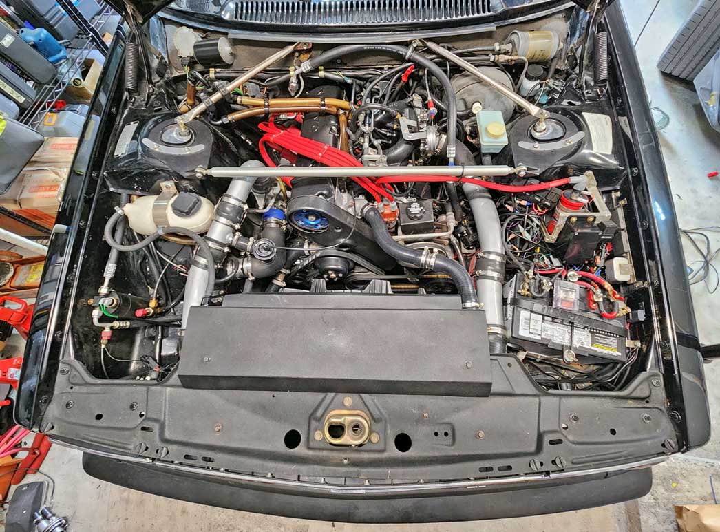 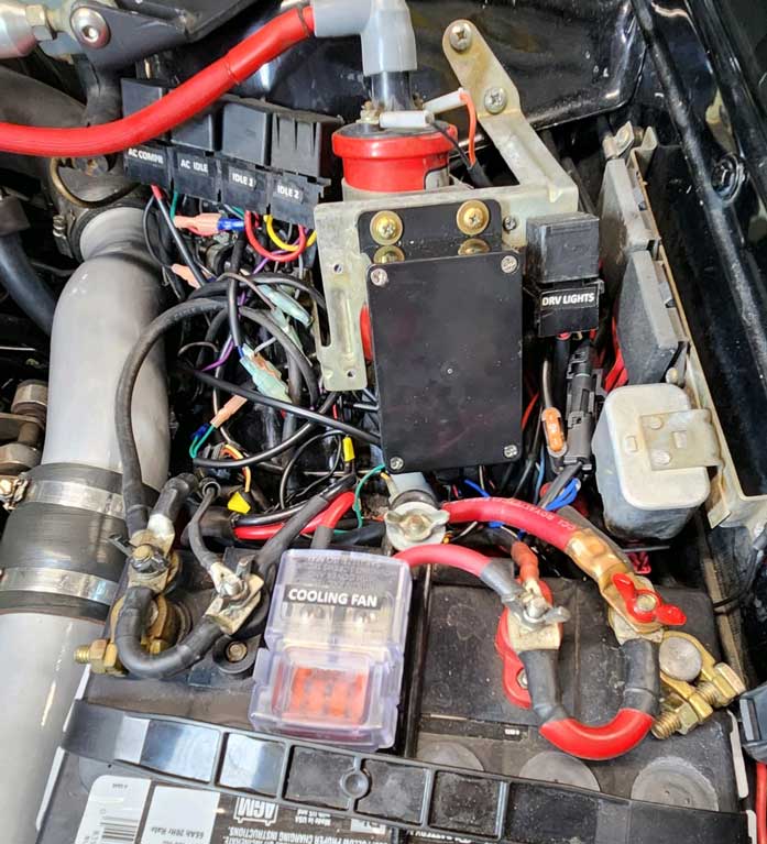
ROAD TRIP TESTING This controller was endurance tested with the new Jeep JK brushless fan on a 10-day 4000 mile cross-country trip in hot summer weather. It worked flawlessly. I have the fan speed set to keep my gauge temperature just below the middle ALWAYS. It stays there in any hot climate, with the AC on, and going up any grade. If you're curious about the coolant thermostat I'm using, it's a 92°C type (made to be fully open at 197°F).  Here are some OTHER devices from Widget Man which might come in handy for brushless fan conversions. This PWM Frequency / Polarity Changer may be useful for getting a 10Hz positive fan (Jeep or Mercedes for example) to work with a GM LS ECM, which needs a 100Hz negative frequency . This device lets you arbitrarily multiply or divide the Hertz rate and INVERT the polarity if needed. The only thing it won't do is adjust the OFF, ON, and MAX speed thresholds. https://gkgoodcheapparts.com/products/widget-man-pca-pwm-frequency-polarity-corrector 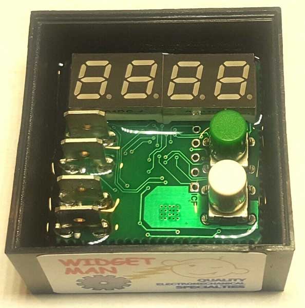 This Sine-to-Square Digital Signal Converter (SQC2) is an inexpensive assembly of transistors, which can invert the polarity or shift voltage levels on an existing PWM signal. https://gkgoodcheapparts.com/products/widget-man-sqc2-dual-step-up-step-down-sine-to-square-converter 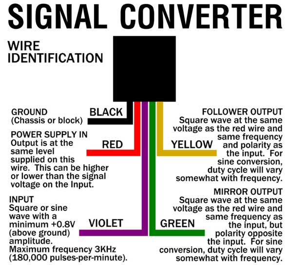 Widget Man UVM -- Universal Gauge / Voltage / TPS / APS Matcher. This device can be used to adjust, modify or convert just about any gauge sender or sensor signal to do just about anything you need. https://gkgoodcheapparts.com/products/widget-man-uvm-universal-gauge-voltage-tps-aps-matcher-upc-743407120871  Methods and Tools Used to Test Brushless Fans Keep in mind that most fan manufacturers are rating their advertised CFM tests to reflect a fan that is attached to a radiator, which in theory, restricts and reduces airflow by some amount. How is that restriction simulated? Can there be any consistency? Who knows? So testing a fan yourself might be the best way to find the truth or to satisfy your curiosity. These items below are what I've used to test fans. If you use something else and you want to share that info, feel free to email me: CONTACT PWM GENERATOR Most brushless fans cannot simply be connected to a battery to make them run for testing. This PWM signal generator below may be used to activate and run a brushless fan at any speed. This device generates a PWM signal only. It does not offer any temperature sensing options. There are up to FOUR wire connections, but only three are needed in most cases. The Power Input pin above is connected to BATTERY POWER. And GND is connected to BATTERY GROUND or CHASSIS GROUND. The PWM signal wire on the fan is then connected to the PWM slot. The PWM GND pin next to the PWM slot can be grounded also, but in most cases it doesn't need to be. It's a ground specifically for the PWM signal only. So if you have this device connected to the same battery as the fan, then the extra ground is not needed. In some lab settings or maybe some installations, the power and ground for a brushless motor may be from a different source than the power or ground going to this generator. In those cases the extra PWM GROUND would be needed. HERE'S A SIMPLE DIAGRAM SHOWING HOW TO USE A PWM GENERATOR IN MOST CASES If you have a fan which you're unsure of the frequency needed to make it run, it will usually be just fine to experiment with different frequencies or search through frequencies or frequency ranges to try to activate the fan. If you know what frequency the fan uses, then set the PWM generator for the fan. PWM Signal Generator. Price: $14.00 https://www.amazon.com/dp/B07P848DYQ Fan speed (RPM) testing has been done using an inexpensive hobby RC optical tachometer: Turnigy Micro Tachometer. This meter can be set to measure 2 to 9 blade fans and it's pointed at the fan blades when running. It was priced under $20.00. 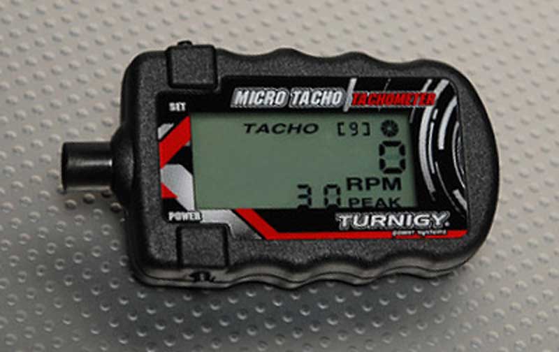 Amperage usage was measured using this Digital 0 to 100 Amp meter. Price: $15.00. amazon.com/DROK-Digital-Multimeter 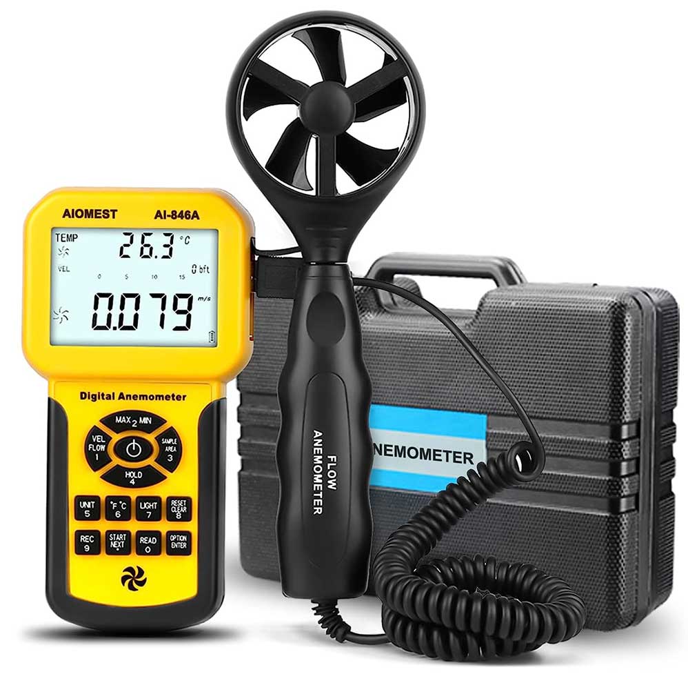 My CFM airflow testing was done using an Aiomest AN-846A anemometer. Price: $69.00 amazon.com/dp/B088QZ3689 This is the same airflow meter used by Fast Monty's Garage in this video: https://www.youtube.com/watch?v=pYkuNP1RnoM&t=26s. Similar fan area calculation methods that he used were used for my testing. If you watch the above Fast Monty's video, you'll probably have to pause and re-watch his math calculations a few times. It's a but much for a normal human brain. So I've placed the easier calculation steps I used below. Aiomest CFM Meter Calculation: Begin with the "actual" fan diameter: 18 inches, for example. I said "actual" diameter, which in my mind is the outer edge of the blade, not the outer diameter of a bigger plastic ring, which doesn't count. 1/2 of that diameter is the RADIUS: 18 x 0.5 = 9 inches radius. Then 9 ÷ 12 = 0.75. Then 0.75² (or 0.75 x 0.75) = 0.5625. Then 0.5625 x 3.14159 (Pi) = 1.767. 1.767 is the preliminary square feet (sq.ft.) area of an 18 inch fan. Now we must calculate the CENTER HUB area. I used 7.4 inches for the Jeep fan hub diameter. 1/2 of 7.4 = 3.7 inches radius. Then 3.7 ÷ 12 = 0.308. Then 0.308² (or 0.308 x 0.308) = 0.0948. Then 0.0948 x 3.14159 (Pi) = 0.2978. 0.2978 is the square feet (sq.ft.) area of the center hub. Now deduct the hub area from the fan area. 1.767 - 0.2978 = 1.469 (sq.ft.). 1.469 square feet is the final result for the fan area. So now you can set the meter on 'CFM' and enter your calculation. I entered the rounded number of 1.47 below for the FT ² setting. 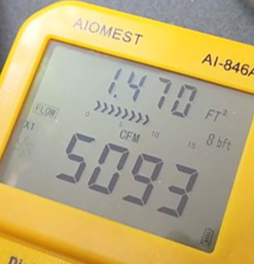 If you have any questions, comments or find any potential concerns, please send me an email: CONTACT. |
||||||||||||||||||||||||||||||||||||||||||||||||||||||||||||||||||||||||||||||||||||||||||||||||||||||||||||||||||||||||||||||||||||||||||||||||||||||||||||||||||||||||||||||||||||||||||||||||||||||||||||||||||||||||||||||||||||||||||||||||||||||||||||||||||||||||||||||||||||||||||||||||||||||||||||||||||||||||||||||||||||||||||||||||||||||||||||||||||||||||||||||||||||||||||||||||||||||
 Or you can try making a custom DIY shroud with VENT FLAPS. Here's a nice video on this. https://www.youtube.com/watch?v=wHOwYezz9Jw |
|
|
||||
| davebarton.com |
prancingmoose.com |
240turbo.com |
Special Emblems |
|
| Prancing
Moose Stickers |
Volvo
Stickers |
Body/Chassis/Engine
Labels |
240 MODS and FIXES Page | |
| Other Car Brand
Stickers |
Steering
Wheel Labels |
Center Cap Labels/Overlays |
Cool Volvo
Products |
|
| Grill Labels/Overlays |
Volvo Wire
Harnesses |
Conversion Harnesses |
Harness
Parts/Connectors |
|
| Volvo Relays |
Coil Repair
Harnesses |
240 Window
Scrapers |
740/940
Window Scrapers |
|
| Adjustable Voltage
Regulators |
Horn Buttons |
240 Odometer
Repair |
740 Odometer
Repair |
|
| Volvo Gauge
Faces |
740
Turbo/Boost Faces |
240 Black Door Vinyl |
850 Odometer
Repair |
|
| ALTERNATOR Page |
240 Power Mirrors - Switches |
240 Oil Cooler Page |
240 Fuse Panel Page |
|
| Group A
Racing 242 Turbo Page |
240 Hydraulic Clutch | Fuel Pump RELAY Page |
240 Headlight RELAY Page |
|
| Used Parts & Extra Stuff for sale |
CRIMPING Page |
240 Ignition Page |
240 Headlight Page |
|
| 240 Gauge Electrical Diagrams | 240 REAR END Page | Yoshifab Catch Can Install | 240 TAILLIGHT Page | |
| Side Marker
Lights Page |
Gentex Mirror Upgrade | Yoshifab Drain Tube Install | Modified 240 Favorites | |
| SoCal Salvage Yards | Unleaded Racing Fuel | B26FT Stroker | Dave's 245 Spec Page | |
| 240 SUSPENSION Page | 240 Lowering Page |
240 Windshield Page |
240 WIPER Page | |
| 240 BRAKES Page |
240 Dash Top Gauge Pod | Cadillac 4-Note Horn Install | 240 DYNAMAT Installation | |
| 4 Speed Fan
Controller |
Electric Cooling Fan
Page |
BRUSHLESS Cooling Fan Page |
Tropical Fan
Clutches |
|
| 240 AC Page | "KOMFORT BLINKER" Upgrade | T5 Trans Conversion Page | 240 Engine Mount Page | |
| 240 VIN Page | Stepper Idle Valve Page |
Vacuum Diagrams | 240 HOOD Page | |
| 240 Exhaust Page | 242 Power Vent Window Project |
EFI Volvo Pin Function Diagrams |
Favorite Links | |
| R-Sport
Apparel |
Prancing
Moose Apparel |
Volvo Meet Photo Albums | Texas Volvo Meets and Events | |
| Ordering Instructions | Policies | PAYMENTS Page |
Mojave Road Trail Map Page |
|
| Returns | Shipping | Shopping Cart Troubleshooting | Contact Us |
|

|
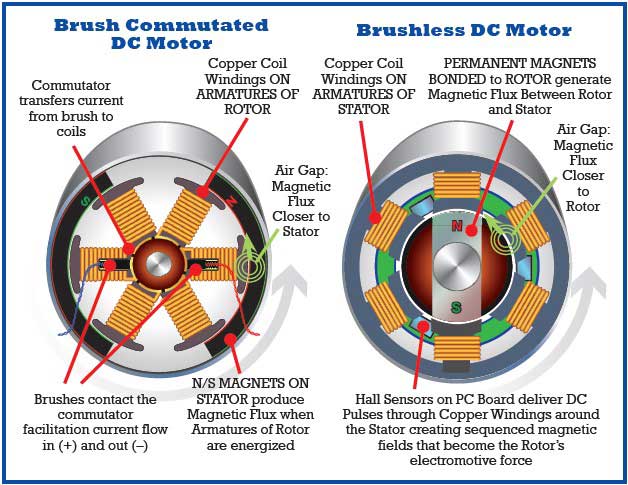
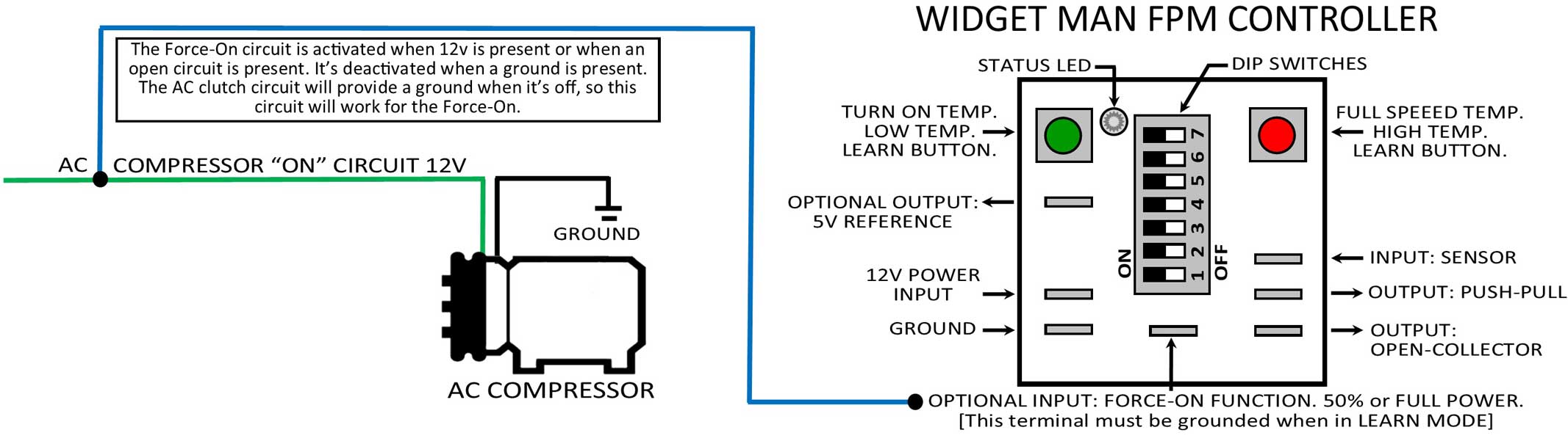