|
2 4 0 T U R B O . C O M D A V E ' S V O L V O P A G E
| ||||||||||||||||||||||||||||||||||||||||||||||||||
|
2 4 0 T U R B O . C O M D A V E ' S V O L V O P A G E
| ||||||||||||||||||||||||||||||||||||||||||||||||||
| This
page is being developed to explore and preserve some valuable
information related to high performance engine and cylinder head cooling for our Volvo B21, B23 and B230 engines. If you can help or if you have a comment or question, please email. CONTACT |
| Increased radiator capacity or not? Seems like a good place to start. or skip to next section: 1981 240 Turbo Introduction. The factory 240 cooling system was presumably designed by smart Volvo engineers. The 240 chassis supported 4 cylinder (B21, B23, B230) and 6 cylinder engines (B27, B28 V6 petrol and D24 inline 6 cyl. diesel). All 4 cylinder models got the standard radiator below. All 6 cylinder models got substantially larger radiators. 6 cylinder cars got larger radiators, because more powerful engines create more HEAT. 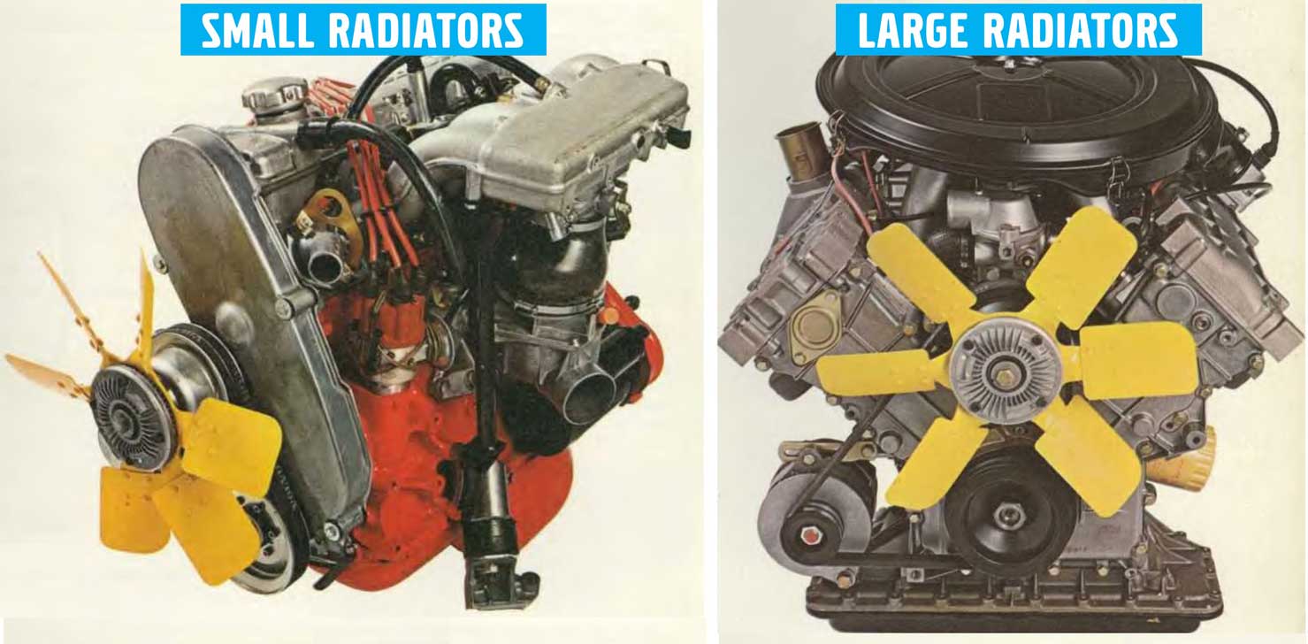 Here's the standard 240 4 cylinder radiator used from 1976 to 1993. Overall size: 579 x 444 x 44 mm (22.8 x 17.5 x 1.75 inches). Standard core size: 450 wide x 418 tall x 32 mm (17.7 x 16.5 x 1.25 inches). 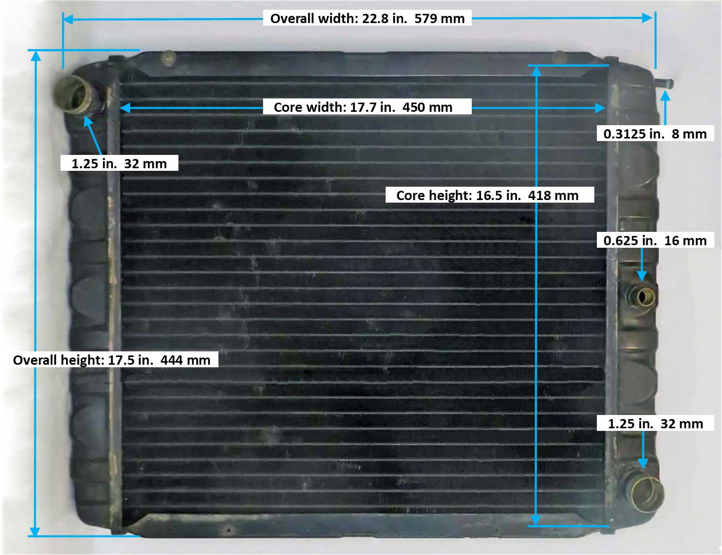 Volvo Part Numbers: Radiator for manual trans PN 1266050, 1336169. For auto trans PN 1266051, 1336170. A tropical version was available (changes not known). Tropical with manual trans PN 1266052, 1346994. Tropical with auto trans PN1266053, 1346839. Cooling fan 400 mm diameter PN 1317465. Thermostatic Fan clutch PN 1306259 (1266574, 1266669). HD Tropical fan clutch PN 1357433. The 240 4 cylinder standard radiator never changed through 1993. This is where, in my opinion, Volvo's design assumptions were WRONG. I'm highlighting this because, if you keep reading, you'll understand why I feel that Volvo did NOT do the right thing when using this radiator in ALL 240s, including the more powerful 240 Turbo, and in all 740 models, including 740 Turbos. I believe this radiator was undersized for the expectations of a 240, especially as it evolved with more power. So for many of you modified 240 owners, I feel this radiator is still undersized for almost any modified Volvo which produces more power than a stock non-turbo, especially if you also have air conditioning. Some of you won't agree with my opinion. I know because many 240 owners have voiced that disagreement over the years. That's OK. You're one of these people: "Volvo knew what they were doing." "I've never had overheating issues with a stock radiator." So I'm more of a cynic. My thoughts go more like this: "Volvo saved a LOT of money NOT having to change that small radiator for 20 years." If this little radiator was just right for every 240 and 740 with any engine, then why in 1992 did Volvo SUPERSIZE it for 940 non-turbos (32% bigger) and 940 Turbos (56% bigger)? I think Volvo was finally correcting a mistake. 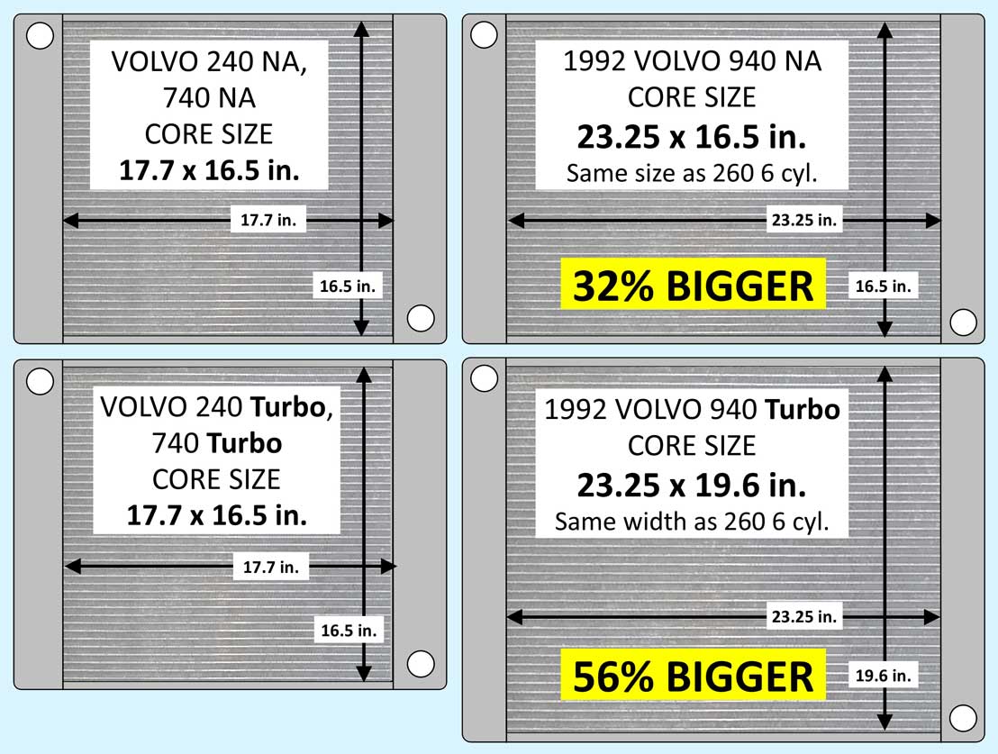 ORIGINAL COOLING TUBES I don't know for certain what size cooling tubes were used in these original radiators, but I can come close. The standard core thickness is listed as 32 mm (1.25 inches). This correlates to two rows of tubes, each up to a max of about 14 mm wide (0.55 inch).  UPGRADED NISSENS AFTERMARKET NISSENS used to offer an upgraded copper 3-row radiator for 240 or 740. Same overall dimensions, except thicker; about 2 inches thick (52 mm). 3-row radiators almost always use smaller cooling tubes than a 2-row, because often there isn't room to fit a 50% fatter radiator in a stock space. This can be an improvement if the tubes are large enough, but if not, then cooling improvement may be small or none. I think the Nissens tubes were about 12 mm wide (0.5 inch), which is depicted in the below image (this is my own photo, not a Nissens photo). I have more about the NISSENS 3-row below CLICK HERE. 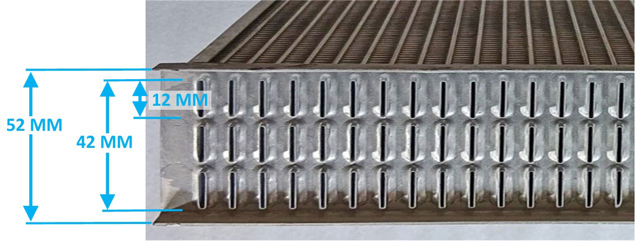 Size really matters when COOLING TUBES are considered. There will always be companies offering 3-row, 4-row, etc., radiators. I think MOST people assume more rows are always better. I DISAGREE. One claim is that more rows are better because more tubes can equal more surface area for cooling. That idea has some truth, but more rows also makes it harder for air to be efficient as it passes through a fat core. It can slow down the air and the air gets heated faster. The first row will get cooled pretty well, but the next rows not so much. It can be a delicate balance to promote good airflow AND still have good heat transfer. So you should study any radiator design closely before you buy and try to judge the good and the not-so-good. Don't fall for tempting 3-row fluff if they don't clearly list cooling tube sizes. A lot of manufacturers don't tell you this information. I suggest you insist on knowing that info. The cooling tube size can make so much difference. Not so much the number of rows. . 240 with 3 row Nissens radiator below. 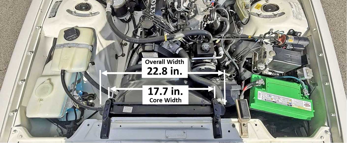 The 260 with B27 or B28 6 cylinder BELOW got a radiator that was much wider. Overall size: About 17.5 in. tall x 29.75 in. wide x 2 in. deep (445 x 755 x 52 mm). The core on this bigger radiator was about 16.5 in. tall x 23.25 in wide (419 x 590 mm). 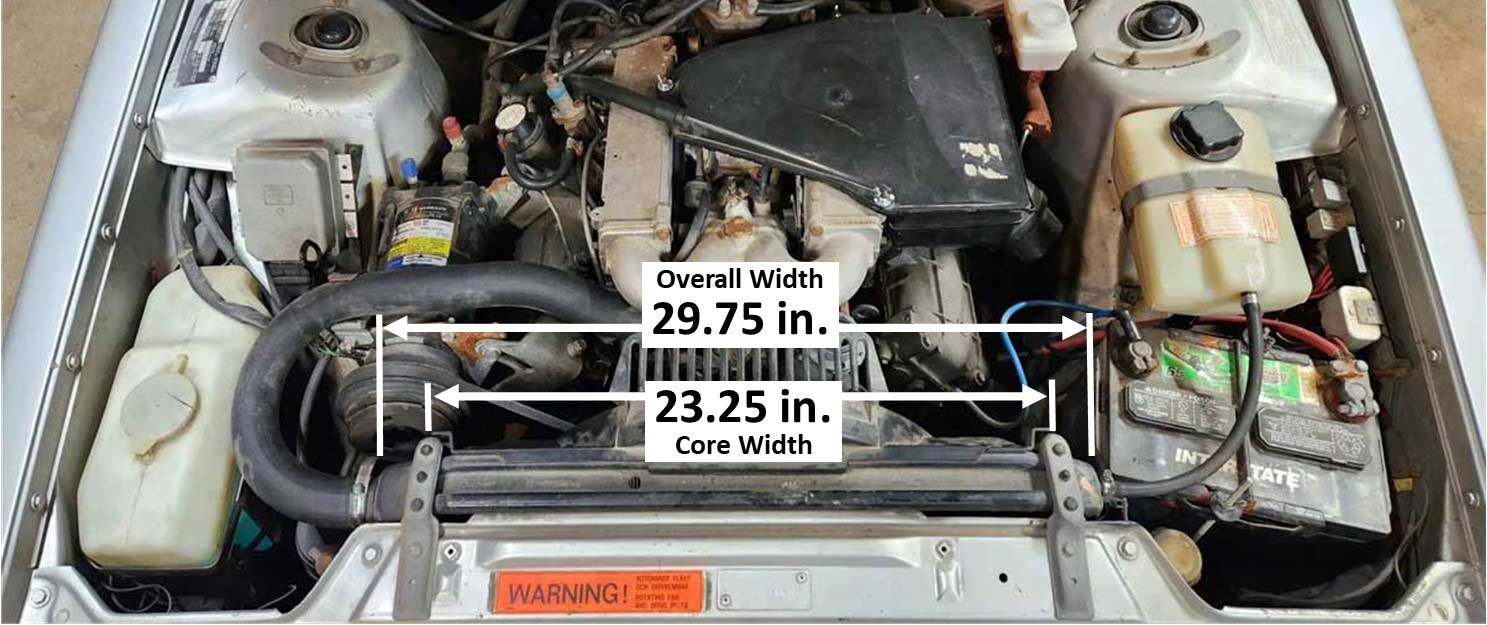 Part Numbers: 260 radiator PN 464025, 464924. Tropical version (unknown changes) PN 1274053, 1274055. The 260 radiator was not interchangeable to a 240. Volvo chose to INCREASE RADIATOR CORE AREA for 6 cylinder cars. From 292 square inches (1883 mm²) to 384 square inches (2477 mm²), a 32% increase. Why was this radiator bigger??? Did the smart engineers at Volvo calculate that the larger engine needed this because it made 32% more output? More output equals more heat, remember? Well let's see . . . Volvo rated the 1981 B28 6 cylinder at 153 ft.lbs torque, which comes to a 34% increase over the same year B21F with 114 ft.lbs torque. (I'm using torque instead of HP because I think it's a better representation of output). In 1981 Volvo introduced the 240 Turbo. or skip to next section: Intercooler Introduction.
The 240 Turbo (1981-85) came with the new B21ET (in Europe) and B21FT (in North America). In Volvo Manual TP30309, 1981 240 New Car Features, the B21F was listed with 107 HP and 114 ft.lbs. torque. The 1981 B21FT (without intercooler) was listed with 126 hp and 150 ft.lbs. torque (at 6 psi boost). This non-intercooled Turbo engine had a 32% increase in torque. (Again I'm using torque instead of HP because I think it's a better representation of output). So did Volvo make any cooling system improvements for the more powerful Turbo? Sadly, NO radiator upgrade was made. To their credit, Volvo did add an OIL COOLER to help offset higher oil temperatures from the oil cooled turbocharger. More info on oil coolers can be found in my OIL COOLER PAGE. 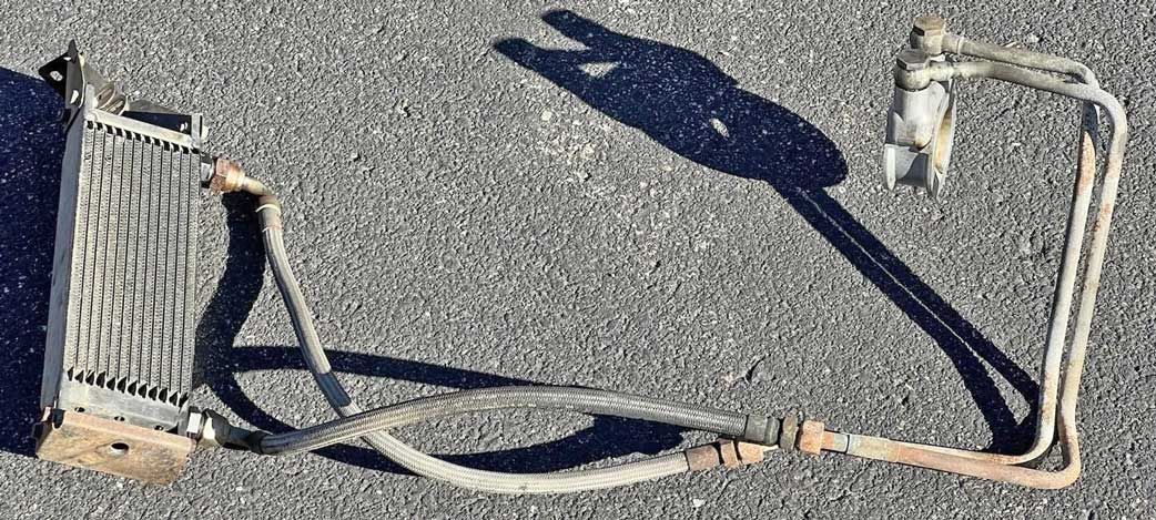 Do you think keeping the small radiator was an engineering decision or a cost saving decision? Possibly part of the decision was because Volvo anticipated the new upcoming 700 models would quickly take over as lead sellers, so the 240 could be retired ASAP. So maybe they didn't want to spend more development money on a car that was going away. The 240, however, did not go away so soon. Non-intercooled 240 Turbo below. 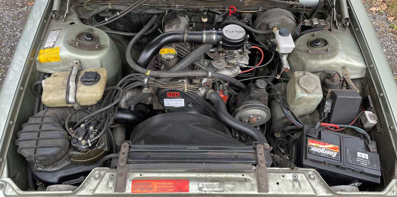 In my modest opinion, Volvo 100% should have increased radiator size for turbo cars. A larger radiator similar to the B28 size would have helped immensely. If they were not aware of this, they certainly should have been when the Turbo came out, and then it should have been even more obvious when the INTERCOOLER was conceived, which pushed B21FT output to 181 ft.lbs torque, a 59% increase over the B21F. Is my argument getting through?
Intercooled 240 Turbo below. 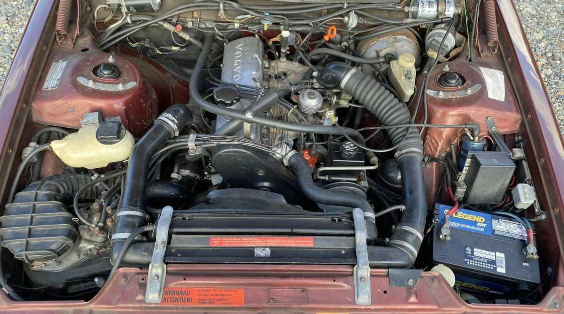 And now, by adding the INTERCOOLER, a NEW RESTRICTION had been placed in front of the radiator. More on this below.  Intercoolers were added with less than TWO years left of 240 Turbo production. So why did Volvo spend money on adding INTERCOOLERS for cars that were soon to be discontinued? or skip to next section: Experiments with a Larger Volvo Radiator. The north American imported 1981-1983 and early-1984 240 Turbo was not equipped with an intercooler from the factory. By 1982 Volvo had high expectations that the new 700 models would take over as the primary seller, so the 240 could be retired as soon as practical. Intercoolers were becoming more known and more popular, especially after the new 760 Turbo (with intercooler) was introduced (1982-83 in Europe. Mid-1984 in the U.S.). The 760 Turbo 1984 MSRP was $22,000 USD. The 240 Turbo was considerably less that a 700 models, but a lot more expensive than the base 240 DL or GL, so Volvo didn't sell nearly as many Turbos. About 950,000 240s were built from 1981 through 1985. It's estimated that only 30,000 to 40,000 of those were Turbos. The 1984 retail price for a 240 DL 2-door (manual trans) was $11,330. The 1984 240 Turbo 2-door (manual) was $16,540. But the sales figures for Turbos weren't the only thing that mattered. Volvo was getting a lot of great advertising value from having the well-performing 240 Turbo in their lineup. So it seems there was some pretty good justification for spending money on making 240 Turbos faster. FACTORY INTERCOOLERS ADDED. In September 1983, when the 1984 240 models were in production, Volvo made a marketing decision to add FACTORY INTERCOOLERS to all later production 1984 and 1985 cars coming to North America (set to begin in December 1983). This was great news for 240 Turbo customers and for dealers, except it would place a burden on sales of non-intercooled Turbos already built or still in dealer inventory. Volvo authorized a campaign to provide intercooler kits to Volvo dealers and to the public so the remaining cars could be retrofitted and a lot of cars were. The intercooler kit was retail priced at $595.00 plus three hours labor at the dealer rate. I believe this was a deeply discounted price already, considering the more than 25 components that came with the kit. KIT PHOTO HERE. 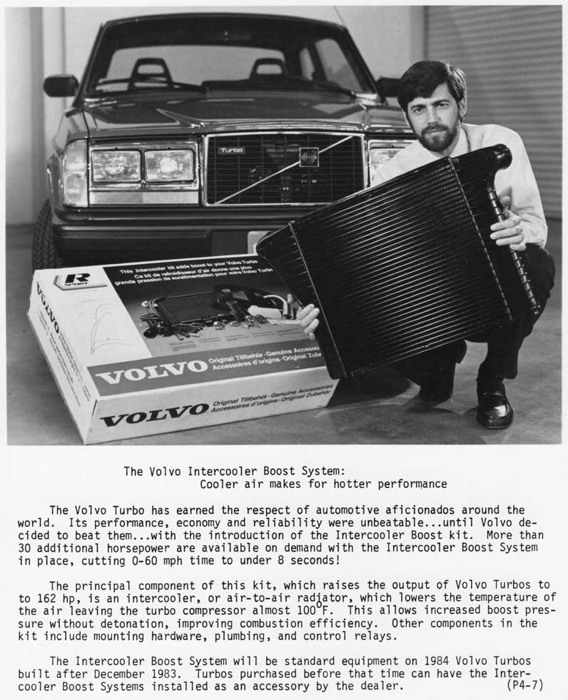 The intercooler was a great addition for performance, but were there any NEGATIVE EFFECTS? Did the new intercooler add a restriction to the radiator? It did, but I think the restrictive effect of an intercooler like this was small. These intercoolers were pretty open and free-flowing. This image below gives you a good close-up. The core design is Tube and Fin, which is common for factory intercoolers. 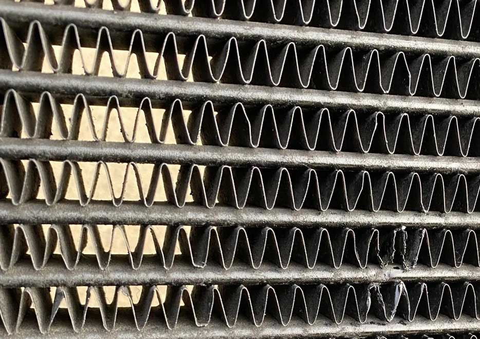 THERE'S A DIFFERENT PROBLEM. According to Volvo public relations info from late 1983, which promoted the newly introduced intercooler, the turbo boost in an intercooled 240 at 10 PSI would push compressed air to as high as 300°F (149°C). Volvo was proud to announce that their intercooler was capable of reducing that temperature by 100°F (38°C). That sounds great, but it means the intercooler can transmit a bunch of heat to the radiator; up to 200°F (93°C). Does that make it harder for the radiator to cool efficiently? Of course it does. I suppose this wasn't a huge concern, because most turbo cars weren't being driven at high boost for long periods at a time, but I know from experience that going up a long grade in these cars while in boost definitely could easily make the temp gauge steadily increase to an uncomfortable level. This was before Volvo added the temperature compensation boards in 1986 to fool drivers into seeing a lower gauge needle. Volvo made a compounded engineering mistake in my deeply held opinion. They had already made an error by continuing to supply the small radiator for more powerful B21FT engines. Many of us 240 Turbo owners were too easily fooled into accepting that Volvo engineers wouldn't make such a miscalculation. So we were desperately experimenting with band-aid fixes. So then Volvo added this intercooler, which WRAPPED AROUND the sides of the radiator, making it impossible to fit a wider radiator in the future. So then we hoped fatter radiators with more rows would be the cure. And if you think this more powerful intercooled Turbo was just fine in the cooler climates of Europe, you would be wrong. 240 Turbos in Europe were NEVER equipped with intercoolers from the factory (except for a very small number of Italian cars with B19ET motors). Eventually, much later, Volvo woke up from their nap and decided this radiator actually WAS too small. So in 1992, the 940 non-turbo got a much bigger radiator, 32% larger, and the 940 Turbo got a 56% larger radiator. Ok, so if there are still some of you who want to continue defending Volvo's small radiator, please email me and tell me why. And by 1984-85, there was also a campaign underway to offer upgrades to replace oil cooled turbos for water cooled versions, because many oil cooled versions were failing prematurely. The addition of a water cooled turbo certainly helped with turbo longevity, but it also placed more stress on the cooling system. Was this added stress significant? I think so. It would NOT have been such a big deal if bigger radiators had been a thing. More details found below in the Water Cooled Turbo Coolant Hose section. 240 factory intercooler PN 1317319 approximate dimensions. Made to fit a radiator with a maximum width of about 23 inches (584 mm). 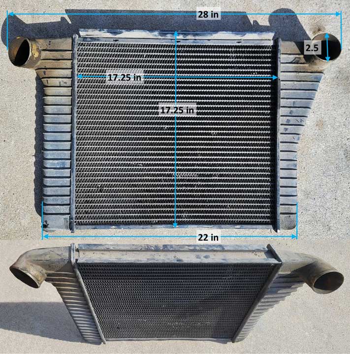 Intercooler Kit with Intercooler Boost System (IBS). If you're wondering what came with this kit, this is the most complete photo I have (except this 740 fan shroud is not correct). There were more than 25 pieces for everything needed, including the electronic parts for the IBS. The kit didn't actually come with the new intake air "cobra" tube. It came with a reinforcing hose to insert into the existing one so it wouldn't collapse. The tube had a potential to collapse under high vacuum or heavy acceleration. Please excuse the photo quality. I took this photo around 2000 and affordable digital cameras were brand new and very primitive. 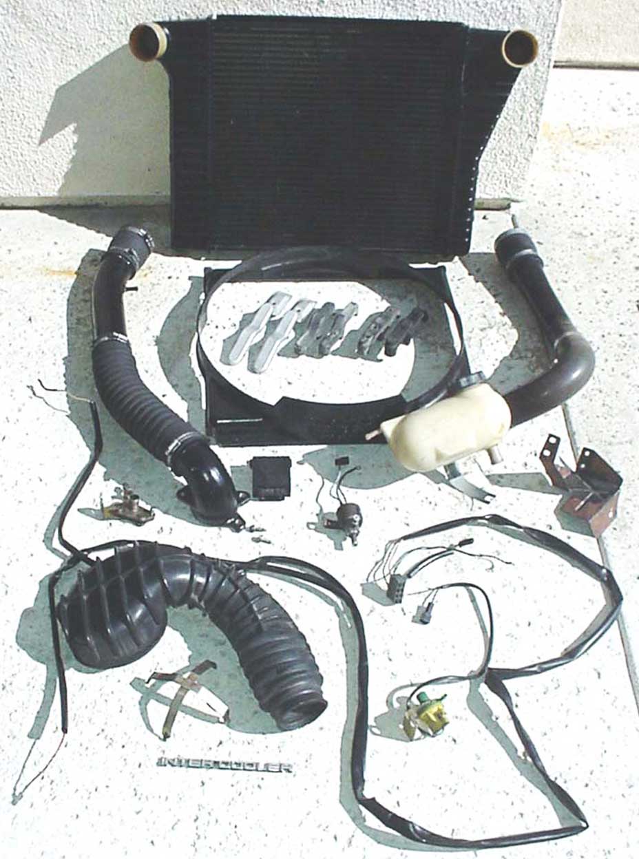 My own gradual Cooling System Evolution for my 240s. or skip to next section: Electric Fan Control. Back in 1997 I bought my first 240 Turbo (with AC). Living in a hot summer climate, it struggled to run cool in warm months. Of course I made some gradual modifications to increase power, which didn't help. I was new to the 240 Turbo and I clearly had a LOT to learn. I did a lot of experimenting to see if cooling could be improved while using the stock radiator. I was told to try things like Water Wetter, which did absolutely nothing. NISSENS I tried the "better" copper Nissens 3 row radiator. Overall size: 22.8 x 17.5 x 2 inches (579 x 445 x 50 mm). Same size as factory unit, except fatter. Core size: 17.7 x 16.5 x 2 inches (450 x 420 x 50 mm). 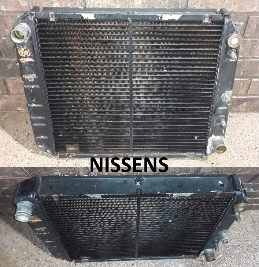 Everything depends on the size of the cooling tubes. I believe this 3-row radiator had about 12 mm (0.5 inch) cooling tubes, which is depicted in the below example image. The Nissens was a nice looking radiator. It looked like it could cool better, but it eventually proved to NOT be enough under hard conditions. And I know lots of you who bought Nissens units may have a different memory. I remember a lot of people back then who claimed to NEVER have overheating issues, even with a stock radiator. For a lot of these claims if you dug further you found out they often meant "under normal driving conditions." Nissens sold HUGE numbers of these 3-rows, so there were obviously a lot of people dissatisfied with the stock radiator. Here's a useful article comparing 2-row radiators to 3-row or 4-row. https://www.speedwaymotors.com/the-toolbox/mythbusting-1-row-vs-2-row-vs-3-row-radiator-cores-explained/145787 Here's a pretty basic RADIATOR CORE SIZE CALCULATOR that might help for comparing sizes or by adding variables. TIP: If you want results for a car stopped, enter ZERO highway speed. May not be very realistic, so I'll call it mostly for entertainment use. But I thought I'd share it. https://onlinetoolkit.co/car-radiator-sizing-calculator/ At some point I also replaced the fan clutch with a higher viscosity Tropical Fan Clutch. That did help some also, but it was still not enough under hard use in hot weather. Maybe you're wondering if my hopes and expectations were unreasonable. I didn't care. I wasn't going to give up. Why couldn't I have a car that could drive up a long steep grade in the hot desert with my AC on, and with a temp gauge that stayed where it should? The overwhelming consensus of every Volvo owner around was that was never going to be reality. More on Tropical Fan Clutches can be found in my Fan Clutch Page HERE. Electric Fan Control or skip to next section: Ron Davis Radiator. An important note about Belt Driven Fans First. As most of you already know, every Volvo 240 and 740 using the small 240 radiator came with a belt driven clutch fan. There's a lot of info written by me and lots of others about eliminating that mechanical fan and installing a powerful electric fan. What most of you almost never hear is that the mechanical fan is usually pretty adequate for most cooling needs, even with a modified or boosted engine and if a PROPERLY SIZED RADIATOR (this means WIDER) is used, along with a proper fan shroud of course, then moving to an electric primary fan can often be avoided if you like. The primary failure in Volvo's cooling system designs were that small 240 radiator, not in the 16 inch mechanical clutch fan. Volvo 2-Speed Cooling Fan Relay PN 9442934. I'm highlighting this 2-speed relay because so many people are still using it. It's ok if you are, but there are MUCH BETTER control systems available. Some of this is also discussed in some of my other pages, like at https://www.240turbo.com/ElectricCoolingFans.html#volvo2speedrelay, 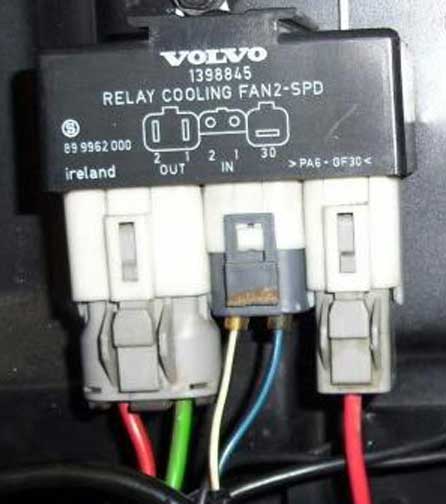 This 2-circuit relay was supplied by Volvo in various 1992 and later models with electric fans, including the 740, 850, 940, 960, C70, S70, V70, S90, and V90. 2-SPEED RELAY WIRING DIAGRAM 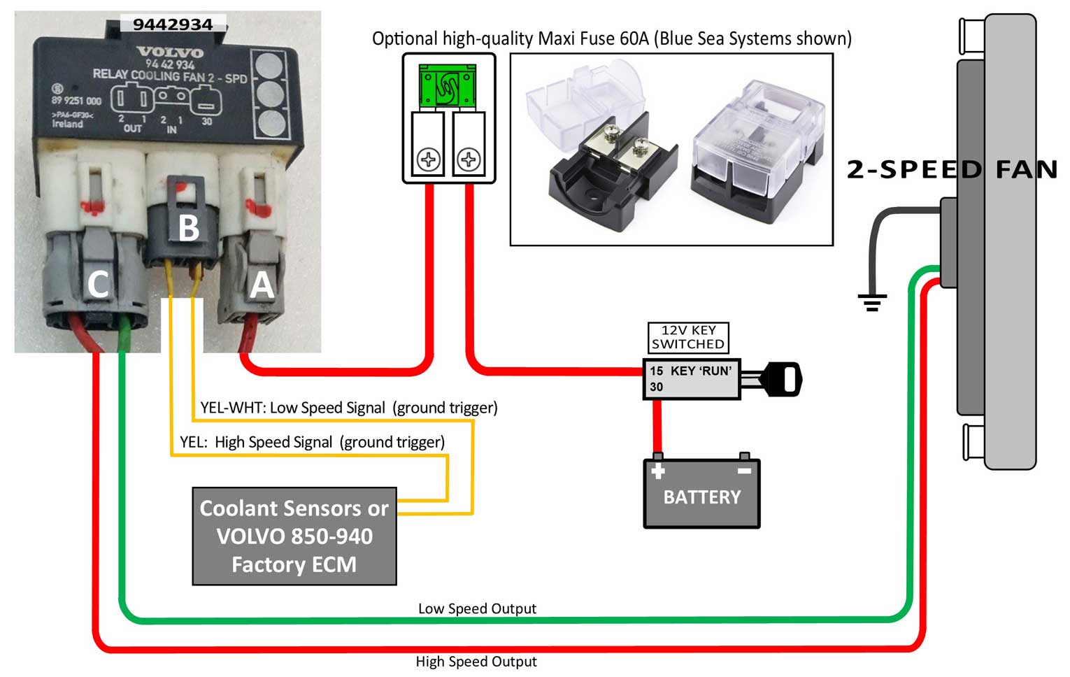 The wiring diagram for this relay is pretty simple, but if you're using this to retrofit into a modified car and you want more advanced fan AND temperature control, there are MUCH BETTER solutions now, which are detailed below. One Better Option: Autocoolguy https://www.autocoolguy.com/ His web page isn't modern, but his adjustable PWM DC fan controllers are very nice. In 2018 I began using a 125 amp version of the Autocoolguy PWM controller for a large brushed DC fan. It worked exceptionally well and it allowed my fan to have a true soft start and it could then run at lower speeds (or any speed needed) to maintain your user-set temperature. Plus it had a user adjustable AC override that was very welcomed. It also had an input for a full-speed override, which can be controlled by a switch on the dash. I posted a more details in my page at https://www.240turbo.com/ElectricCoolingFans.html#autocoolguy. Autocoolguy HF-125 Review - Upgraded Controller https://www.youtube.com/watch?v=u7yaRceJ2hM My Autocoolguy diagram from 2018. If you're using a 2-speed fan, the best way for a controller like this is to use the high speed circuit only.  Another Better Option: Widget Man https://gkgoodcheapparts.com/ When I chose a new fan control system for my brushless fan setup in 2022, I turned to Widget Man. The controller I used has been working flawlessly since 2022. More details here about my selection and setup in my Brushless Fan Page. For those of you using a 2-Speed BRUSHED DC cooling fan, Widget Man offers a very nice controller called the FDM2. It will function for a 1 speed or 2 speed fan and it will allow precisely TUNED ON-OFF temperature adjustments using just about any temperature sensor or sender, even your factory coolant gauge sender in your cylinder head (which is what I use). https://gkgoodcheapparts.com/products/widget-man-fdm2-self-learning-dc-fan-relay-controller  Here's a suggested wiring diagram. 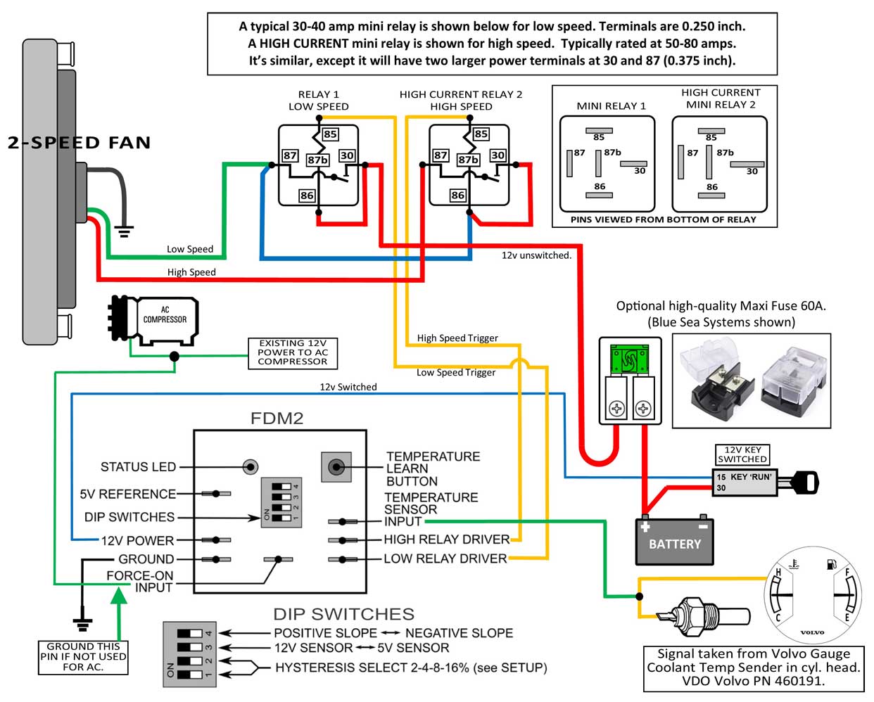 If you're using the standard 240 temperature sender shown above, then Dip Switch 3 should be set to 12V. If you need more info on that, click here: https://www.240turbo.com/BrushlessFans.html#tempsendertest Widget Man After Run Timer-Controller. New for 2026 (with more info coming later), the Widget Man FPMR is purpose-designed to work with Widget Man fan or pump controllers, or it can work with many other controllers or it can drive relays. This controller output has an 11.5V precision voltage regulator with 1 amp capacity, enough current to power multiple FPM's, multiple relays, or any mix your setup may require. The timer can run from 0~5 minutes, and there's an optional temperature input which can prevent after-run when it isn't necessary. The temperature sensor can be separate or shared with an FPM or FDM2, depending on your needs. For instance, this device can easily respond to intercooler temperature while the FPM / FDM2 responds to coolant temp. The FPMR “learns and remembers” your chosen cutoff temperature the same way as the FPM / FDM2, so adding temperature to the timer is as simple as 2 button presses. The FPMR can also run with no timer and only temperature if desired, giving you total latitude in meeting the needs of your setup. 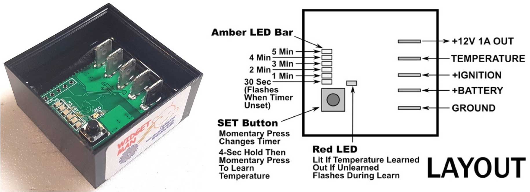 An upgrade for my 240: My first all aluminum performance radiator. or skip to next section: 940 Radiator. In about 2000 I built a 2.6 liter stroked engine based on a B23FT. It produced 326 ft.lbs. of torque. It needed more cooling. And through all this, I was still hearing from Volvo owners all over who were saying, "I don't have any cooling issues with MY stock radiator." Then someone with a brain suggested an all aluminum radiator from Ron Davis Radiators in Arizona. 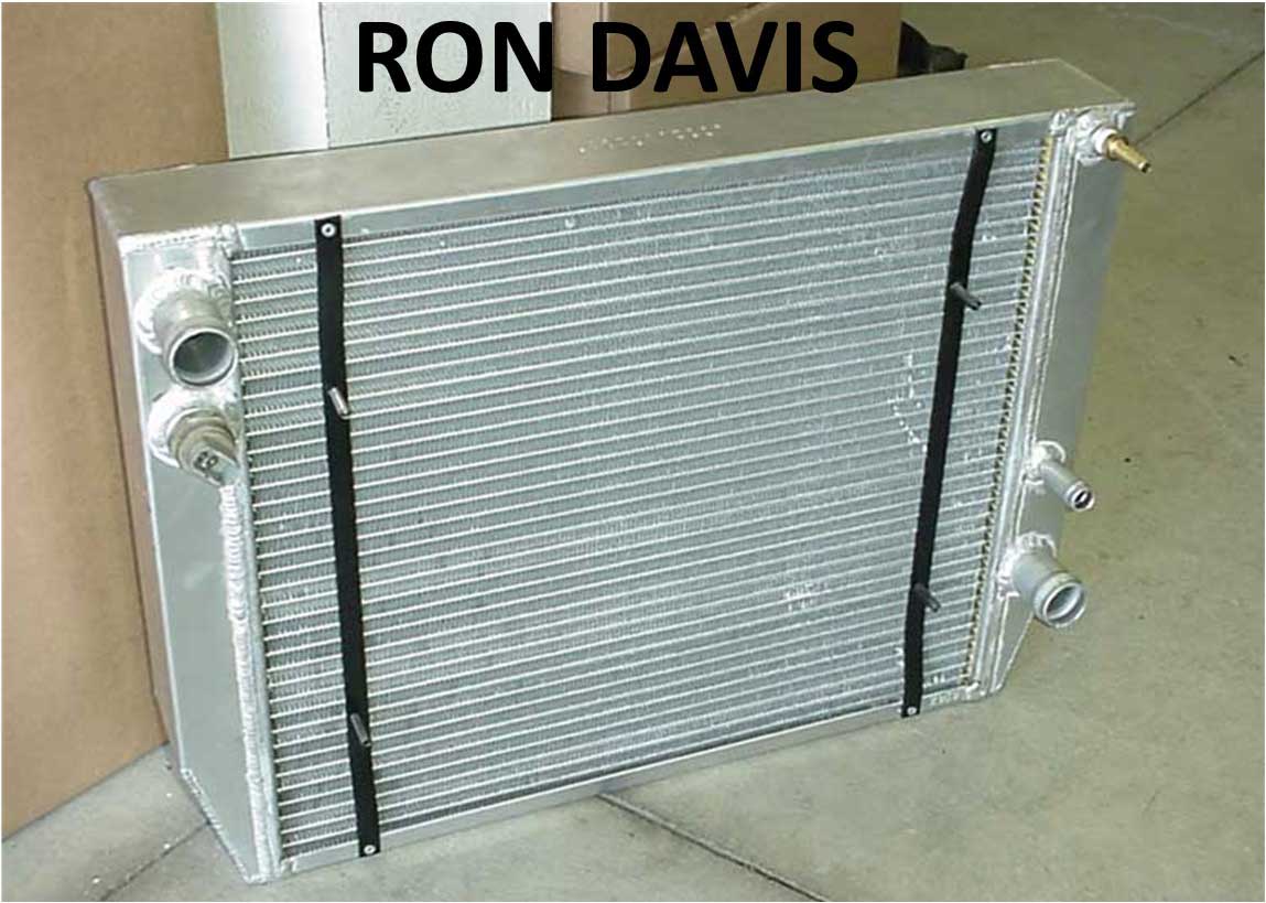 Ron Davis offered high quality, high performance radiators with two rows of large 1 inch wide cooling tubes. That sounded a LOT better than a small tube 3 row Nissens. So I bought one of these radiators in a similar height and width as a factory 240 radiator. This is a depiction of how two 1 inch cooling tubes look in a radiator like this. 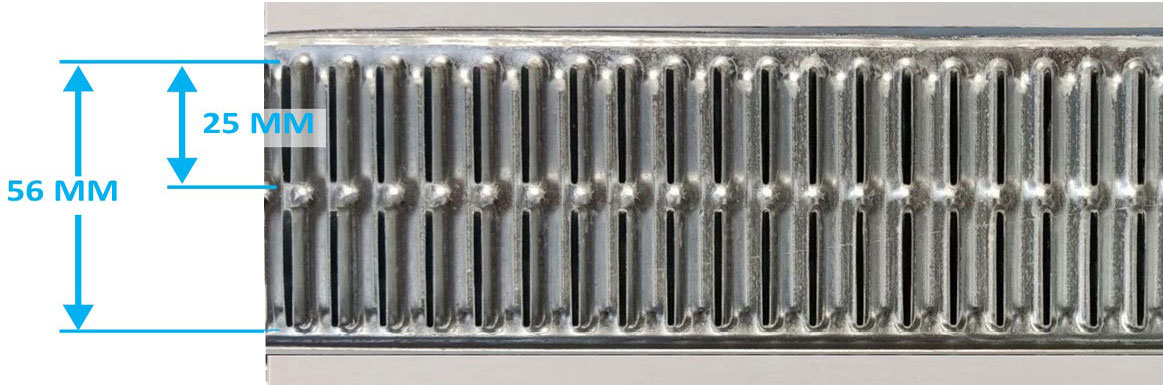 I will say that Ron Davis made really, really high quality aluminum radiators. They were not cheap. And they would be even more expensive if a custom one was made. I saved a lot of money by selecting a Chevy style radiator from their Stock Car page. They had a listing of different standard sizes in that page. The one I bought was considered UNIVERSAL. It was about $350 back in 2000. That sounds pretty reasonable now. The Ron Davis radiator was a good improvement over the Nissens and it did end most overheating during most driving conditions. I had no complaints about the build quality and I would certainly consider them again (Actually I did consider them later. Keep reading). But looking back, there were still things that bothered me, like going up grades and still nervously watching the temp gauge rise. Everyone said that was normal for a 240 and I should learn to live with it. I did that for years. At one point, I thought the large intercooler covering the entire front of the radiator was reducing airflow too much and making it work too hard, so I had a section on the bottom of the intercooler cut off so more air could go under it. I don't think that helped at all. It certainly didn't fix things. This photo below is from 2000. 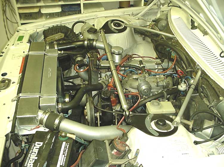 This custom Spearco intercooler was built using the approximate dimensions of a factory intercooler. It used Bar and Plate construction instead of Tube and Fin. It was 28 inches wide at the top, 22 inches wide at the bottom, 17 inches tall, and 3 1/2 inches thick. 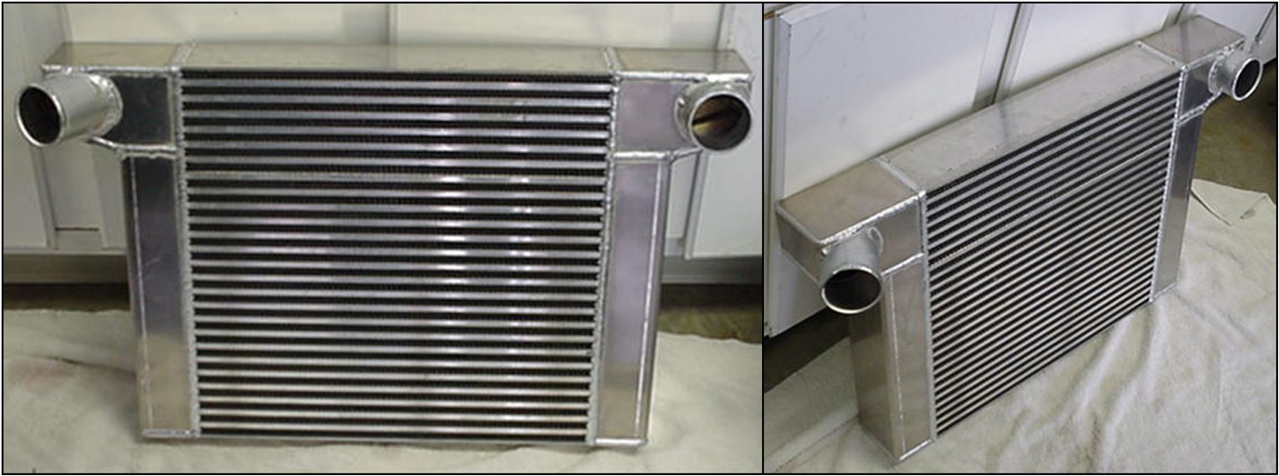 COOLING TESTS. If you're wondering how much charge cooling improvement can come from an intercooler like this, I did some temperature reduction tests, which you can see at https://www.240turbo.com/specsheet245.html#intercooler. Spoiler alert: Testing was at 15 psi boost during a steady climb up a very long steep grade at 90 MPH for a number of miles. With an ambient temp of 70° F (21° C), I allowed the intercooler inlet temp to peak at 340° F (171° C) and the outlet stabilized at 77° F (25° C). This was really good performance. I logged a maximum temperature reduction of 263° F (128° C). You'll see coming up I later bought a WIDER aluminum radiator in 2012. A wider radiator meant the really nice intercooler above could no longer be used. And I didn't go with Ron Davis for the next radiator. Why not? I did call them first and spoke to a shop manager. They used to list prices in their site, but all prices were missing in 2012. So I called to ask about buying a wider 26 x 16 inch universal Stock Car Chevy style. I was told the new price was $750. This was twice as much as a similar universal type from any other manufacturer. I asked the manager what had changed. He told me Ron was very busy selling a lot of very high-end custom radiators for a lot of really big-dollar hot rod projects and he felt he was worth a lot more than anyone else. During my years of cooling system trials I experimented with a number of electric primary fans (these are all shown in my Electric Cooling Fan Page). Some fans seemed to help if they were really big, but it never reached much satisfaction until I eventually began using a very large fan and shroud from a Ford Thunderbird SC that I found at a salvage yard. I eventually realized I was trying to force an enormous amount of air through a small radiator and I concluded that was not a correct way to do things. I needed to do what Volvo did in 1992. I needed to move up to a larger, WIDER radiator. I had learned an UNDER-SIZED radiator with a HUGE FAN was not the answer. If there was room for more radiator (and there was) then that's what I was going to do. It's time for a video. This will show how a custom aluminum radiator is built. https://www.youtube.com/watch?v=c8kq0-3PCJY Experiments (not mine) with a Larger Volvo (940 non-turbo) Radiator. or skip to next section: Northern Radiator.
This info below will discuss some past experiments (not mine) using a larger factory Volvo 940 radiator in a 240. BELOW: Here's how the WIDER radiator looks in the 1992 and later 940 non-turbo. 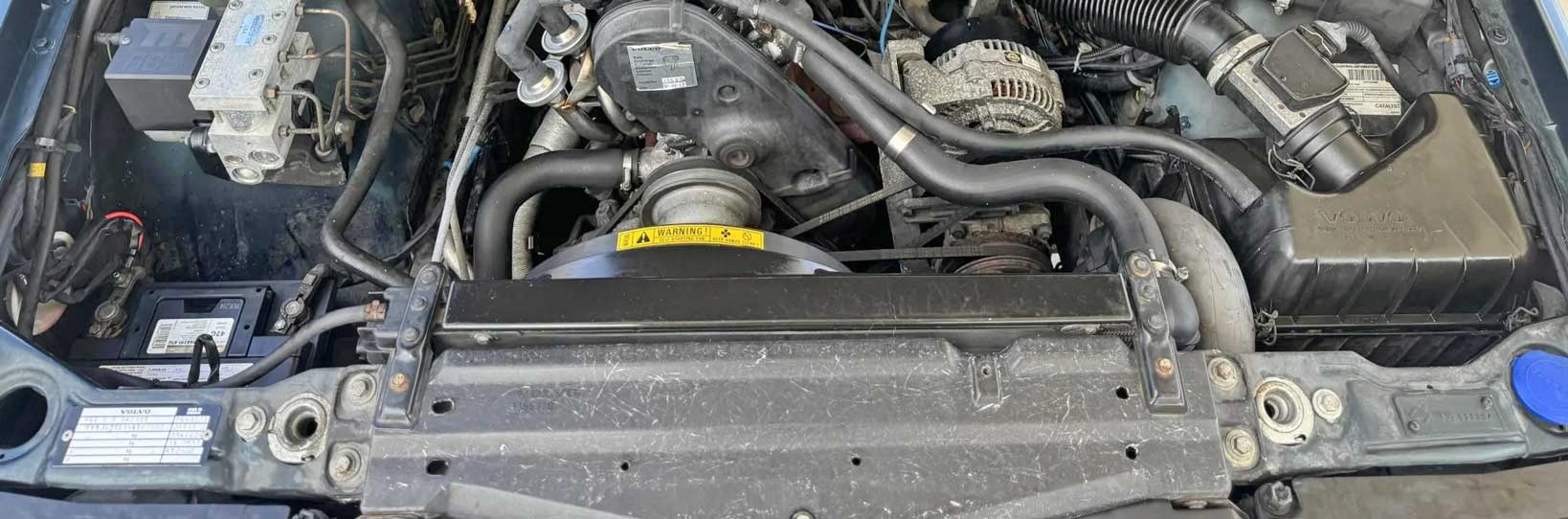 This 940 non-turbo radiator was highlighted in the below TB discussion threads by user towerymt, who installed one in his 240. It's Volvo PN 3547155 (normally fits a 1992 740 non-turbo with electric fan, or 1992-95 940 non-turbo with electric fan). It's 5 inches wider than a 240 radiator and about 1 inch taller. Full dimensions below. The 940 radiator shown below and in the thread was a Nissens (aftermarket). The top clearly sits up a bit higher above the radiator support, but he said the hood would still close. This 940 non-turbo radiator should not be confused with the 940 TURBO radiator (PN 3547146, 8603853), which is 80 mm (3.15 in.) taller (with a 499 mm core height) and will not fit in a 240, unless maybe you don't need your hood. https://turbobricks.com/index.php?threads/volvo-radiator-sizes.211006/ This radiator installation was originally highlighted in March 2010 in Post 292 of his car build thread: https://turbobricks.com/index.php?threads/1987-244-dl-autocrosser.127832/page-15#post-3010144 The reason a larger radiator like this works so well in a 240 is simple. MORE SURFACE AREA is always better than a small radiator with more rows or bigger fans. So Volvo used this radiator for a non-turbo B230F. Can anyone still believe Volvo was correct to use the smaller radiator in the 240 Turbo? 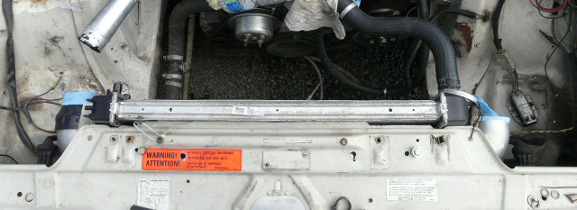 You cannot use a standard 240 intercooler with this wide radiator. There are other options. 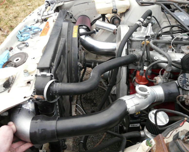 Dimensions for Volvo PN 3547155, 1992 740 non-turbo, 1992-95 940 non-turbo. 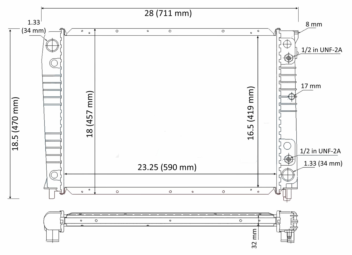 The core has 384 square inches (2477 mm²) of surface area. Coincidentally, this is the SAME surface area as the 260 radiator. If compared to an original 240 radiator with 292 square inches (1883 mm²), this 940 radiator has a 32% increase. Here's another oversized radiator that can be considered for a 240. or skip to next section: More Radiator Resources. This is made by Northern Radiator and is available from STS Machining in Oregon. Overall Dimensions: 27.125 x 16.5 x 3.125 (689 x 419 x 79 mm). Core with about 349 cu.in., about 20% larger surface area than stock. The description says it has 1-row, but I don't think it does. I've never heard of a 1-row with a depth of 3.125 inches, especially from Northern. So I think it may be 2 rows with 1 inch or 1.25 inch tubes. And not all of the dimensions below have been verified. I've asked, but the supplier so far has not responded. https://www.stsmachininginc.com/products/northern-radiator-ls-swap-or-redblock-240-740-940-series 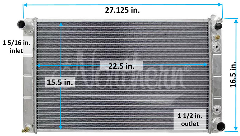 do88 WC-250 This is a replacement radiator that do88 offers for a 240 or 740. I has the same general dimensions as a stock 240 radiator. It's advertised as a 2 row with a 50 mm (2 inch) thick core, advertised with 57% more core volume than stock, but I don't think you can equate that to compare to a wider radiator without more info. Dimensions are not listed by do88. https://www.do88performance.com/en/artiklar/volvo-240-740-940-manual-75-98-radiator.html https://www.ipdusa.com/products/23786/777/1981-Volvo-240-Non-Turbo-Aluminum-Radiator-240-740-760-940-Manual-Transmission-Do88-WC250 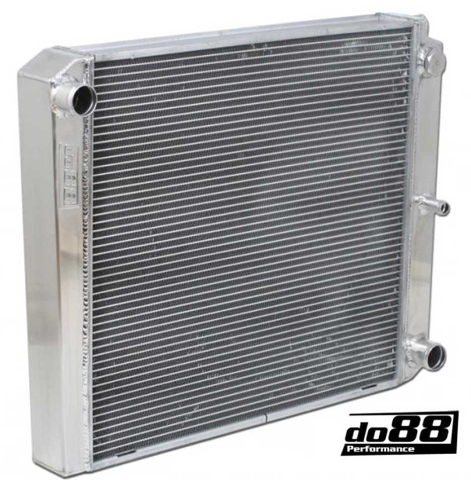 Installation instructions: https://www.do88.se/bilder/artiklar/pdf/WC-250.pdf More Large Radiator Resources. or skip to the next section: Time for a WIDER Radiator. I'll add more here eventually as I find more potential choices. If you have suggestions, CONTACT. During my research I came across some videos about Cold Case Radiators. It seems they're also offering 2 row radiators with 1.25 inch tubes. I haven't investigated them deeply, but this company may be an alternative if you can find a radiator in a size you can use. A quick look through their available sizes in their site found very few in the 16 to 17.5 inch tall range. Their line up normally caters to vintage domestic cars that almost all use 19 inch tall radiators, so it's very limited. And you might be tempted to look into Champion Radiators, because they advertise 3-row aluminum radiators. But judging by the comparison image below, which I took from the below video, I would definitely not. The Champion 3-row core is smaller in thickness than the Cold Case 2-row. So Champion must be using really small tubes. Advertising "3 rows" can sound nice until you look closer. This guy found the 2-row Cold Case cooled better. Don't get fooled. VIDEO: Cold Case CHC11 vs Champion 3 row Radiator: https://www.youtube.com/watch?v=5YDu51g9fzY 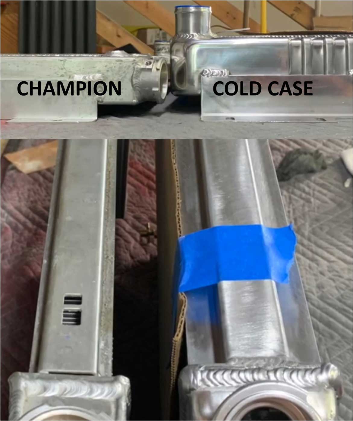 It was time for a WIDER Radiator for my 240. or skip to next section: Group A Intercooler.
Long before me, Volvo Group A racing teams figured out what was needed. A few Group A Volvo 240 Turbos were built by privateers for the 1983 European Touring Car season. There were serious problems with the Volvo radiator. Volvo engineer Göran Sällström was involved in his spare time with some other Volvo employees in building one of the early Group A 240s. He got help from a cooling specialist in Gothenburg. The result was a much larger and more satisfying radiator. It not easy to see the radiator in most Group A engine photos, but you'll see below. This photo is an RAS Sport Volvo 240. 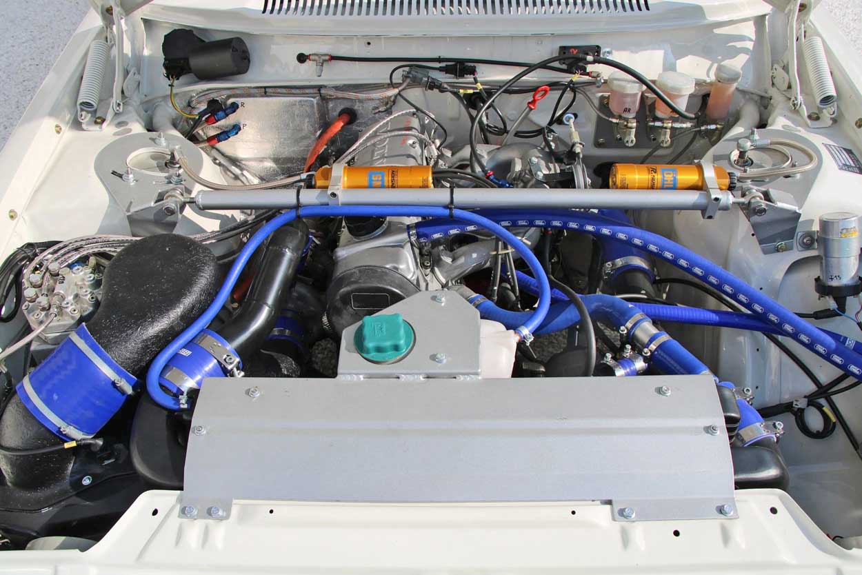 The best photo I've seen of a larger Group A radiator behind the big Group A intercooler is this one BELOW from Björn Ohlson's 240 Grupp-A page https://240grupp-a.se/kylning/. According to Björn's page, larger radiators were sought out by racing teams in 1984 after they found the Volvo radiator to be useless for racing. This radiator below may not exactly represent what they usually used. I think plastic end tank radiators existed, but I'm not sure I would use one for racing. 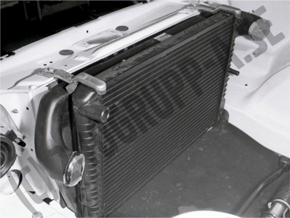 How do we know how big this radiator was? We don't have precise info and not all racing teams used the same radiator, but we do know the DIMENSIONS of the big GROUP A INTERCOOLER (Volvo PN 1352717). The original intercooler core dimensions can be used to compare radiator core size. Below I'll detail the Group A intercooler. A rabbit trail about the GROUP A INTERCOOLER or skip to next section: Other Intercoolers. This new intercooler BELOW, offered by do88 in Sweden, was created in the same dimensions as the original ETCC Group A intercooler. The originals were supplied by Langerer & Reich, the prominent company in Germany who supplied intercoolers for Porsche Turbo. This do88 intercooler has a core size of 600 x 415 x 52 mm (23.6 x 16.4 x 2 inches), so we can be pretty sure the oversized radiator shown above had a similar core size. Air Flow (measured at 0,15 bar (2,18 psi) pressure drop): do88 GrpA IC allows 440 CFM vs. standard IC at 286 CFM. 54% higher flow than standard. More dimensions and info below. https://www.do88performance.com/en/artiklar/volvo-240-grupp-a-replica-intercooler.html https://www.do88.co.uk/shop/volvo/performance-intercoolers/volvo-240-turbo-group-a-replica-do88-intercooler/ Also available in the U.S. at: https://www.fcpeuro.com/products/volvo-240-group-a-replica-intercooler 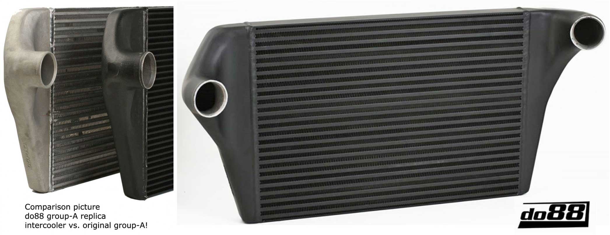 do88 Group A replica Intercooler DIMENSIONS. It should be noted that a number of web pages which list the core dimensions have an INCORRECT core height listed as 451 mm (17.75 in.). The CORRECT height measure by me is 415 mm (16.4 inches). I have informed do88 of the typo. If this was actually 17.75 inches tall, I don't think it would fit a 240 very well. The weight of this intercooler is 10.98 kgs (24.2 lbs). If you're fitting a wide radiator between the inlet and outlet, there's roughly about 29 inches of room between the inlet and outlet tubes at the inside curve (about 28.5 inches at the inside ends of the curves). If placing the radiator close to the core, the maximum radiator width will be roughly 27 inches. A wider radiator (up to maybe 28.5 inches) may also be possible if it's spaced a little away from the core. The extra outer width of this intercooler may not allow much room for a battery in the normal 240 location, so using an alternate smaller battery or moving the battery to the rear of the car might be necessary. 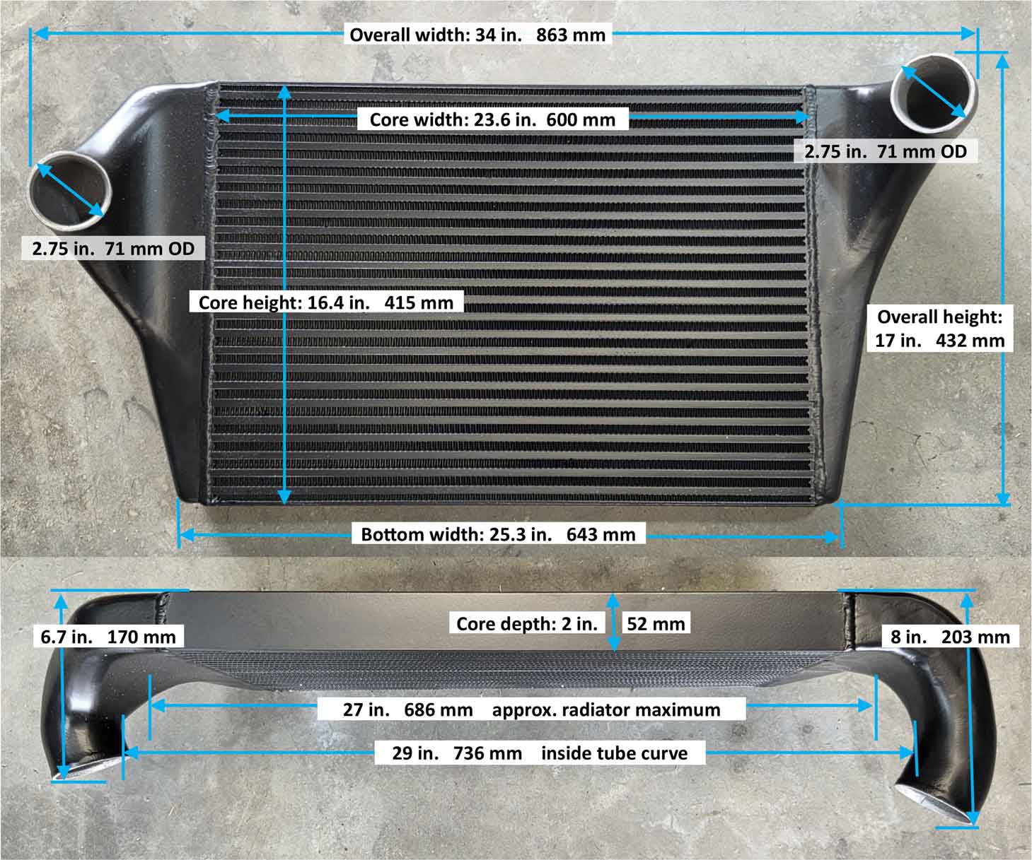 2 INCH CORE. Maybe you're looking at this and seeing the 2 inch (52 mm) thick core and thinking why so thin? So many other intercoolers are fatter, like 3 or 4 inches thick. Here's what I think about the core thickness. Very much like a radiator, this is a heat exchanger. It needs to be efficient. It needs to cool pressurize air fast. A thicker core might help for a radiator that's more limited in height or width, but I believe a THINNER core is ALWAYS more efficient as long as you have room for lots of surface area, like this one. So as long as the intercooler flows enough air and doesn't become a bottleneck, I think this is a great design. And since this intercooler flows 54% more CFM than stock, that should be a nice improvement. For the intercooler nerds out there, here's a discussion thread from 2016 with comparison tests involving do88 intercoolers. https://www.swedespeed.com/threads/do88-vs-elevate-ic.377873/ The do88 intercooler uses BAR and PLATE construction. Here's an outer close-up view of the core. 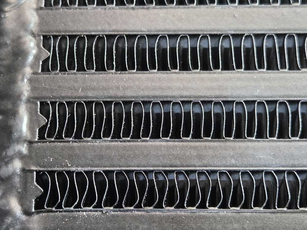 Here's a peek inside of the do88. 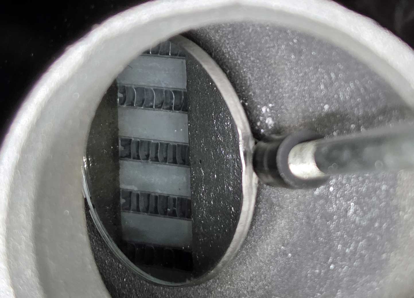 TECH ARTICLE: Garrett Intercooler Core Technology. https://www.garrettmotion.com/news/newsroom/article/garrett-intercooler-core-technology/ TECH ARTICLE: Mishimoto - The Ultimate Guide for Intercooler Selection. https://www.mishimoto.com/engineering/2015/04/drop-intake-temperatures-drop-track-times-drop-mouths-the-ultimate-guide-for-intercooler-selection Other Intercoolers. or skip to next section: Shopping for a Wider Radiator.
NPR Intercooler. This is the Izusu NPR intercooler, which gained popularity for Volvos many years ago because it was sized pretty close to the original Volvo intercooler. Plus it could be found used for a good deal. This intercooler is made to fit a radiator with a maximum width of about 23 inches, so it'll only fit a standard size 240 radiator. 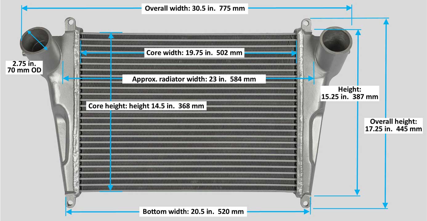 Here's a thread below where this intercooler is going in a 240. https://turbobricks.com/index.php?threads/nets-silver-245.366565/page-2 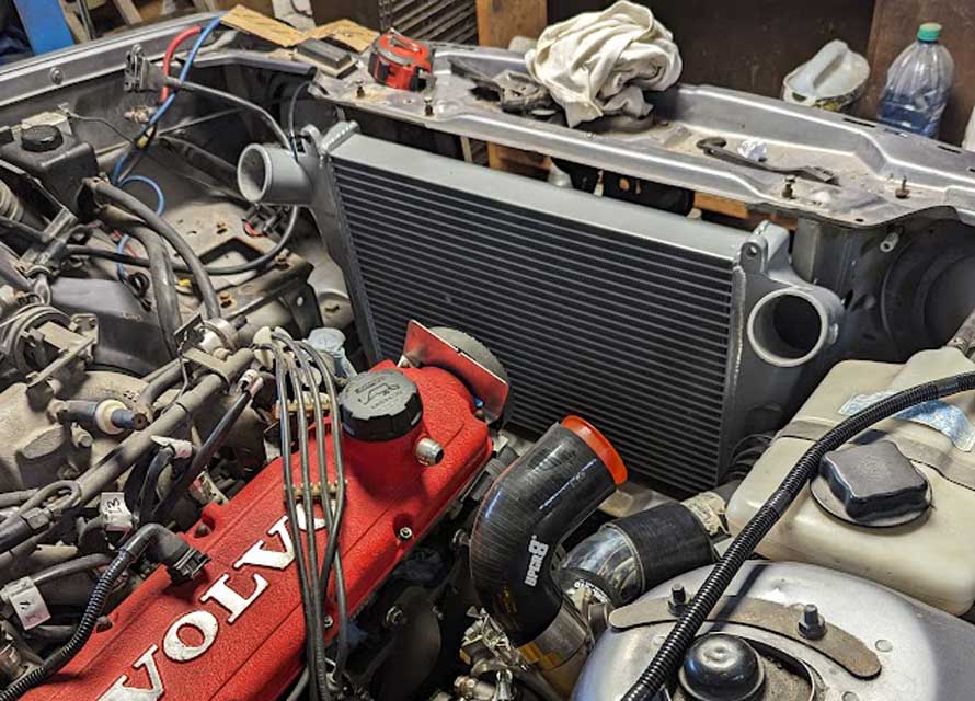 INTERNATIONAL Intercooler. This is an intercooler for International-Navistar that was used in a 240 in the below TB thread. It was bought used on eBay as a Modine 1E5620 Intercooler for International Truck. It has a 3 inch thick core and 3 inch inlet/outlet. Core width: 23.375 inches. Core height: 13 inches. It has 25 inches plus of room between the inlet/outlet for a radiator. https://turbobricks.com/index.php?threads/npr-intercooler-options-vs-do88.379575/ 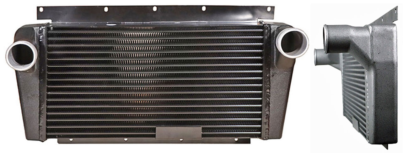 This is the upgraded aluminum version of the standard Volvo 240 intercooler in similar dimensions, except thicker and reportedly with 42% more CFM flow. This is do88 PN ICM-140. This intercooler is made to fit a radiator with a maximum width of about 23 inches, so it'll only fit a standard size 240 or 740 radiator. Comparison to a Standard Volvo Intercooler. Core volume: do88 is 11906cm3 vs. original 5377cm3. do88 is 221% larger. Air flow measured at 0,15 bar (2,18 psi) pressure drop: This do88 has 405 CFM vs. standard 286 CFM. 42% higher flow. DIMENSIONS: Width at top: 725 mm (28.5 in.); Width at bottom: 508 mm (20 in.); Core height: 440 mm (17.3 in.); Depth with connectors: 95 mm (3.74 in.); Core thickness: 63 mm (2.5 in.). https://www.do88performance.com/en/artiklar/volvo-200_700_900-turbo-81-98-intercooler.html https://www.ipdusa.com/products/21027/1169/1988-Volvo-740-Turbo-Performance-Aluminum-Intercooler-200-700-900-1991-Do88-ICM140 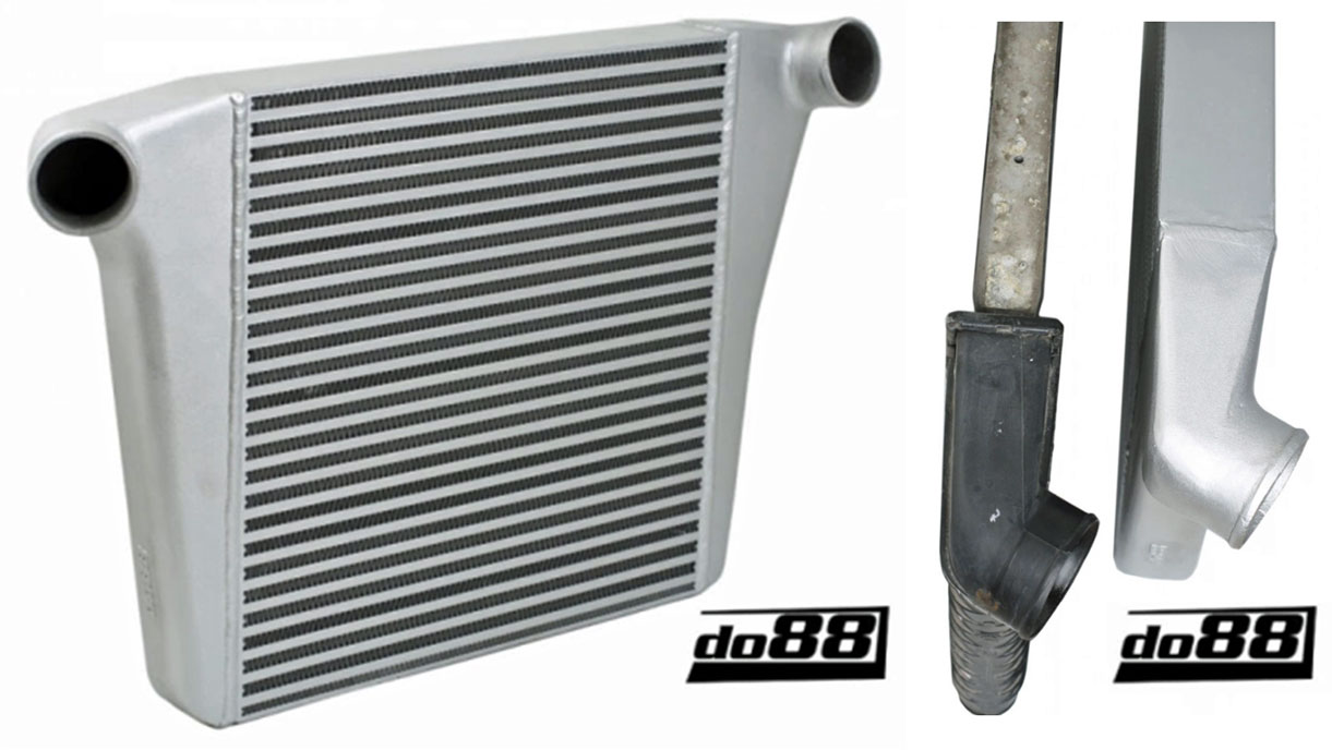 This is do88 PN ICM-150. This intercooler from do88 is sized as an upgraded replacement for a 1992-98 Volvo 940 Turbo. It's too tall for a 240 as is, but if those two top pieces were removed, I think the overall height will be only 15.5 or 16 inches. Overall size: 899 x 510 x 109 mm (35.4 x 20.1 x 4.3 in). Core size: 610 x 395 x 50 mm (24 x 15.5 x 2 inches). Inlet/outlet size: 60 mm (2.36 in.). Weight: 11.5 kgs (25.4 lbs). This size intercooler is made to fit a 28 inch wide 940 radiator. It offers 28% more CFM flow than a stock 940 intercooler. https://www.do88performance.com/en/artiklar/volvo-700_900-turbo-92-98-intercooler.html 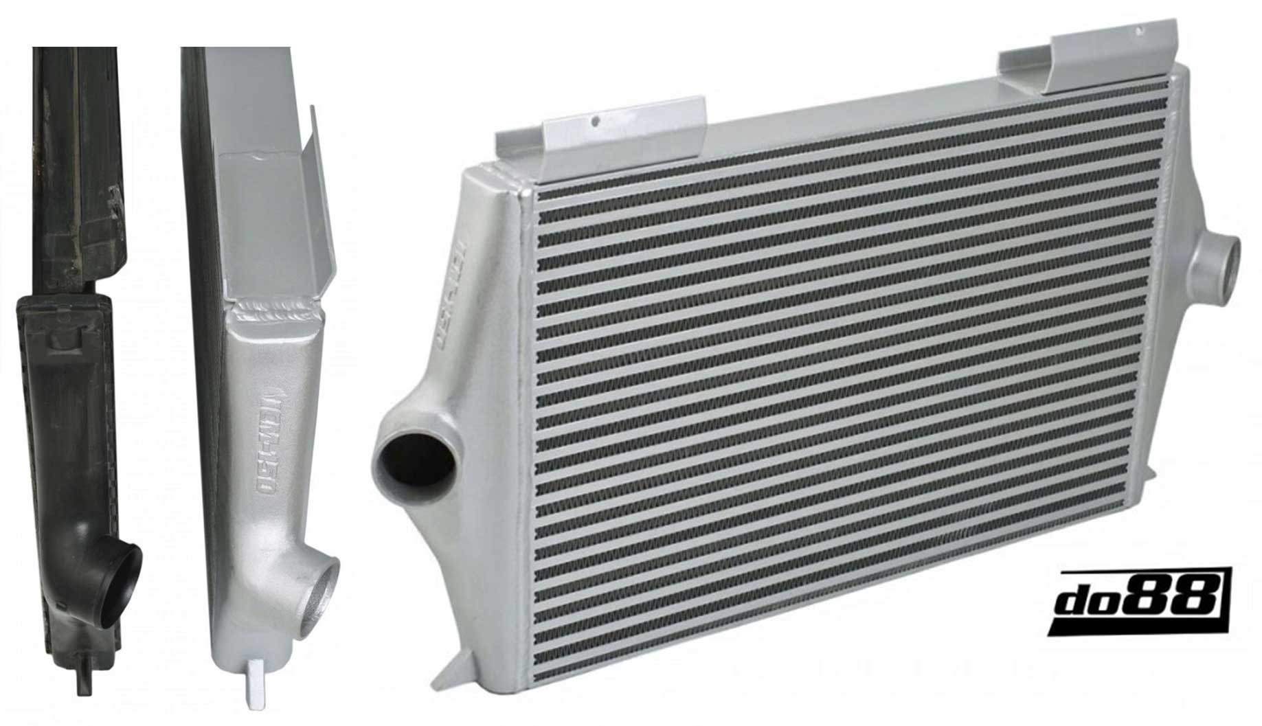 Here a video below featuring this intercooler being installed in a 740. https://www.youtube.com/watch?v=Bc90dO_ajiM UNIVERSAL INTERCOOLER. Sometimes a universal intercooler can be a better fit for a wider radiator or a custom installation, allowing more flexibility in positioning intercooler pipes around the radiator. This 600 x 300 mm core size is very common among universal units. This one below from do88 is PN IC-120. If you're considering a universal, you should try to find out if the manufacturer offers CFM airflow measurements. This bar and plate core design flows about 330 CFM at 0,15 bar (2,18 psi) pressure drop, which is about 15% higher than a stock Volvo 240 intercooler. Also when you're shopping you might ask if any temperature reduction data is available. Considering the core quality do88 uses, I would expect great results from any intercooler they offer.. Overall size is 780 x 300 x 80 mm (30.7 x 11.8 x 3.15 inches). Core size is 600 x 300 x 76 mm (23.6 x 11.8 x 3 inches). Inlets and outlets are 63 mm (2.5 inches). https://www.do88performance.com/en/artiklar/intercooler-600x300x76-25.html 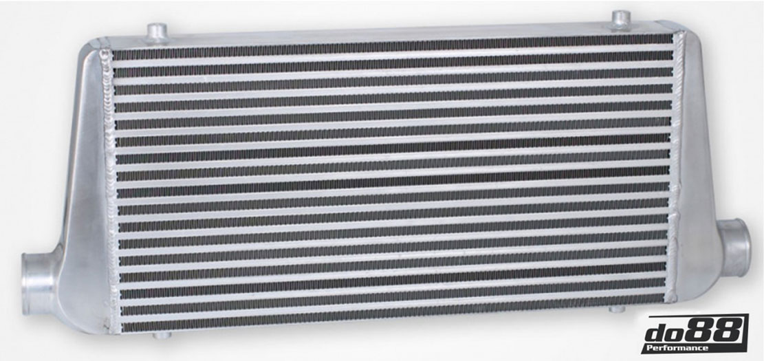 A universal intercooler like this from do88 will be more expensive than one you can find on Amazon or eBay, but I think you should also consider the quality and performance factor. Plus I don't know if any Amazon or eBay intercoolers offer trustworthy CFM specs or cooling specs. And I've heard about poor temperature reductions for some no-name Chinese units with inferior internal fin designs. AND I think it's very important to support businesses which make COOL PARTS for our Volvos, so we can continue having nice things. 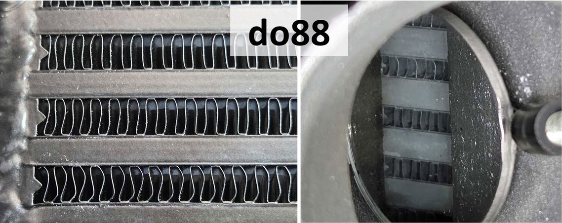 Probably not all Chinese intercoolers have a low internal fin count like this one on the right, but I suspect this 600 x 300 mm unit from eBay will not perform nearly as well as a proper do88 intercooler. 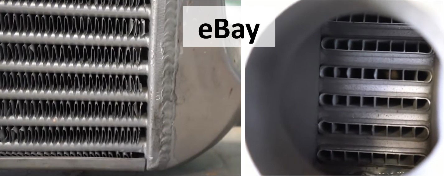 This video discusses this subject: 'Not all Intercoolers are Made the Same.' https://www.youtube.com/watch?v=oUJNKaoSMIA And when it comes to INTERCOOLERS, more than one core design is possible. 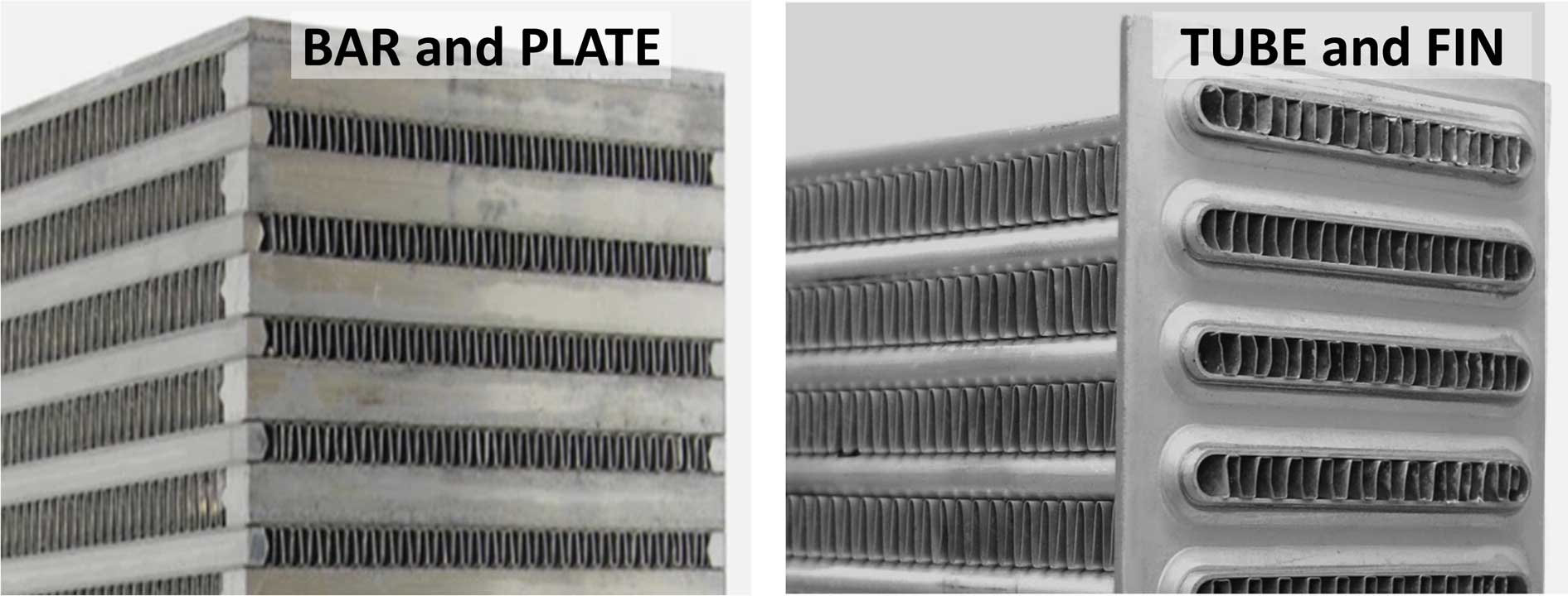 It's sometimes hard to tell from the outside which design an intercooler has. Most aftermarket intercoolers use a BAR and PLATE design. A stock 240 Turbo intercooler uses TUBE and FIN. Both designs have pros and cons. Here's a video showing more detail about these different styles. 'PlazmaTech EP:1 - Bar & Plate vs Tube & Fin Intercoolers.' https://www.youtube.com/watch?v=7P7KanLrZko In 2012 I started shopping for a WIDER radiator for my 240. or skip to next section: Improved radiator Efficiency Design.
I wanted to try a wider radiator, hopefully without having to get something custom made (and super expensive). After a long search, I bought this one below from Griffin Radiator in South Carolina. PN 1-55221-X, which was in their UNIVERSAL radiator section. The cost was under $300, not including having some end tank fittings added, which were done locally. If you're wondering why I didn't return to Ron Davis, that's in the Ron Davis section above. And all my cooling issues suddenly vanished under all conditions! 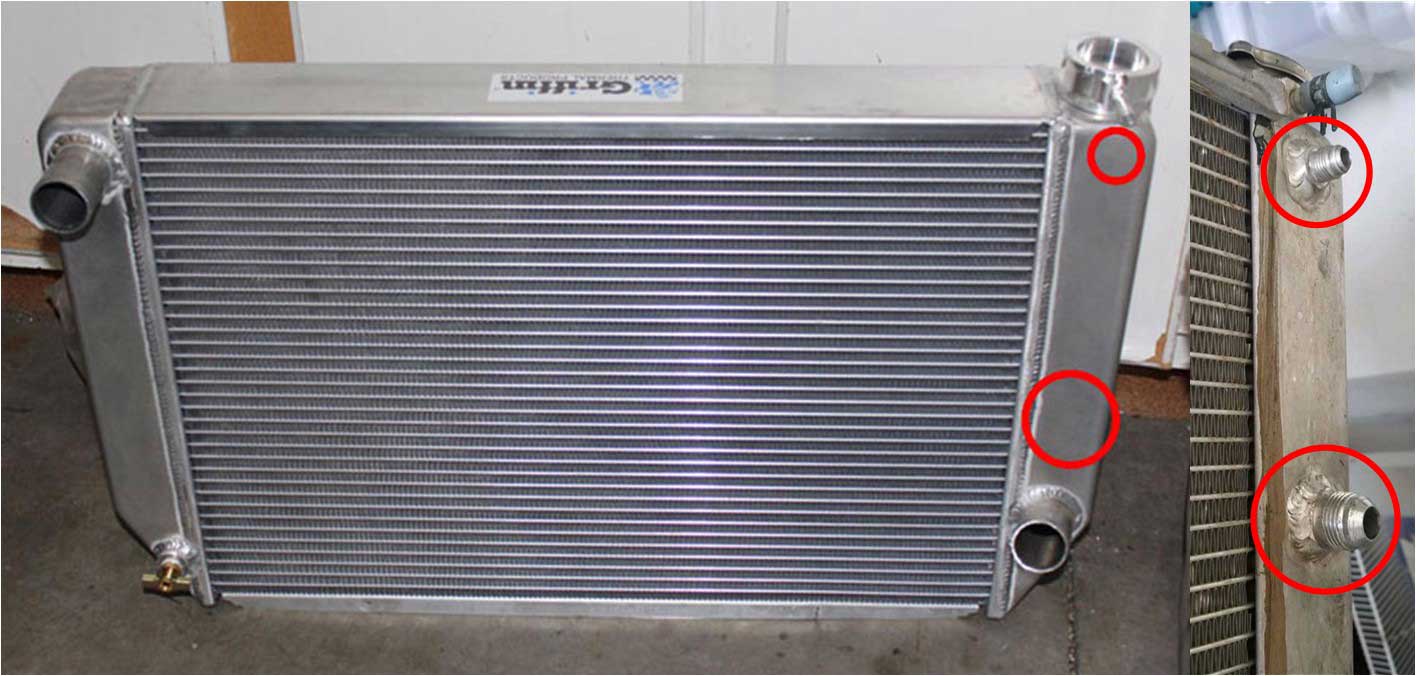
With this 2012 Griffin being a UNIVERSAL radiator, it was not a perfect fit. The overall size was 26 x 15.5 inches x 3 inches thick (660 x 394 x 76 mm). Core size was 21 x 15.50 x 2.68 inches (533 x 394 x 68 mm). This radiator was about 3.5 inches wider than a stock radiator). It had two rows of 1.25 inch (32 mm) cooling tubes, which are bigger than the Ron Davis tubes. And Griffin also offers 1.5 inch tubes if more cooling is needed. 26 inches wide was a pretty good width. It was a little shorter in height than I would have preferred. 17 or 17.5 inches tall might have filled up the space better in a 240, but I was happy with it for the 10 years I used it. 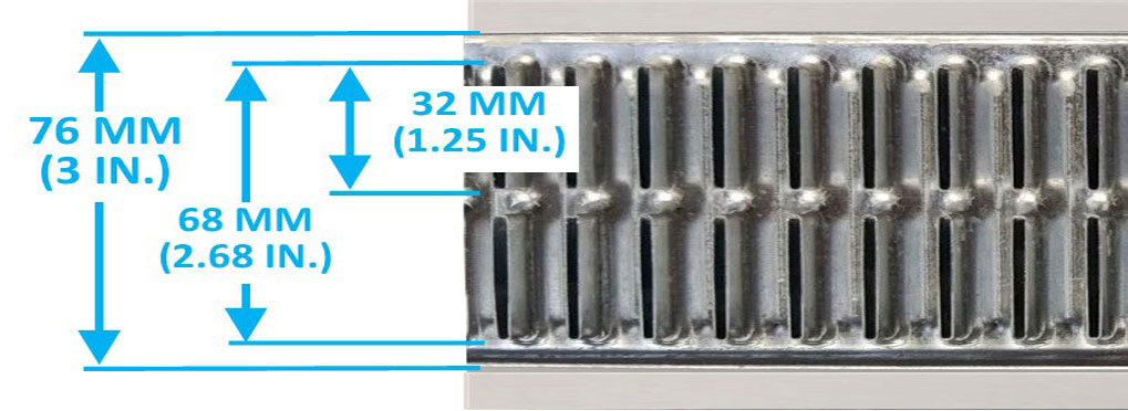 Here below you can see how the wider 2012 Griffin UNIVERSAL looked in the car. This fan and shroud below is a Lincoln Mark VIII 18 inch brushed fan. It did a great job of pulling air, but it used a lot of amperage. A big fan is OK, but it should be controlled so it's not running hard when the engine only needs a little bit of air, which is most of the time with a nice big radiator. I eventually solved the fan control with a PWM variable speed controller CLICK HERE. 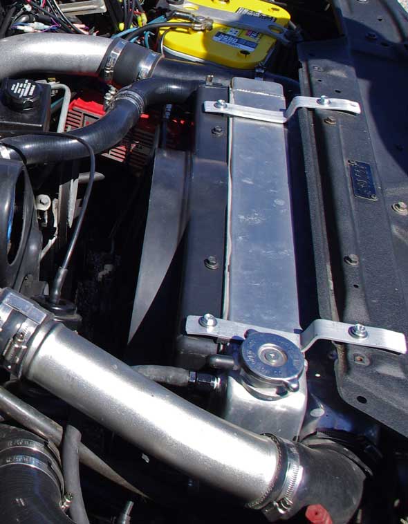 In 2022 I had Griffin build a NEW CUSTOM RADIATOR to my own specifications. My old 2012 Griffin accidentally got damaged and the core was leaking, so I needed a new one anyway. The new one is a little wider and taller. New size: 26.5 x 17 x 3 inches (673 x 432 x 76 mm). Core size: 22 x 17 x 2.68 inches (559 x 432 x 68 mm). The core has two 1.25 inch (32 mm) wide cooling tubes, same tube size as the last Griffin. They offer cooling tubes up to 1.5 inches wide if more extreme cooling is needed. 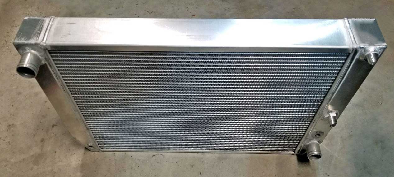 This radiator is working exceptionally well. The new fan BELOW installed in 2022 is an 18 inch brushless fan with shroud, which is controlled by a standalone programmable PWM controller, which reads directly from my coolant temperature sender in the head. It only runs as fast as needed for the temperature, so it's always perfectly stable, even under very heavy use. More on all this at https://www.240turbo.com/BrushlessFans.html#JKfan 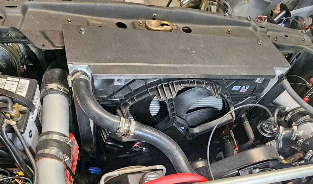
So if you're going to ask my opinion of what to prioritize if you're modifying a 240 Turbo for more power, I will tell you before you start on engine development, work on fitting a BIG RADIATOR. Don't wait to do this kind of improvement after all your other work. And don't listen to others who tell you it's OK to live with a marginal cooling system under hard use. And also try to improve the air ducting in front of the radiator. More on that coming below. Some of you might wonder how I mounted an 18 inch fan and shroud on a radiator that's only 16.5 inches tall. I considered lots of different options. One was dual fans. I concluded that the core size of this radiator would only allow for dual 10 inch fans. That wouldn't do at all. One 18 inch fan has more area that two 12 inch fans. I had years of experience with large electric brushed fans going back to 2010. 1. 1989-93 Ford T-Bird SC (Supercharged) 17 inch fan; and 2. 1997 Lincoln Mark VIII 18 inch fan. And this latest one, a 2012-2018 Jeep JK Wrangler 18 inch brushless fan. I did the same thing for all of them. I allowed the bottom 3 to 3.5 inches to hang down past the bottom of the radiator. I used sheet aluminum to seal off that bottom overhang. 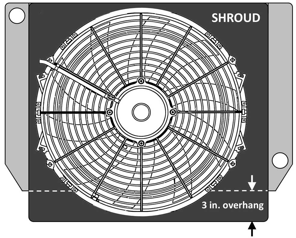 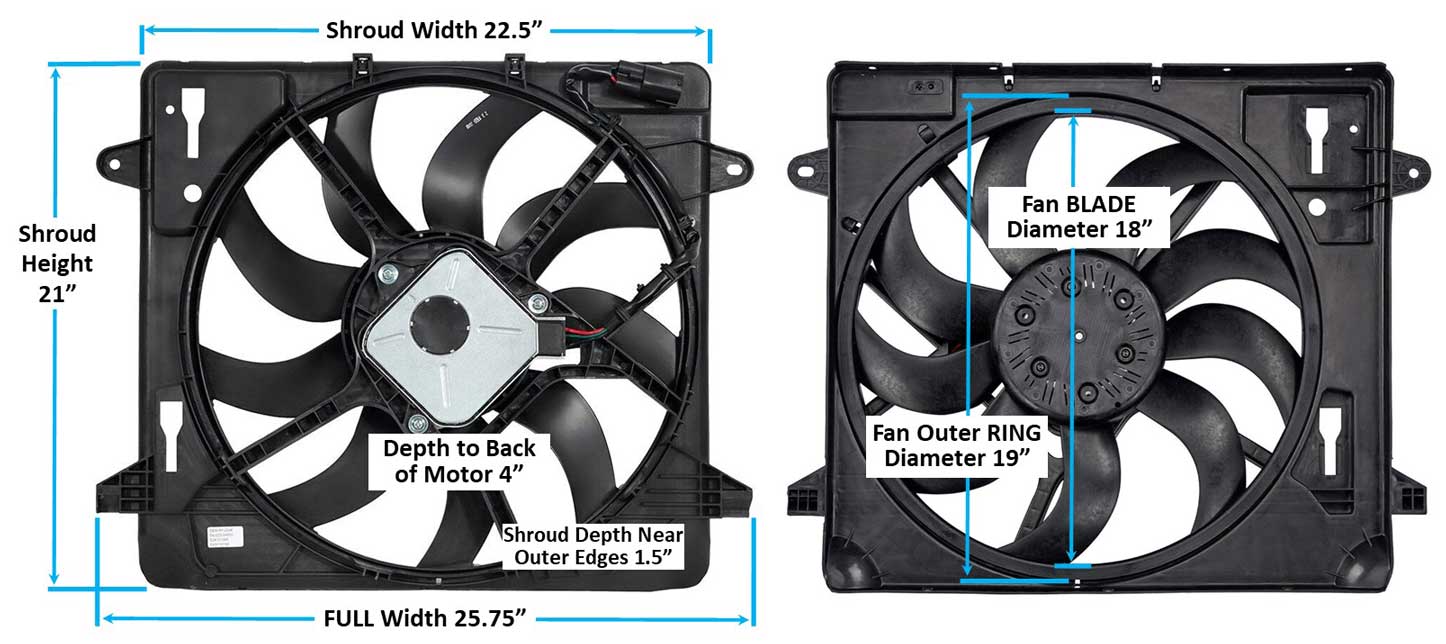 More on all this at https://www.240turbo.com/BrushlessFans.html#JKfan 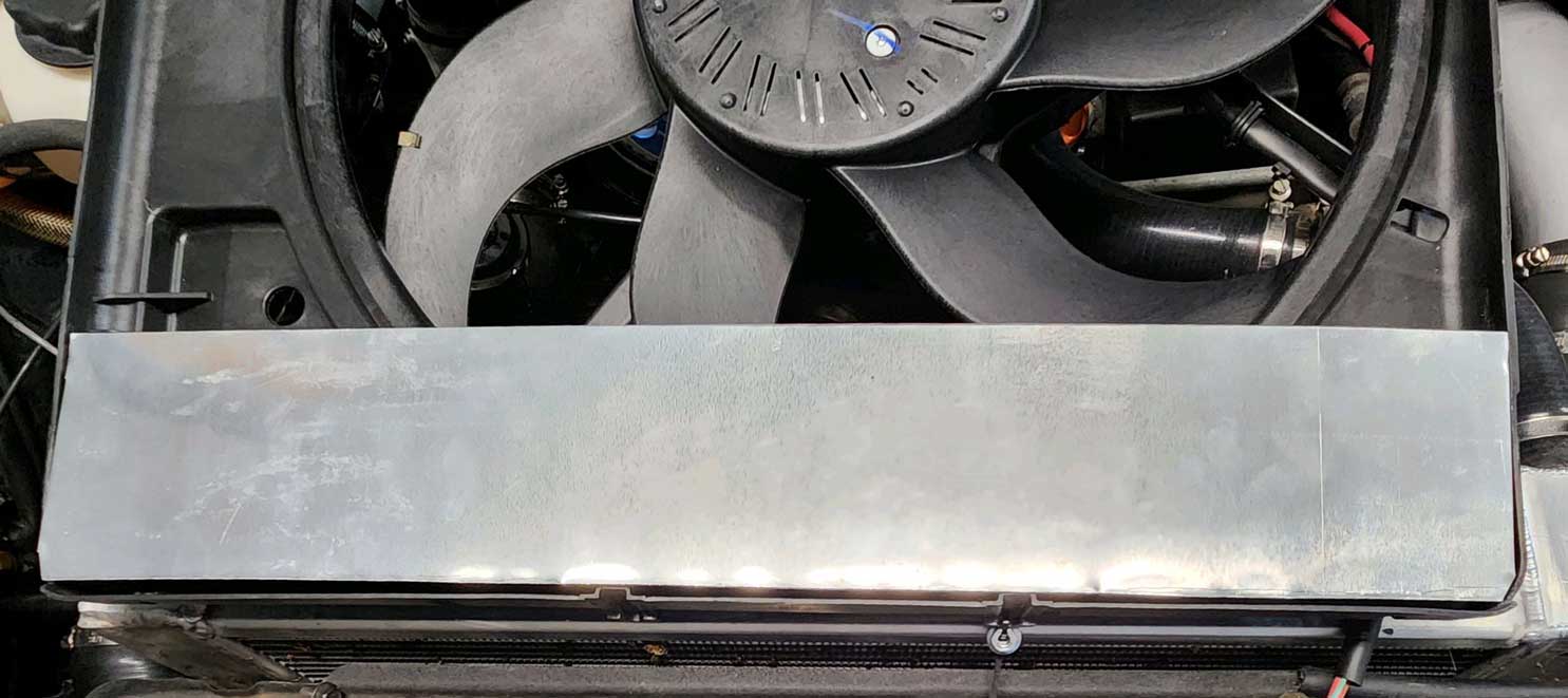 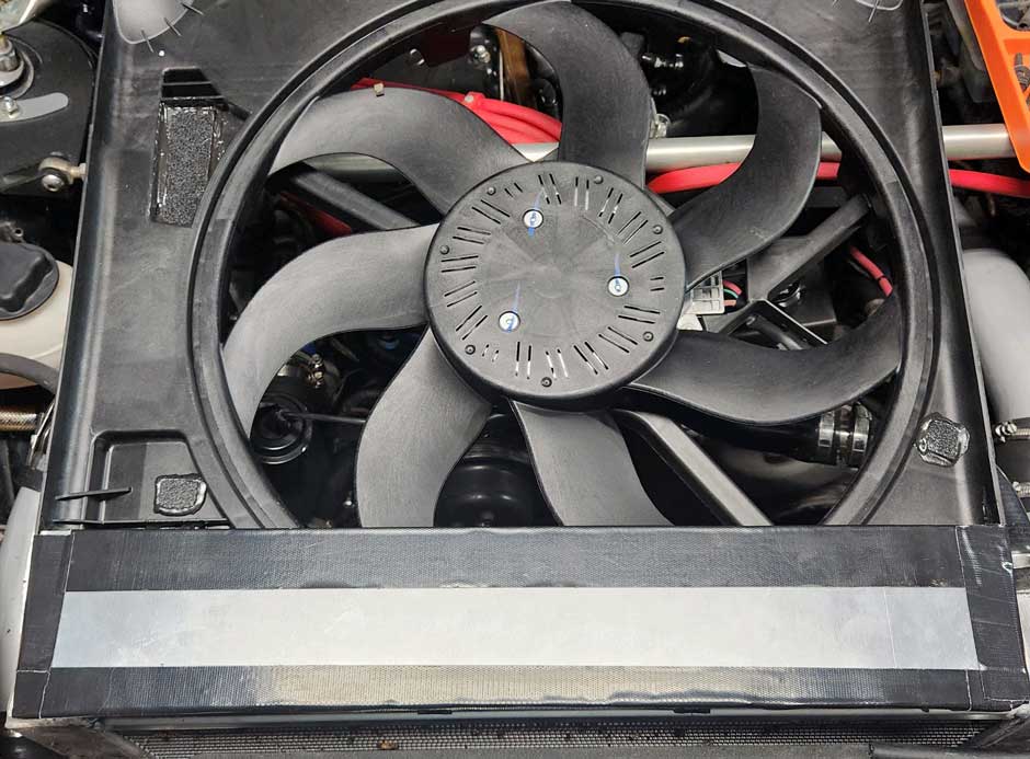 Improved Radiator Efficiency Design? or skip to next section: Radiator Air Ducting. Choosing a radiator with 1 row, 2 rows, 3 rows, 4 rows, etc., or one that's wider or with a larger surface area can be a hard decision, especially because you're spending serious money. I think the best answers can be found if you carefully study different designs and trying to filter out the sales pitches. It's rare that cheap deals work out well in the end. So in most cases, accept that you won't get off cheap. My journey has taught me that shooting for the MINIMUM cooling capacity that you can survive with or making many small improvements to an UNDERSIZED system will rarely result in happiness. If you set your goals for MORE cooling capacity than you think you need, I think that will work out much better. Cooling Tubes Most radiators use flat oval shaped cooling tubes, sometimes call rolled tubes. 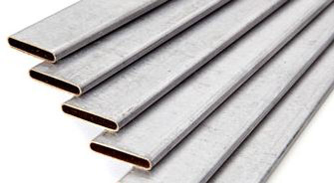 These are made in various sizes and a radiator company will usually offer what they like to use for economy, efficiency or reliability. Cooling tubes can be made of different wall thicknesses. Thinner walls will always be preferred for the best heat transfer. But thinner walls can result in less strength, so a reputable builder will choose a compromise to offer a radiator that will last. The type or grade of metal can also be important when considering how strong a thin wall tube can be. There are also alternate oval tube designs that may be highlighted by some companies who claim their designs are stronger, more efficient, etc. Shapes like this are sometimes called B-tubes.  Which is better? Is THREE rows better than ONE? I used to think the answer was usually YES. But no longer. 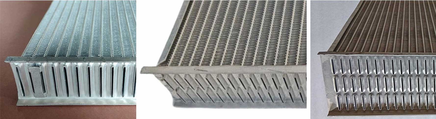 Maybe more rows is better in some cases, such as if your overall size can't be made any wider or taller. But if you CAN go with more surface area, I would put that ahead of more rows. I think a complimentary theory for more rows is that it can offer more surface area in contact with coolant. But there are drawbacks and limitations that come with fatter radiators. 1. The fatter core makes it harder for air to get through cleanly. 2. The air that gets through cools the first row well, but that efficiency decreases as the air gets hotter and the next rows don't get cooled as well. In the end, I think the first priority will often be to fit a radiator with the most surface area you can reasonably fit. If that radiator turns out to be big enough to be efficient with only one row, I think that would be great. Are there potentially more advanced CORE DESIGNS besides traditional rolled tube? There are. Many of them are in use or have been in use for a long time. There are some high-tech designs used in more expensive radiators or in racing. These tubes below are often called Stuffed Tubes or Strutted Tubes. Similar to a traditional wide rolled tube, but with added metal structure (or struts) inside to potentially increase heat transfer. Many designs like this seem to be recommended only for air cooling, such as for intercoolers. 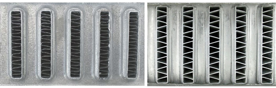 EXTRUDED TUBES Some manufacturers will use the term extruded tube, micro-tube or micro-channel. It appears tubes like this can be used for radiators, oil coolers or intercoolers. The examples below are all extruded aluminum tubes. Extruded tubes offer a structurally stronger design (thicker material) with more defense against external damage. Designs like this can also handle much higher internal pressures, which makes them suitable for oil coolers or for more rugged environments. This type of design is common in commercial or industrial equipment. There are some design claims that a one row radiator with an extruded tube like some of these could offer the best of both worlds. 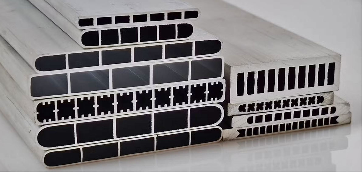 Here's an example showing how radiators using extruded tubes like above are offered for high performance cars. A company called ARC in Japan makes high-end radiators with "super-micro-tubes" for a limited number of Japanese cars. These appear to use ONE wide extruded tube, which has dividing walls to created a number of channels. They claim to have a substantially increased cooling capacity. https://www.nengun.com/arc/super-micro-radiator 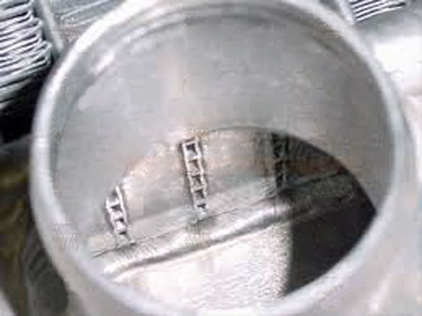 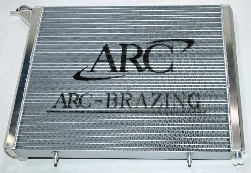 As it turns out, there are places in the U.S. who offer EXTRUDED TUBE core radiators. I can't say if this is a better option for a street car or a race car (THERE'S an opinion below that says it's NOT BETTER). The argument surrounds the efficiency of thicker wall extruded tubes compared to the thinner traditional tubes. If there are any useful tests comparing this to traditional thin-wall rolled tubes, I'd like to know. 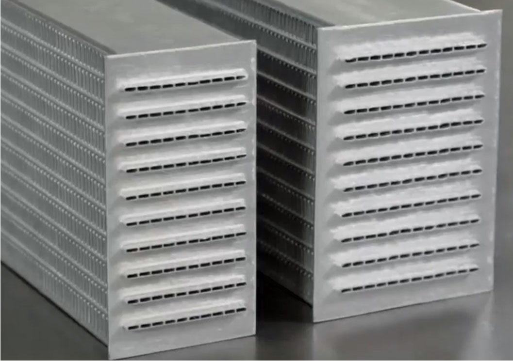 C&R Radiator: https://www.crradiator.com/automotive-radiator Here's a video: https://www.youtube.com/watch?v=0-EDcEMBs28 Here's an OPINION which says EXTRUDED TUBE radiators are NOT better for cooling? There's this opinion below from DeWitt's Radiators. They point out that extruded tube walls are considerable thicker than traditional thin-wall rolled tubes: 20 to 40 thousandths thick (0.020 to 0.040 inch) compared to 10 to 15 thousandths (0.010 to 0.015 inch) for rolled tubes. DeWitt's believes the thinner tube walls of traditional rolled tubes will reduce the thermal barrier BETTER, providing more rapid and more efficient heat transfer than a thicker extruded tube. https://www.dewitts.com/blogs/news/are-extruded-cooling-tubes-better If anyone comes across any useful tests comparing efficiency of tube types, please let me know. Perhaps if extruded tube technology allows for THINNER WALLS in the future, this opinion above might change. Formula One and Indy cars are using styles of micro-tube radiators which have many thousands of very small round tubes (as small as 2 mm). These are designed for a lot of free air flow around the tubes for aerodynamic gains. A radiator like this is also made to be extremely light and it's very easy to damage. 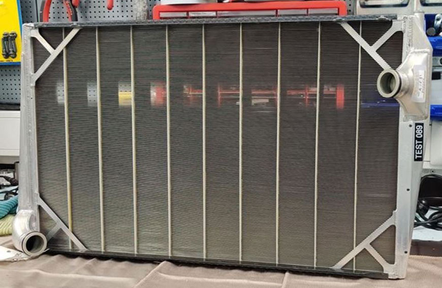 Here's a video with more info about F1 and Indycar radiators. https://www.youtube.com/watch?v=9rs5QMk40IQ Radiators using small round tubes is not new. Some early European car manufacturers were using designs like this 1921 Renault radiator a long time ago.  What is Good Radiator Air Ducting? or skip to next section: Coolant Maps. Your radiator needs as much air directed through it as you can get. Lots of older Volvos don't have a very good air ducting in front of the radiator and it may be worse after some modifications. When traveling at highway speeds and that 70 mph air is going through your grill, how much of it is FORCED to go through your radiator and how much is able to escape and go around it? If you remove your grill and can see openings in there where incoming air can go to the left or right or under, those places can be closed off with a little effort.  This radiator ducting photo BELOW came from Björn Ohlson's 240 Grupp-A page https://240grupp-a.se/kylning/. 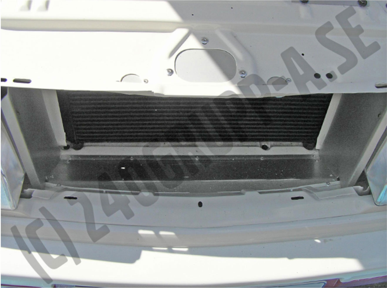 This kind of thing doesn't have to look fancy like on the 240 race car above or this 740 race car below. It doesn't have to be aluminum either. 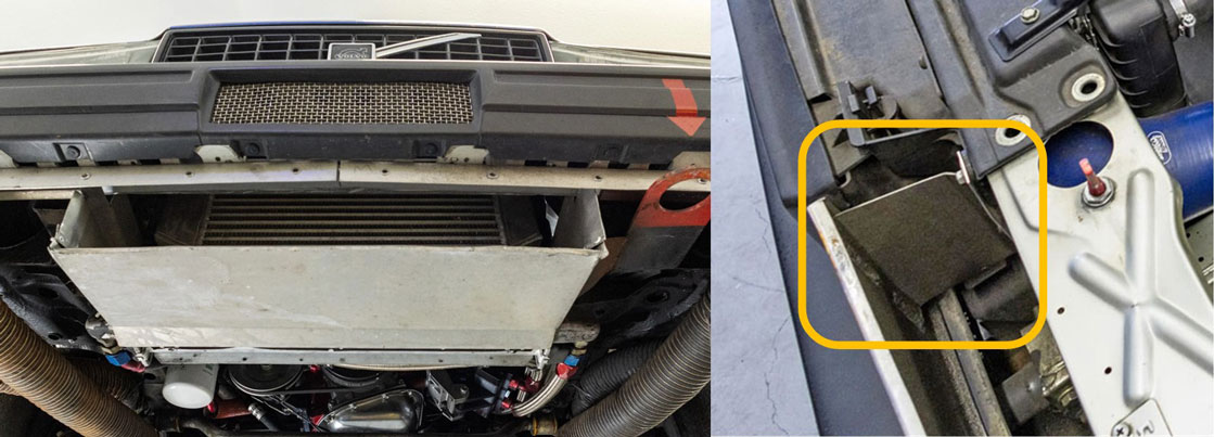 When I've done this type of work before, I've started by cutting some sheets of cardboard first to find some shapes that will fit in there. You might need to make multiple overlapping sheets for some places, depending on how much room there is and what obstacles are interfering. Once I have some cardboard shapes that will work, I then transfer those onto 1/16 inch ABS plastic sheets. You can buy ABS plastic sheets at Home Depot or other suppliers in sizes like 24 x 48 inches x 1/16 inch thick for about $25. ABS is strong and can be cut with tin snips or strong scissors if it's only 1/16 inch thick. ABS can also be bent or formed with some help from a heat gun or warming in a oven to about 300° F (Hot, use gloves). Your final pieces can be secured with zip-ties, so they can be removed easily when working on your car. An important word about Fan Shrouds. Sometimes modifications get done and important things get left out by mistake or because of ignorance. Primary cooling fan shrouds can get damaged and sometimes don't get replaced. And so often I see images like this below with a simple puller fan and no shroud. Don't do this for a street car that needs to stay cool in traffic, etc. If this fan below is 16 inches across, you can expect to only cool a 16 inch circle on this radiator. Every cooling fan becomes MUCH LESS EFFICIENT when no shroud is present. Plan ahead to always find a way to include a proper shroud for your primary cooling fan project. 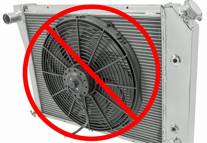 Cooling System Flow Maps B21, B23, B230. or skip to next section: Adding a Coolant Bypass Valve. This basic cooling system diagram comes from TP31311 Design, Function B204, B234 Engines 1988+, page 236.  The below UNMODIFIED cooling system maps will help you follow along in this page with a better understanding of coolant flow. I made these coolant maps to help you understand this better. In the below unmodified map, LOCATION #1 shows the first entry of coolant from the lower radiator hose into the water pump inlet. LOCATION #5 shows coolant exiting the rear of the cylinder head and going to the firewall. In a 240 or 740 the coolant flowing through the firewall will be interrupted by the heater valve, which is controlled by a cable in a 240 or vacuum in a 740. When the factory heater valve is set to COLD, the valve will always be closed. This closed position means no coolant will circulate, so then no coolant can flow out of the back of the cylinder head unless the valve is open. There might be circumstances where you might WANT to allow coolant to flow out of that back head port, potentially for head cooling improvement. Unmodified Factory Map 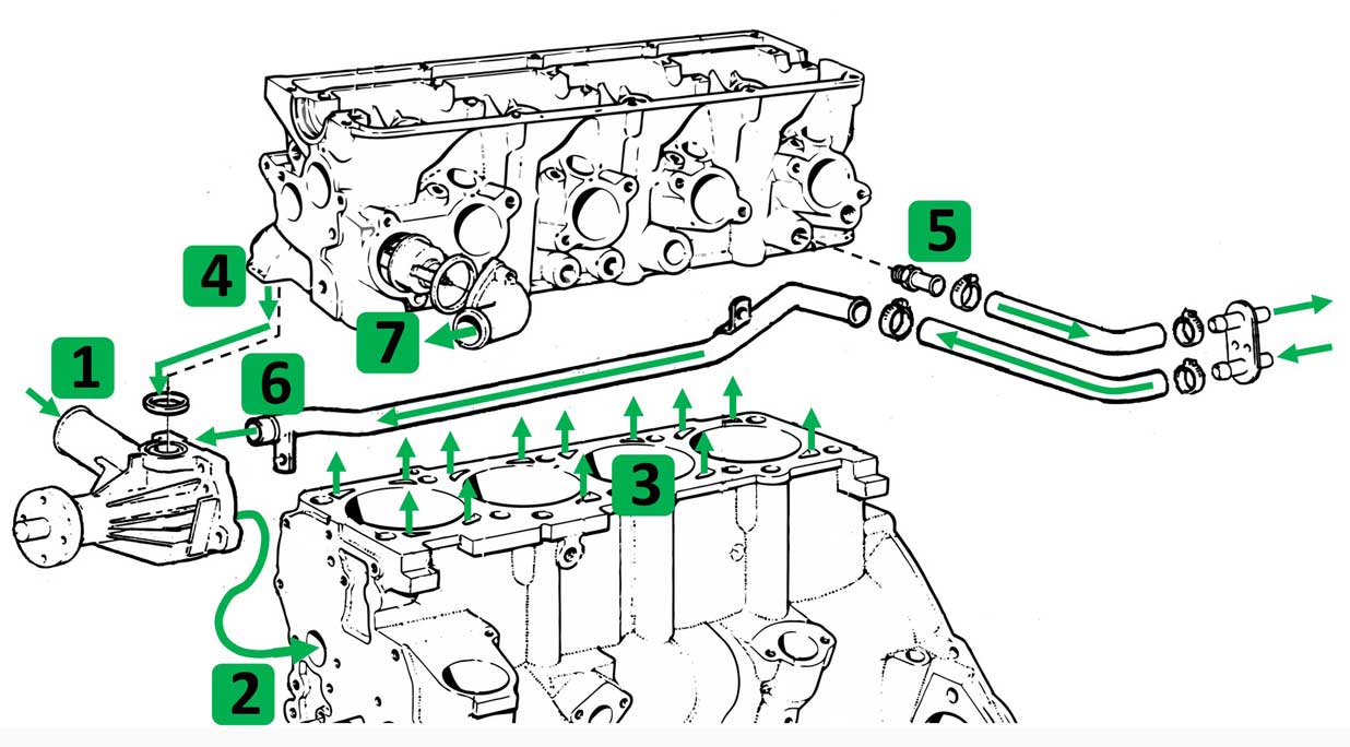 If you have questions about the flow direction at Location #4 into the water pump, CLICK HERE. 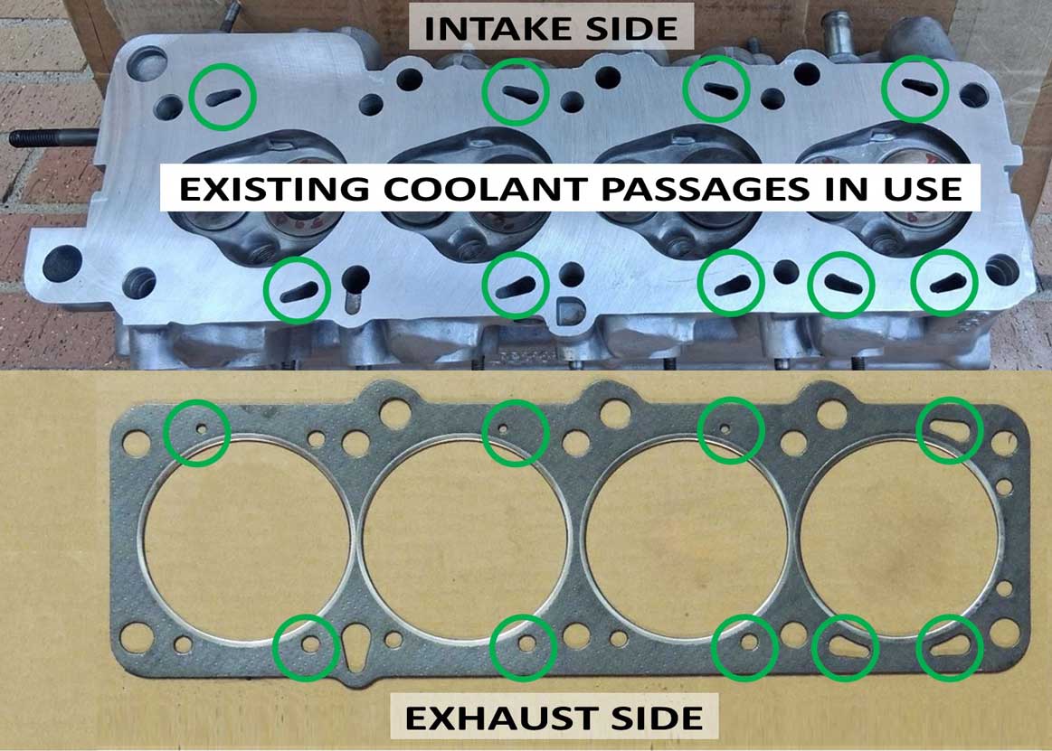 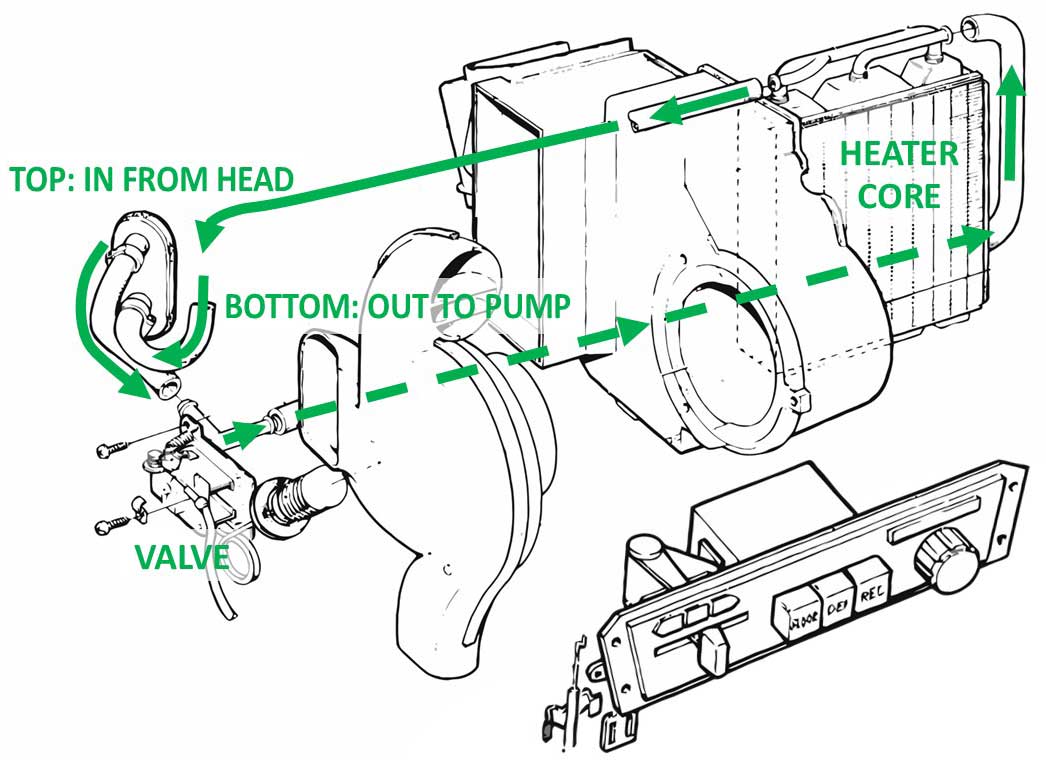 Some more relevant Cooling Info Links CLICK HERE. Modifications: Adding a COOLANT BYPASS VALVE. or skip to next section: Stealthfti CONTEXT: This discusses adding a bypass valve to bypass a normally closed heater valve in the dash. This will discuss adding a 4-port coolant bypass valve to the existing heater hose circuit to allow full-time circulation of coolant from the back of the head. There's more than one way to do this and this has been done by some Volvo owners. A bypass valve can be on either side of the firewall, depending where you find it fits best. I'll offer some ideas and share what has been discussed or used by others before. I own a 240, so please forgive me if most of my info tilts toward that car. Lots of info here is also relevant for 700-900 models. If you're curious about some example bypass valves, you can review that BELOW. 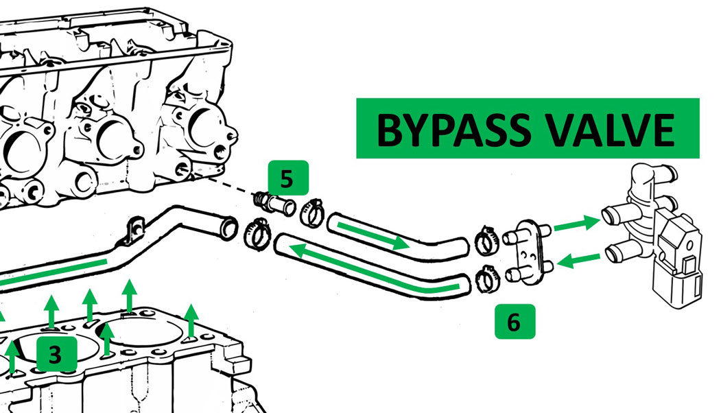 Typical 4-port bypass valve flow diagram. 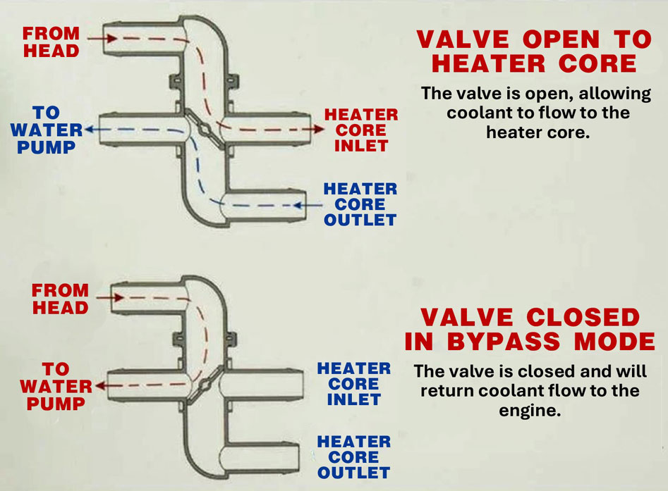 Why would this modification interest you? or skip to next section: Selecting a Bypass Valve. There are plenty of people who think Volvo engineers were at the pinnacle of knowledge and there's no real need for improvement in an old Volvo. Those people drive completely stock non-turbo cars without AC and have no need for this page. I really believe the Volvo 240 cooling system was designed to a MINIMUM for a NON-TURBO engine without air conditioning. Should Volvo have considered increasing the capacity when they got to the TURBO cars or when air conditioning became more common? YES, but they didn't. The only increase in capacity for a turbo car was adding an oil cooler for the oil-cooled turbo (more in my Oil Cooler Page). Plus later (for some 1984 models) they added an electric condenser fan for AC cars. When turbos would later change or get upgraded to water cooled versions, would that have been a good time to increase cooling capacity? What about when INTERCOOLERS were in the planning stages? Maybe Volvo engineers wanted to, but if they did they were told "NO." After all, the cooling system was probably just fine for northern Europe. The general reasoning for doing this bypass mod is that by allowing the hot coolant to circulate out of the back of head, we can potentially improve head cooling, particularly in the rear cylinder head region where it can be known for running hotter. Turbobricks discussions have reported real world improvements using a bypass valve to accomplish this. You can read in this TB thread below about user stealthfti's success with a bypass. https://turbobricks.com/index.php?threads/8v-b230-cooling-system-modification.121189/ Steathfti went further with a more advanced modification. He also bypassed the coolant return pipe and instead sent hot coolant from the head to a "Y" or "T" fitting in the top radiator hose. An invaluable excerpt from stealthfti's comments: The SOHC cooling system works well until the RPMs exceed 3200....steady state. Above 3200, the internal flow paths of the coolant inside the head . . . BCP or SCP . . . becomes too turbulent [as in too many cross-currents] to actually prevent dead zones and steam pockets. I tried LARGE radiators. I tried different thermostats. Even different brands of water pumps. The ONE thing that KEPT the coolant temp stable at 4200 RPM, regardless of ambient temps from 0°F to 100°F, was using the heater hose head outlet to bypass coolant from the back of the head to the upper radiator hose. https://turbobricks.com/index.php?threads/8v-b230-cooling-system-modification.121189/ [NOTE: Thomas Fritz, AKA: stealthfti, passed away in 2018] I've created a general illustration below showing how coolant might be returned to the top radiator hose. 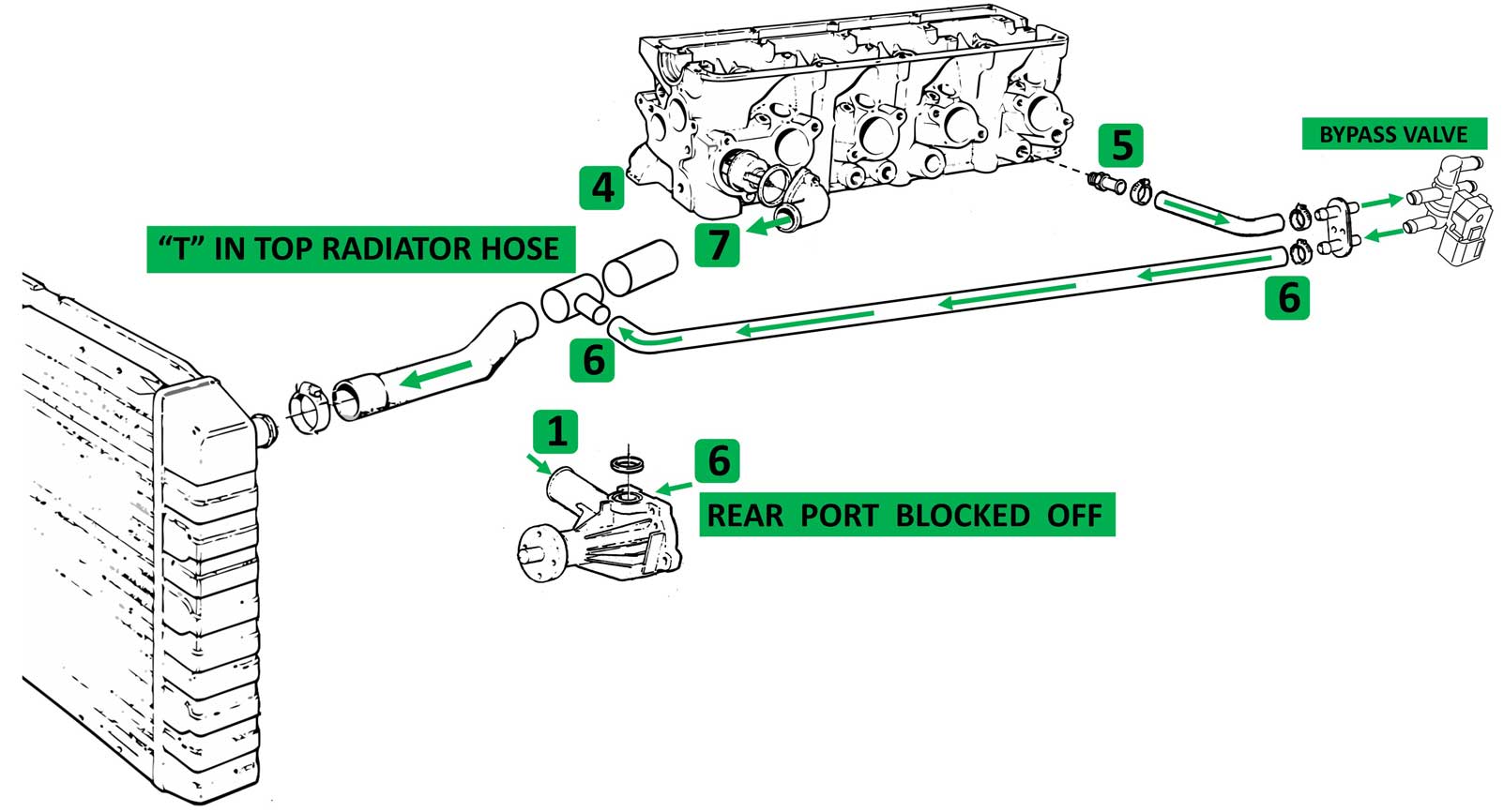 There's a question about this that may not be answered until someone tests this more: We can expect the coolant to have no problem exiting the rear cylinder head port, because there will be some positive pressure pushing it. However, when the coolant returns from the firewall to the upper radiator hose TEE, will the coolant have any trouble flowing into it? Or will there be nearly EQUAL pressure from the coolant coming from the thermostat. Could that stall or interfere with the flow? The comments from Stealthfti suggest that flow will be fine. But how do we know? I suppose if this became a concern, an Electric Booster Pump (EBP) could be used to help push it along, similar to the info outlined HERE. Also the idea that this extra flow out of the head might reduce temperatures TOO MUCH was discussed. So it would be a good idea to check temperatures at various places. A restrictor valve could be added if needed. Selecting a BYPASS Valve. or skip to next section: Water Pump REAR Port. This first 4-port bypass valve below has a VACUUM DIAPHRAGM to cycle it OPEN or CLOSED. If vacuum is present the valve will be closed. This valve is ONLY either OPEN or CLOSED. It does not appear to have a partial open function. This type of valve is discussed further in this Turbobricks discussion below for use in a 700 model. A vacuum controlled valve may or may not be appropriate for a 240. You'll have to make that decision if you feel that a such a valve is right for your car. https://turbobricks.com/index.php?threads/7-9-updated-heater-control-valve.246617/. 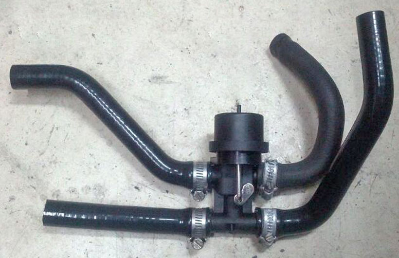 AFTERMARKET PART QUALITY NOTE: Having a quality, leak free valve is super important. A leaky one will not be worth the trouble if it saved you a few dollars. The above TB discussion discovered some cheap valves that people found would begin leaking eventually. 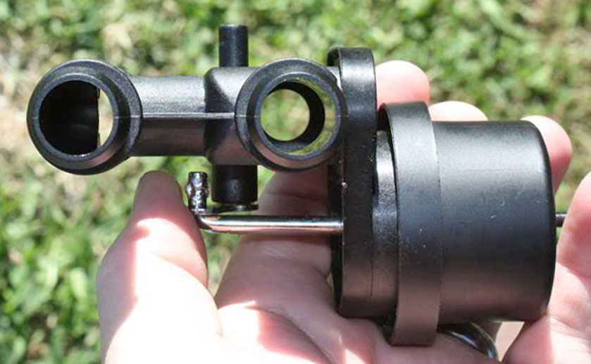 Other 4-port bypass valves. You can also find manual cable actuated bypass valves. This one is made by Thermotion PN 25-1018 and is offered by Old Air Products. Any cable valve and many electric ones can be made to open partially if that's useful.  This electric valve is from CJ Pony Parts. This can be opened or closed (or partially opened) using a variable adjusting knob. 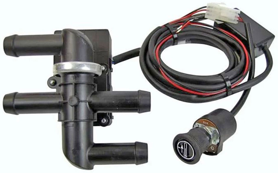 This one above is available at https://www.cjponyparts.com/heater-bypass-valve-kit-servo-controlled-bronco/p/BHV4/ Restomod Air has a similar 4-port valve: https://restomodair.com/shopproducts/4-way-electronic-bypass-water-valve-kit/ Water Pump REAR Port. or skip to next section: Water Pump TOP Port. If your modifications involve deleting the heater return pipe going to the raer water pump port, then you may find it necessary to block off that rear port. A blocking plug like this below can be sourced or created. This plug below was a 2-piece part made by Volvo to fit early or later water pumps. It's a tapered rubber plug with a steel retainer to hold it in. The rubber plug insert is PN 418571. The cover plate is PN 1219915. If Volvo parts are not available, a plug could be made by using the end of an old water pump pipe and then sealing it off. Or there are tapered/conical rubber plugs available in many different sizes online if you want to look into creating your own. 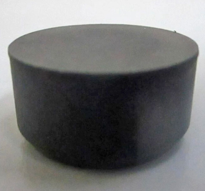 This plug was commonly used for marine engines, as shown on this Volvo Penta pump PN 1378809 below for AQ131 (same as a B230 pump). 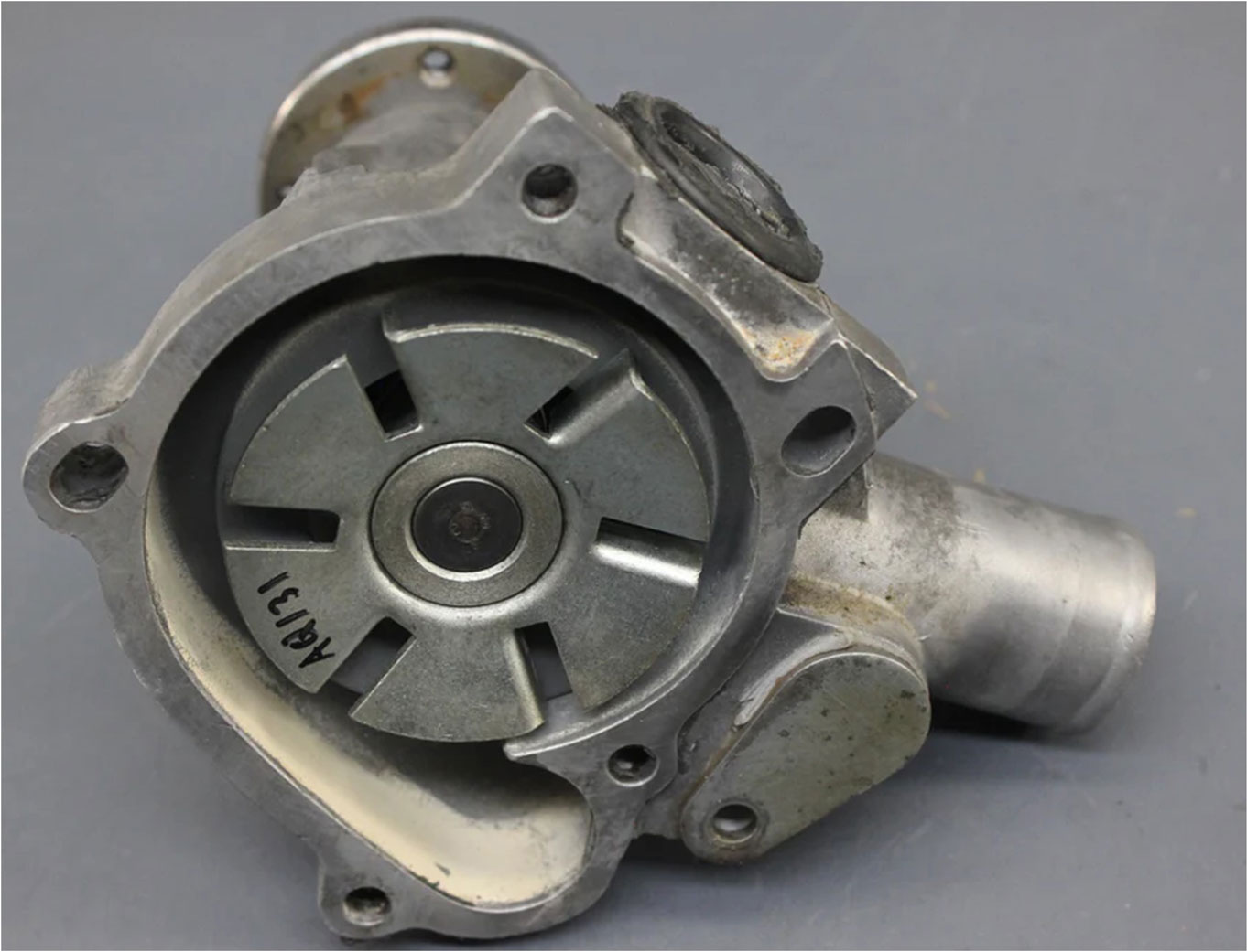 Did racers block off this rear port in Group A 240 Turbos? NO, they did not. Because they added one of these. GO HERE FOR MORE. 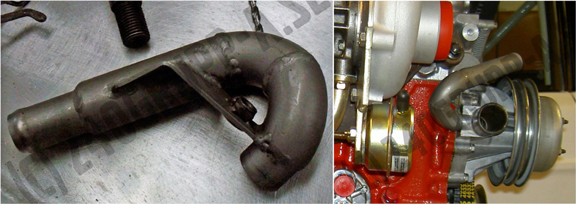
These photos came from Björn Ohlson's 240 Grupp-A page https://240grupp-a.se/kylning/. If you need dimensions of this back port, here are some photos below. Dimensions are the same for all pumps. 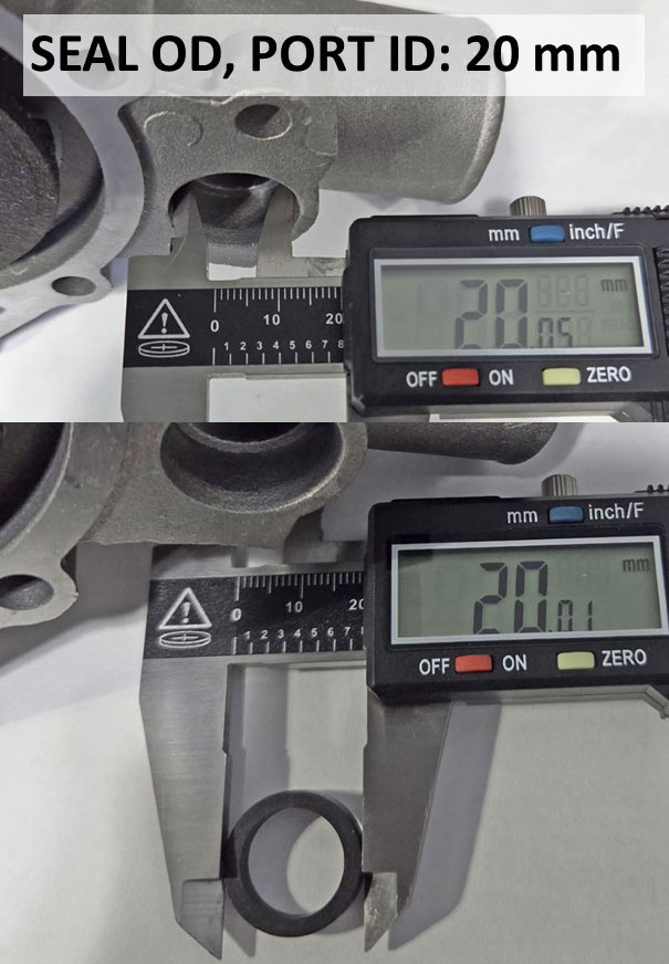 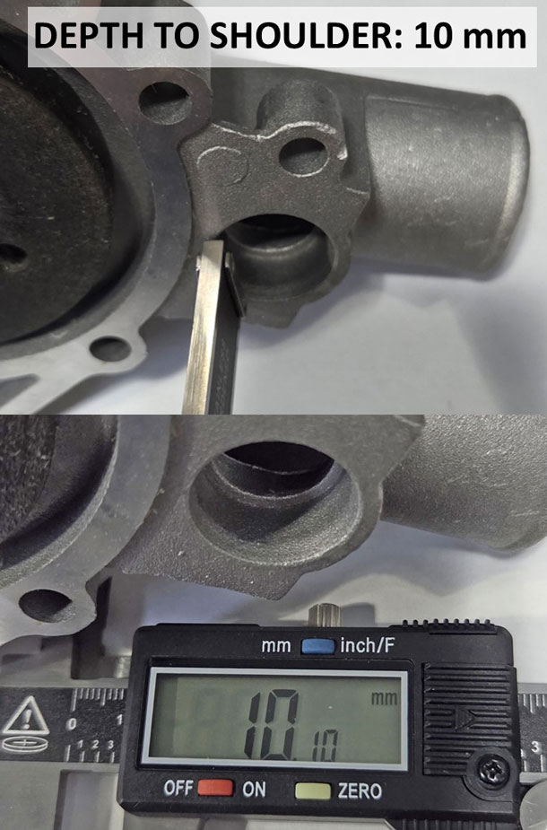 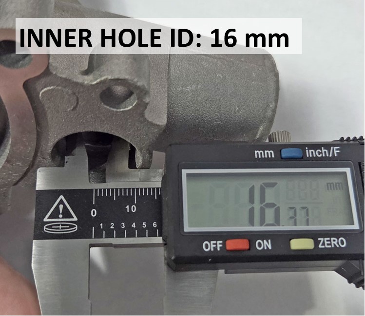 Questions about the Water Pump TOP PORT. or skip to next section: Water Pump Comparison. Before I began studying this closely, I had assumed the water pump TOP PORT (#4 below) flowed out of the pump and up into the cylinder head. Apparently lots of other people had this assumption. This is incorrect. The water pump top port is a suction port and it flows down from the cylinder head. Volvo refers to this #4 port as a BYPASS in manuals. It's called a bypass because it bypasses the thermostat when the thermostat is closed, so water entering the head during warm up can still leave the head. If you want to see more about this see THERMOSTAT FUNCTION.   If you need to be convinced, here are some images of a genuine Volvo B230 water pump (PN 3547559). You can see there is a wall separating the impeller chamber from the top port, rear port and the main inlet. This means the top port, rear port and the main inlet are all SUCTION PORTS. The only outflow or pressure port on this pump is the area immediately surrounding the impeller, which directs coolant into the HOLE on the front of the engine block.  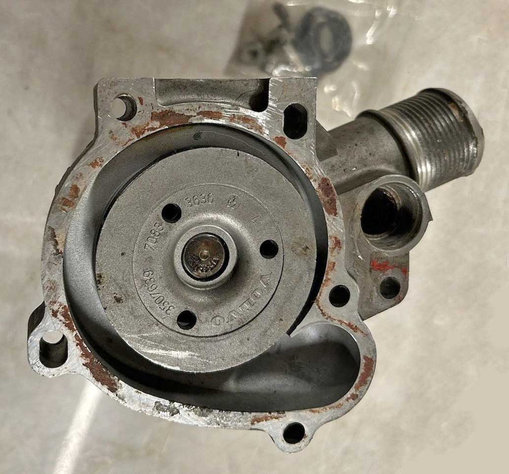 Comparing a B21/B23 pump to a B230 pump. or skip to next section: Thermostat. B21, B23: PN 270681. B230 1985-93: PN 271975, 271830, 271275, 270559, 1326342 Other than the bolt pattern being different, the easiest way to quickly identify which is which is the location of the bolt hole for the heater return pipe. The hole on an early pump is up high. The hole on a later pump is down low.  Here's the hole in front of the block. This hole leads to the water jacket and up to the coolant passages between the block and cylinder head. There's also a second smaller hole up and to the right. I think that may be an air bleed to help eliminate air in the pump impeller chamber and ensure the pump gets PRIMED. 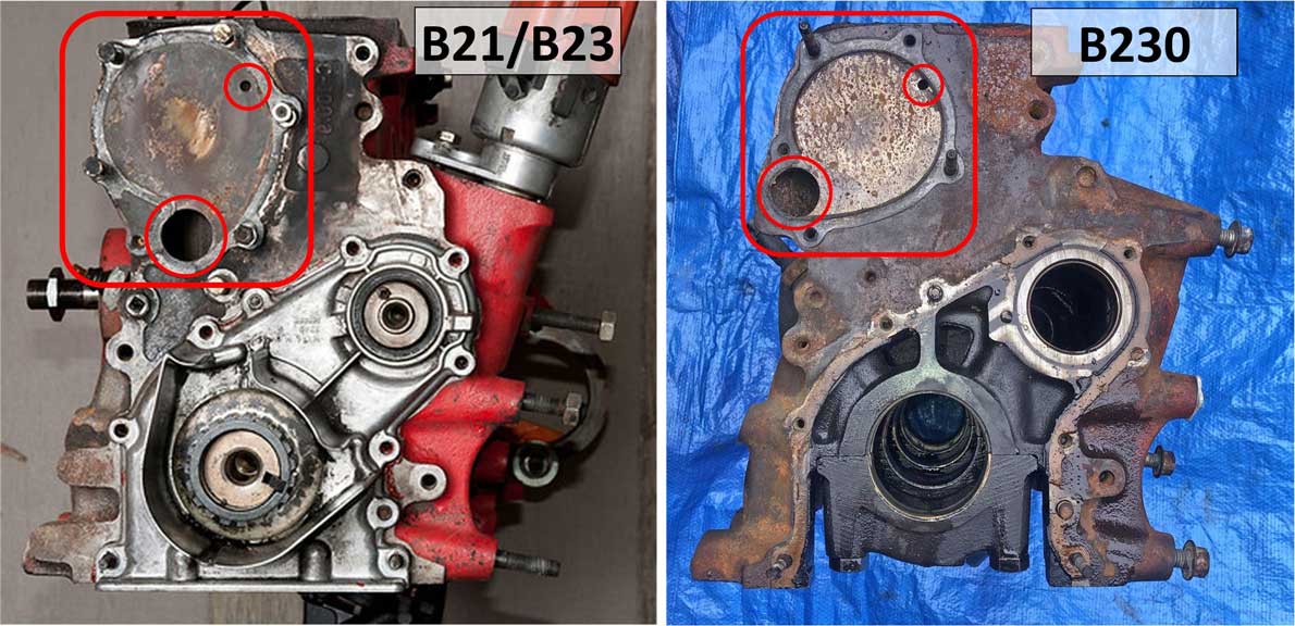 How big is that block coolant passage hole above? I've seen some reference to about 33 mm (about 1.25 inches). I think that may be WRONG. The below measurement I took from a B21 water pump suggests 27.5 mm. 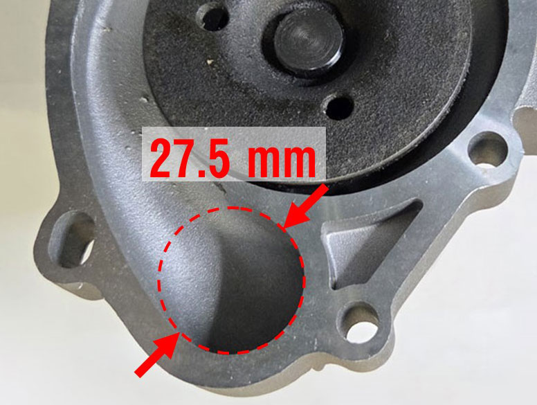 Comparing different IMPELLERS: GMB versus Hepu Pump. Art Benstein wrote a comparison page at https://cleanflametrap.com/wasserpumpen.html. The more solid Hepu impeller is considered to be the closest to what came on a factory Volvo pump. Over the years the general opinion has been that the Hepu was better than an open blade impeller. Is it better? I don't know. GMB is a Japanese company and pumps are made in Japan, South Korea and Thailand. Hepu pumps are made in Germany. 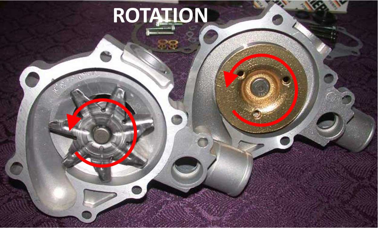 Understanding how a Volvo water pump works was important in my curious mind. It's a centrifugal pump, which is very unlike a positive displacement pump. A positive displacement pump can use sprockets or pistons to draw fluid in and then push it out. These work well if high pressure is needed. A good example of a positive displacement pump is the oil pump in your engine, which has sprockets to pressurize oil. A centrifugal pump uses an impeller to spin the fluid outward against the outer walls of the impeller chamber. The impeller does not push fluid as you would imagine a propeller can. The impeller can push fluid at various speeds with less risk of over-pressurizing, but it becomes very important to make sure any and all air pockets are eliminated. A centrifugal impeller cannot create a vacuum or suction in absence of liquid. It must be "primed". This type of pump will not move or suck coolant if the impeller is dry. Watch the video. Centrifugal Pump Basics https://www.youtube.com/watch?v=Vhc-hEjh12I Understanding Thermostat Function. or skip to next section: Water Pump Pulleys. This image comes from TP30163, Engines 240 1975-85, page 82. 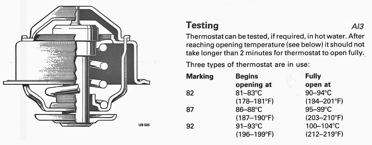 Volvo thermostat part numbers: 71° C (160° F): (non-Volvo, 273460/71); 82° C (180° F) PN 273460; 87° C (189° F) PN 273459; 92° C (197° F) PN 273307. Here are some images below showing the B21/B23 or B230 thermostat and the thermostat port where it gets mounted on the head. Once coolant enters the engine block from the pump, it travels up into the cylinder head through the coolant passages between the block and head. Once in the head, it circulates and eventually exits through the thermostat and out to the top radiator hose. NOTE the bleed valve near my thumb below should be positioned to about 12 o'clock to promote venting of trapped air in the head. 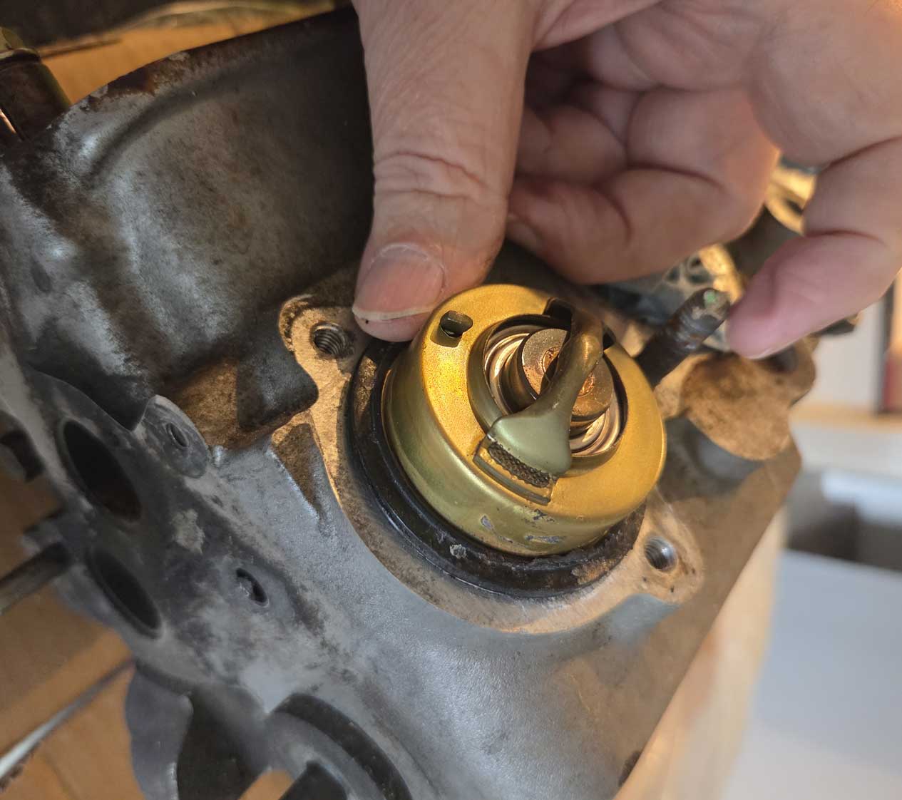 Below we can see the thermostat port is divided inside. There are two separate channels, a center channel and a right channel. The RIGHT CHANNEL leads to the head main cooling jacket. The CENTER CHANNEL goes down to the port on the bottom front of the head. This is the port which seals the head against the top of the water pump. 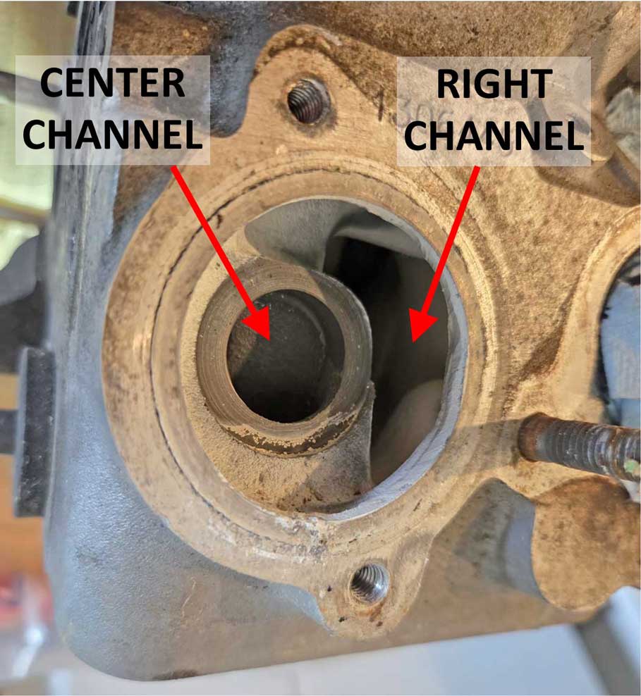 To satisfy my curiosity, I injected water though this center channel, which confirmed what I thought. And in the photo below I also shined a flashlight up into that bottom port, which can be seen shining through from the top.
Volvo refers to this bottom front head port as a BYPASS. It's called a bypass because it bypasses the thermostat when the thermostat is closed (only when it's closed). I took a few measurements of the thermostat port. The center channel port has a flat surface which is about 19 mm below the head surface. That'll be explained next. 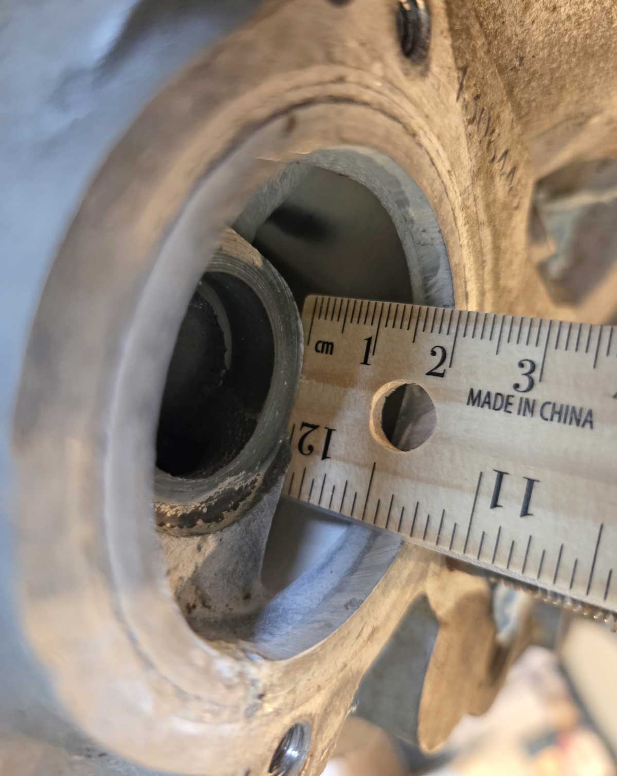 Let's go back to the thermostat. That plunger in the center is what closes off coolant until the thermostat heats up and opens. These photos below show it upside-down. On the part that points toward the head there's a flat round disc, which is somewhat spring-mounted. When installed, this disc points directly at the center channel port mentioned previously. When the thermostat is COLD (like this photo), that disc sits about 10 mm below the head surface and about 9-10 mm away from closing off the center channel port. At this cold temperature the CLOSED thermostat will allow coolant to flow through the center channel and down into the water pump to be recirculated. This recirculation continues during initial warm-up. 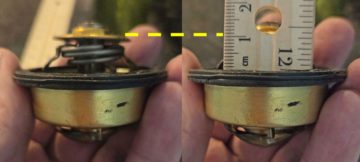 For these images I dropped the thermostat into hot water. As the temperature approaches the set open point, the plunger opens and also that spring-mounted disc extends out to a new position. As it extends out, it will eventually close off the center channel. 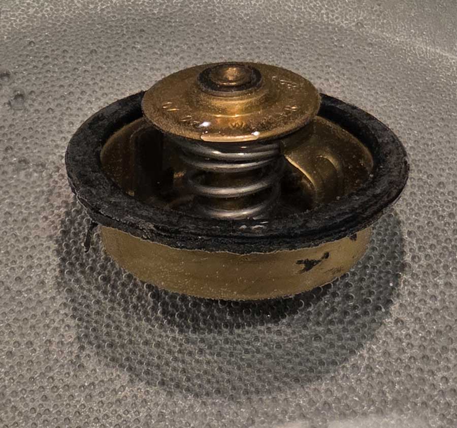 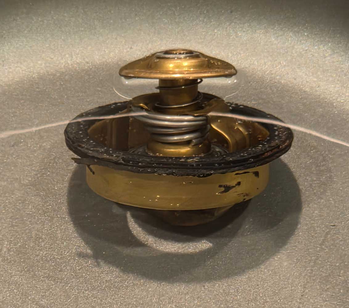 Here's an image BELOW of the plunger as it becomes HOT and OPEN, which allows coolant to flow out of the head into the top radiator hose. 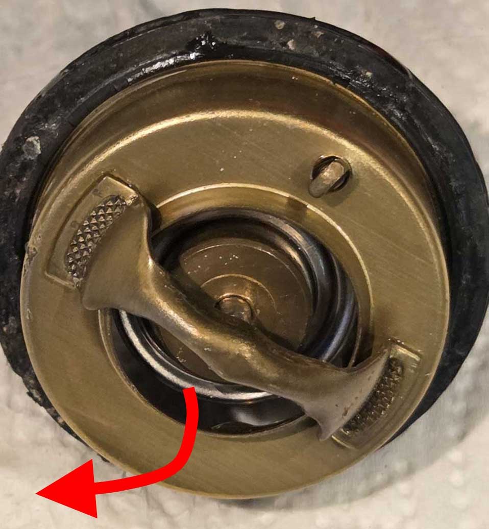 In summary, when the engine is COLD and the thermostat is CLOSED, coolant freely flows through the #4 PORT and into the pump, where it can be recirculated. Volvo refers to this port as a BYPASS in service manuals. When the engine is WARM and the thermostat is OPEN, the #4 exit is CLOSED OFF by the thermostat disc sealing the center channel closed. So when warm, all coolant flowing out of the head comes out through the thermostat and only the thermostat, unless of course some flow is also allowed out of the heater hose port at the back of the head. 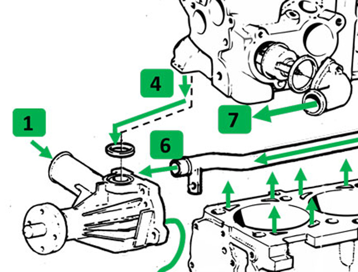 Relevant Links: https://turbobricks.com/index.php?threads/7-9-updated-heater-control-valve.246617/ https://turbobricks.com/index.php?threads/8v-b230-cooling-system-modification.121189/ https://cleanflametrap.com/wasserpumpen.html https://240grupp-a.se/ Relevant General Cooling System Information Cooling System Basics: https://www.c1pulleys.com/pages/cooling-system-basics The Cooling Bible: http://www.billavista.com/tech/Articles/Cooling_Bible/index.html B21, B23, B230 Water Pump Pulleys. or skip to next section: Group A Cylinder Head Cooling. Early water pump pulleys for a 4 cylinder (1976-1984) are found as only one part number and one size. These are slightly smaller than the larger B230 pulley. The B21/B23 pulley can be identified by its lack of reinforced metal (as shown below). It's believed the lack of reinforcement might have contributed to some failures, possibly if the fan belts were overly tightened (more failure info HERE). This could be why the B230 pulleys were revised with reinforcement when they were introduced in 1985. The B230 pulley below has a 138 mm diameter. This large size was generally fitted to non-turbo 4-cylinders (and the smaller pulley is further below). 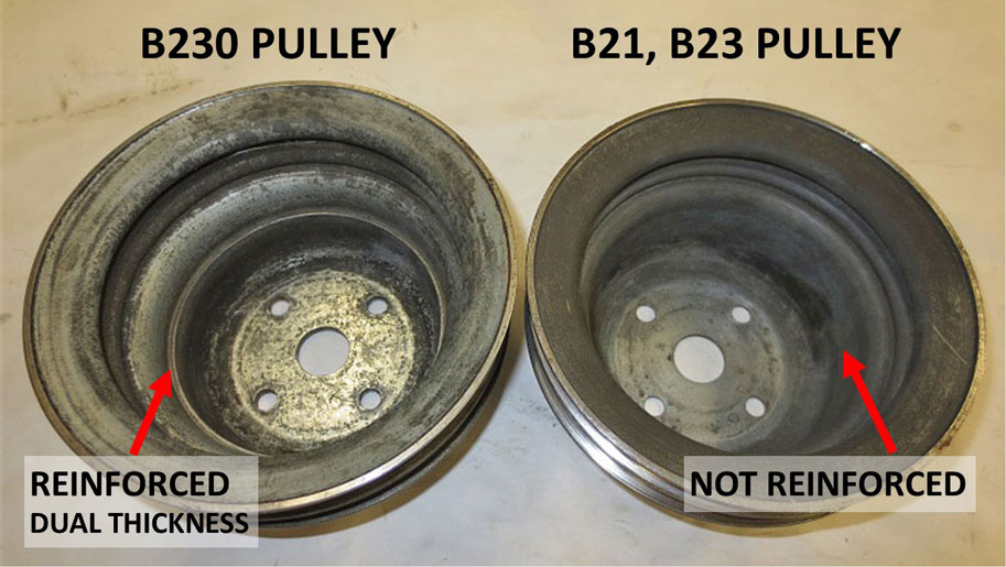 Above photo taken from https://turbobricks.com/index.php?threads/differences-in-water-pump-pulleys-b21-b230.323223/, photo modified by me. Beginning in 1985 for B230FT turbo engines, Volvo installed a smaller pulley with a 117 mm diameter. This one was reinforced too. It's thought the smaller pulley was intended to improve engine cooling at idle on turbo cars by spinning the pump faster (18% gain). There are some opinions (GO HERE FOR MORE) that the higher pump speed can promote impeller cavitation at elevated RPMs (discussion HERE), potentially reducing cooling capacity, also possibly at sustained higher RPM highway cruising (above 3200 RPM). Also there are opinions that the smaller pulley has potentially contributed to coolant over-pressurization at very high RPMS, sometimes being blamed for popping freeze plugs. 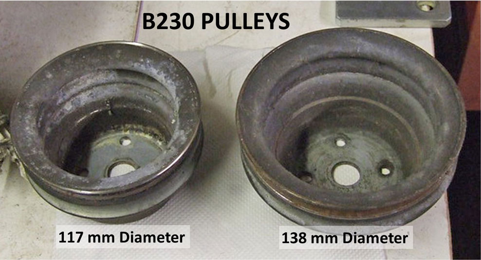 Above photo taken from https://turbobricks.com/index.php?threads/water-pump-pulley-diameters.374577/, photo modified by me. Early and later pulleys are mostly interchangeable and the belt grooves are in the same place. The exception is the SMALL later pulley will not fit on an early water pump, because the early style pump structure interferes with the inside of the small pulley.
Relevant Links or Discussion Threads https://240grupp-a.se/ https://turbobricks.com/index.php?threads/water-pump-pulley-diameters.374577/ https://turbobricks.com/index.php?threads/confirming-size-differences.367875/ https://turbobricks.com/index.php?threads/water-pump-pulley-compatibility.363061/ https://turbobricks.com/index.php?threads/differences-in-water-pump-pulleys-b21-b230.323223/ https://turbobricks.com/index.php?threads/cooling-system-changes-for-high-rpm-use.218895/ Group A Cylinder Head Cooling Hole Modification. or skip to next section: Group A Holes Video. This cylinder head modification has been around for a long time and was reportedly used for ETCC racing Volvo 240s in the 1980s. I don't think this mod is fully understood by us enthusiasts. And I don't know if we'll ever get a satisfactory explanation of what it actually improves or to what degree. Most explanations are vague (including the below video) which discusses using a head gasket as a template to locate FIVE NEW HOLES holes to be drilled for better cooling (shown in RED BELOW). Three of those new holes were shown to be drilled longitudinally along the EXHAUST SIDE. 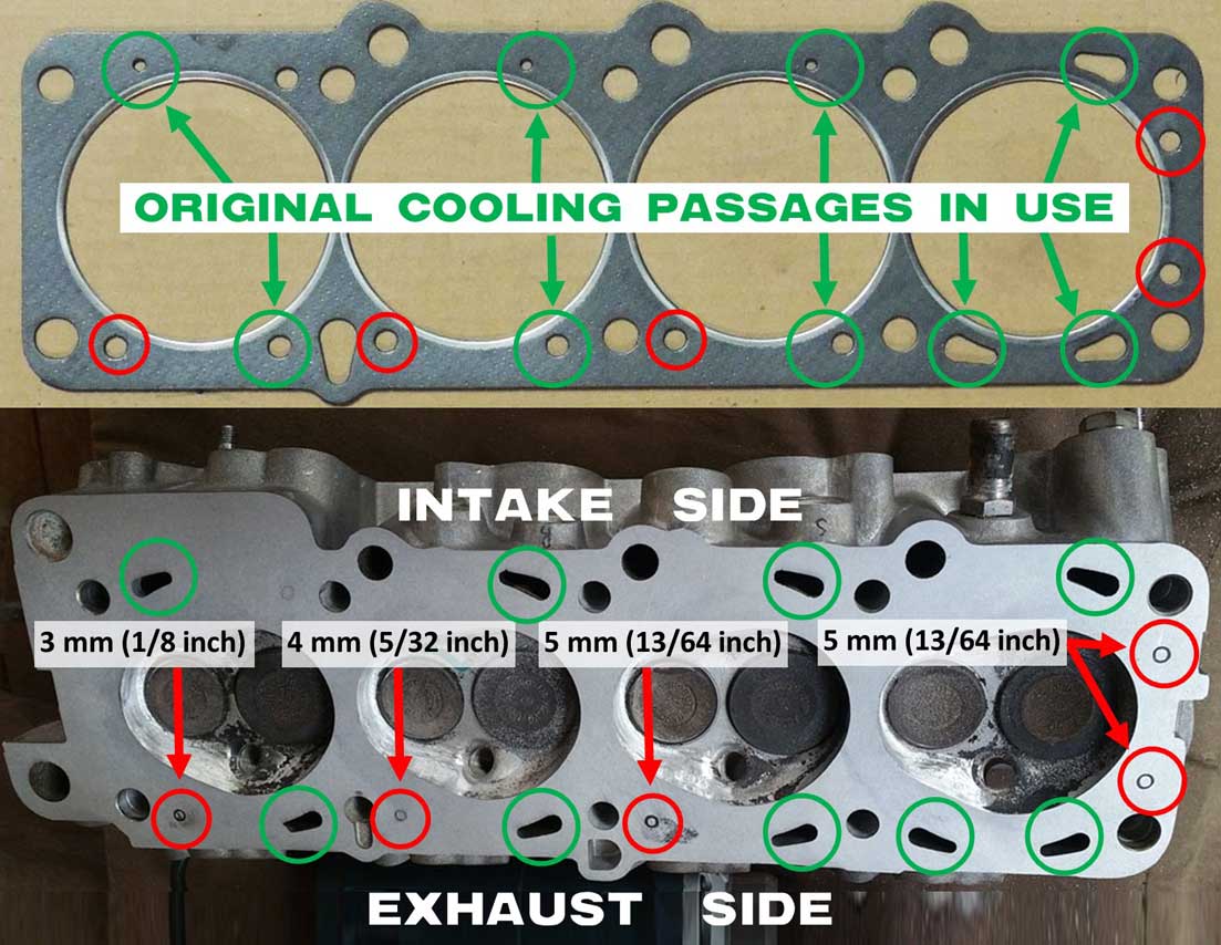 The above cylinder head image is from https://ozvolvo.org/d/9617-530-531-head-porting-and-polishing/19. Photo emphasis was added, including the hole drill size info, which was taken from the BELOW VIDEO. The same hole sizes are also referenced in Stoni's World head work page: https://www.stonis-world.com/headwork.html. Stoni's page states the reason for the different drill diameters is to hold the flow balance in the head. Improved cooling happens due to the increased mass. NOTE OF INTEREST: There is ONE EXTRA HOLE marked on this head ABOVE (not yet drilled). It's on the INTAKE side of cylinder #1. It's hard to see at first. Coincidentally this hole is also present in a head gasket. Most modifications like this seem to add only 5 holes. This extra hole suggests some people have been drilling 6 holes. Further down you see that Peter Linssen also added this 6th hole to his racing head. A compelling question came up in my mind concerning the three holes along one side. Some of the old 240 Turbo Group A images clearly show these three holes are drilled on the INTAKE side (LIKE the BELOW image), not the EXHAUST side as seen ABOVE. Is there an explanation? So far none has been found for a preference for either side. At the same time virtually all other images I have seen, including the ABOVE image, show these holes drilled on the EXHAUST side. Putting holes along the INTAKE side might be slightly less intuitive, because it doesn't appear any head gaskets have all of those holes on the INTAKE side. For example, this image BELOW was posted in the 240 Grupp-A page https://240grupp-a.se/kylning/ and it shows holes drilled on the INTAKE side. I wonder if there's an explanation. Does it matter? 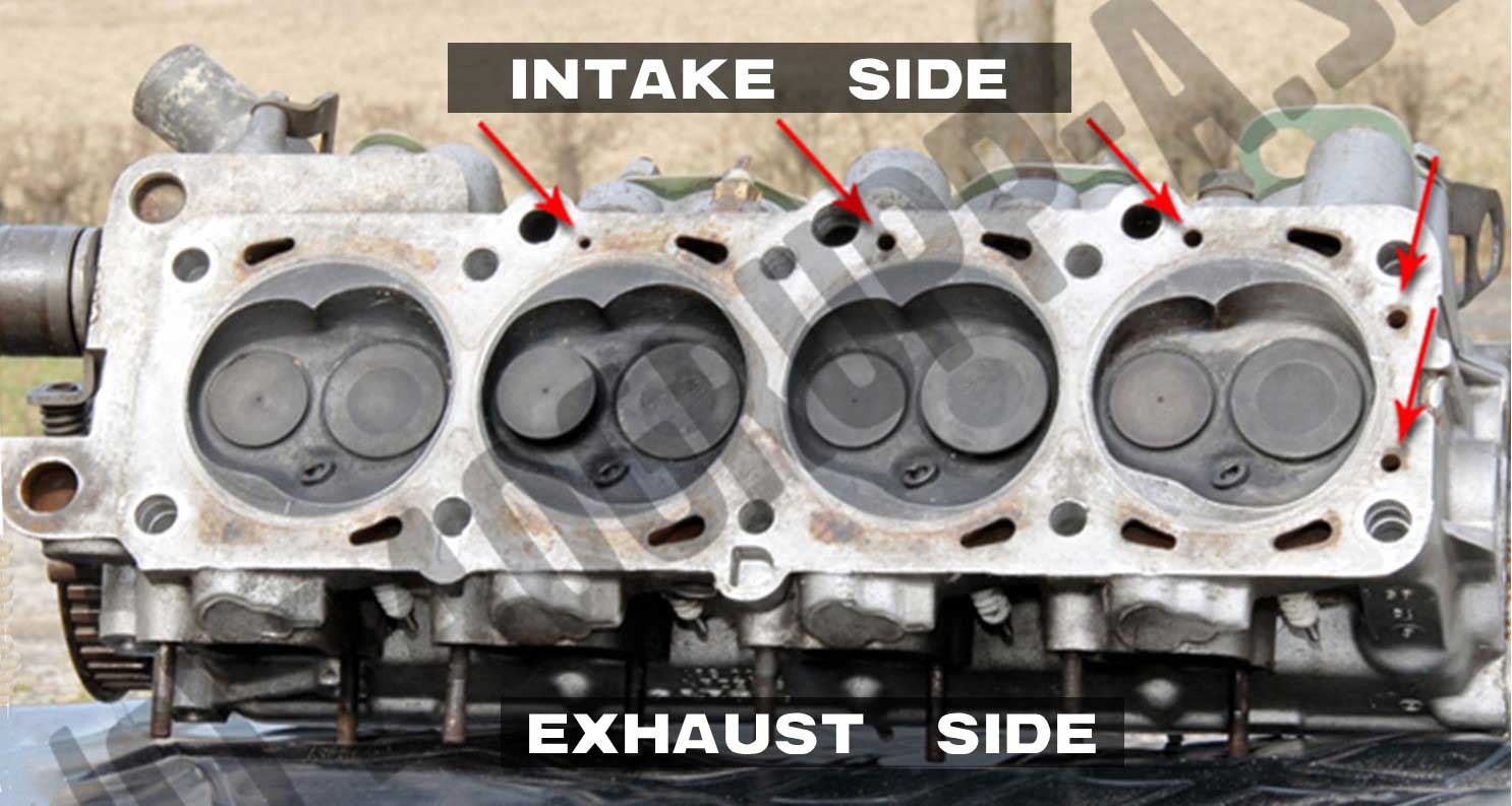 If I was to offer my uneducated opinion, I think I would choose to drill these holes on the HOTTER EXHAUST side, simply because that's where the head gasket holes are and the exhaust side is obviously a lot hotter anyway. But maybe someone thought because of the engine tilt (or who knows), the holes might be better in the HIGHER ELEVATION INTAKE side? Or maybe they flipped a coin. I welcome your comments. This short VIDEO below offers an explanation of how these holes can be added. or skip to next section: Group A 240 Owner's Manual. Group A 240T Head Cooling Mod. https://www.youtube.com/shorts/qqn_xvRclG0
Relevant Links or Discussion threads: https://turbobricks.com/index.php?threads/8v-b230-cooling-system-modification.121189/ https://ozvolvo.org/d/9617-530-531-head-porting-and-polishing/19 https://www.stonis-world.com/headwork.html https://turbobricks.com/index.php?threads/are-people-still-doing-the-grpa-cooling-mod.382897/ https://240grupp-a.se/kylning/ This image below has been around for a long time. It's from Bilsport Magazine Nr 10, 2001, page 27 (in Swedish). It very lightly discusses adding the Group A cooling holes (on the exhaust side in this image). I added an English interpretation below, however it offers very little help.
This is Page 14 from the Volvo 240T Group-A Owner's Manual, by Richard Prince. or skip to next section: Grp A U-Bend Pipe. Note that the image in this page apparently originally came from Björn Ohlson's 240 Grupp-A page. It shows the three holes drilled along the INTAKE side. A link to the full Group A Manual is a bit further below CLICK HERE. 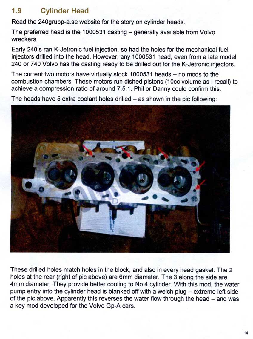 The above Cylinder Head page mentions that Group A heads were ALSO modified by blocking off the water pump port, by inserting a "welch" plug in the head. A welch plug is the same as a freeze plug. Also it speculates that this reverses the flow through the head. NO! It does NOT reverse the flow. Blocking this port simply stops coolant from flowing down from the head to the water pump top port. This downward flow was a factory function during warm-up, used when the thermostat was cold and closed. Installing a "welch" plug as mentioned can be a logical modification for a race car that no longer needs the factory warm-up function or a traditional thermostat. This port in the head was also detailed in a previous section. In a factory engine, coolant flows from this port down into the water pump when the engine is cold. Then this flow becomes closed off by the thermostat when it gets warm (More detailed thermostat function explanation CLICK HERE). 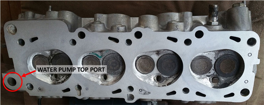 These comparison photos BELOW (also found in Björn Ohlson's 240 Grupp-A page https://240grupp-a.se/kylning/) show that some serious porting was done to open or blend the two thermostat channels. 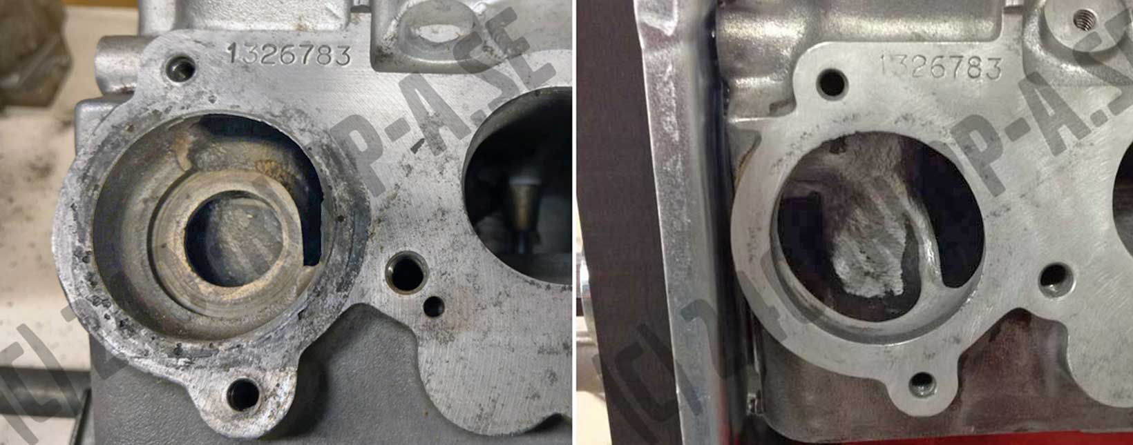 Group A Mod. U-Bend Pipe for the Water Pump. or skip to next section: More Related Performance Cooling. These images BELOW were found in Björn Ohlson's 240 Grupp-A technology page at https://240grupp-a.se/kylning/. They show a custom U-bend pipe made for a Group A 240 Turbo. It was inserted into the water pump REAR port where the heater/coolant return pipe would normally be on a factory engine. Björn's page only describes the pipe's purpose as "for increased water flow." 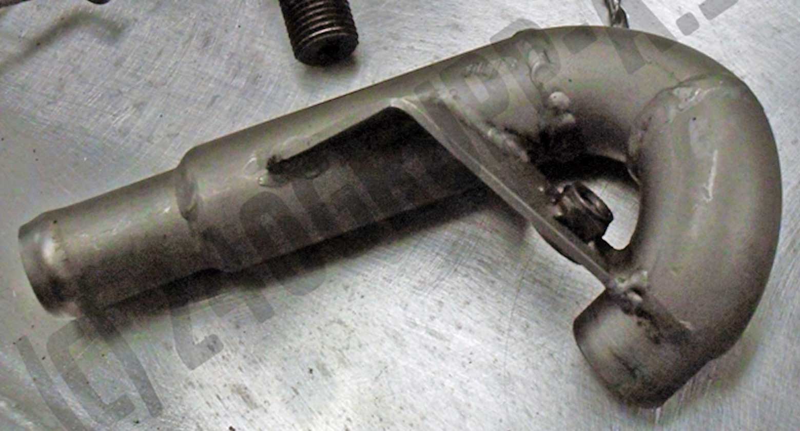 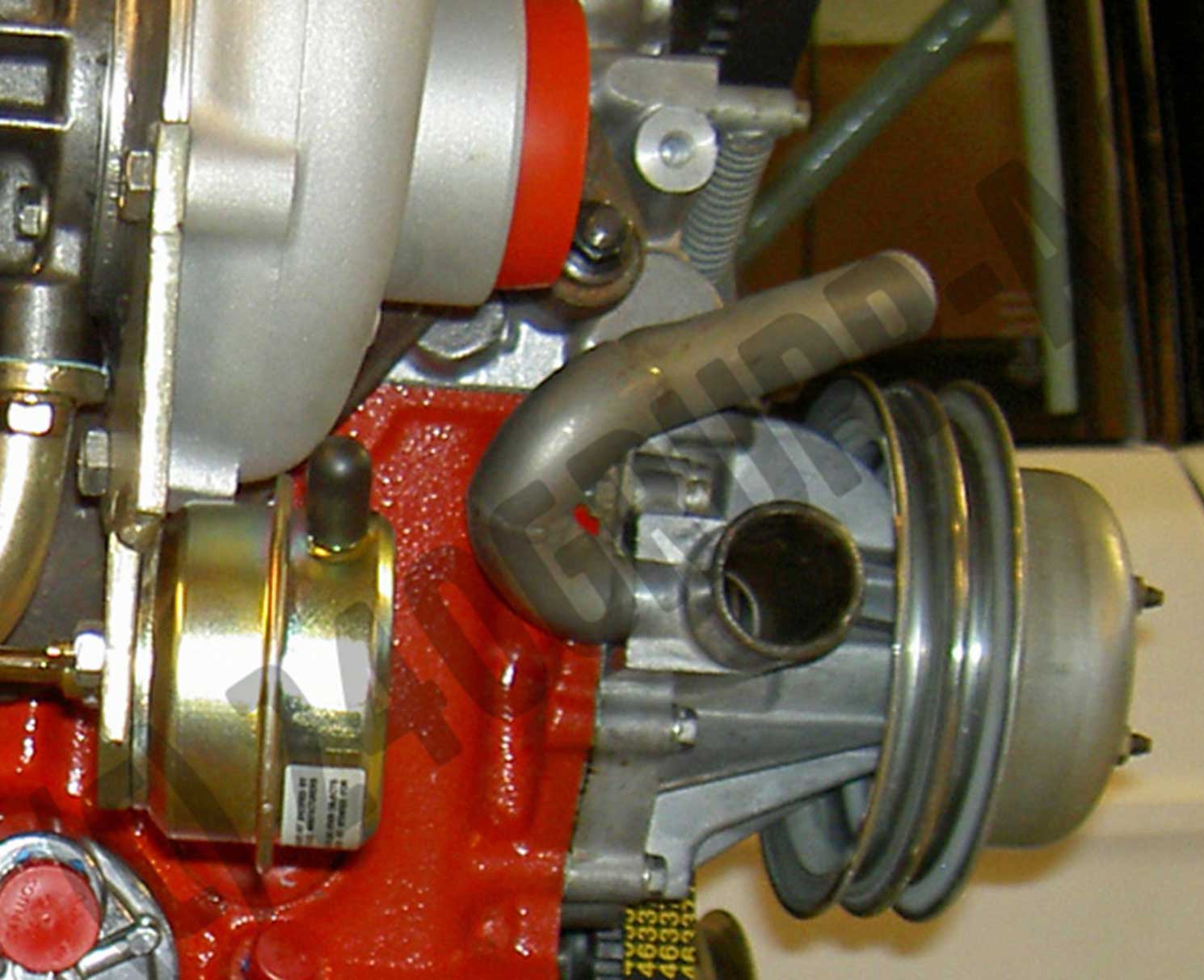 In an upcoming photo BELOW, you can see this U-pipe was made to bring water into the water pump rear port from the expansion tank mounted above. When I first saw this, I have to say I was puzzled. I agree that bringing in some extra water from the expansion tank, which comes from the COLD side of the radiator, is a good thing. This pipe looks like it was quite an effort to create. In my limited understanding, it appeared to me that a far easier alternative would have been to add a TEE FITTING (like below) into the lower radiator hose next to the pump inlet. The water would still flow into the same place. I don't know if adding the U-bend pipe makes that extra water flow any better than a TEE fitting could. But it appears only this u-pipe was used in Group A. They never used a TEE fitting that I have seen.  This TEE was made to fit the lower radiator hose, Volvo PN 1378548. If a TEE like this was used and the rear water pump port no longer had a use, the back of the pump could be simply BLOCKED OFF like shown in THIS SECTION. This image shows the U-bend pipe connected to the expansion tank above. Image BELOW from Björn Ohlson's 240 Grupp-A page at https://240grupp-a.se/kylning/. 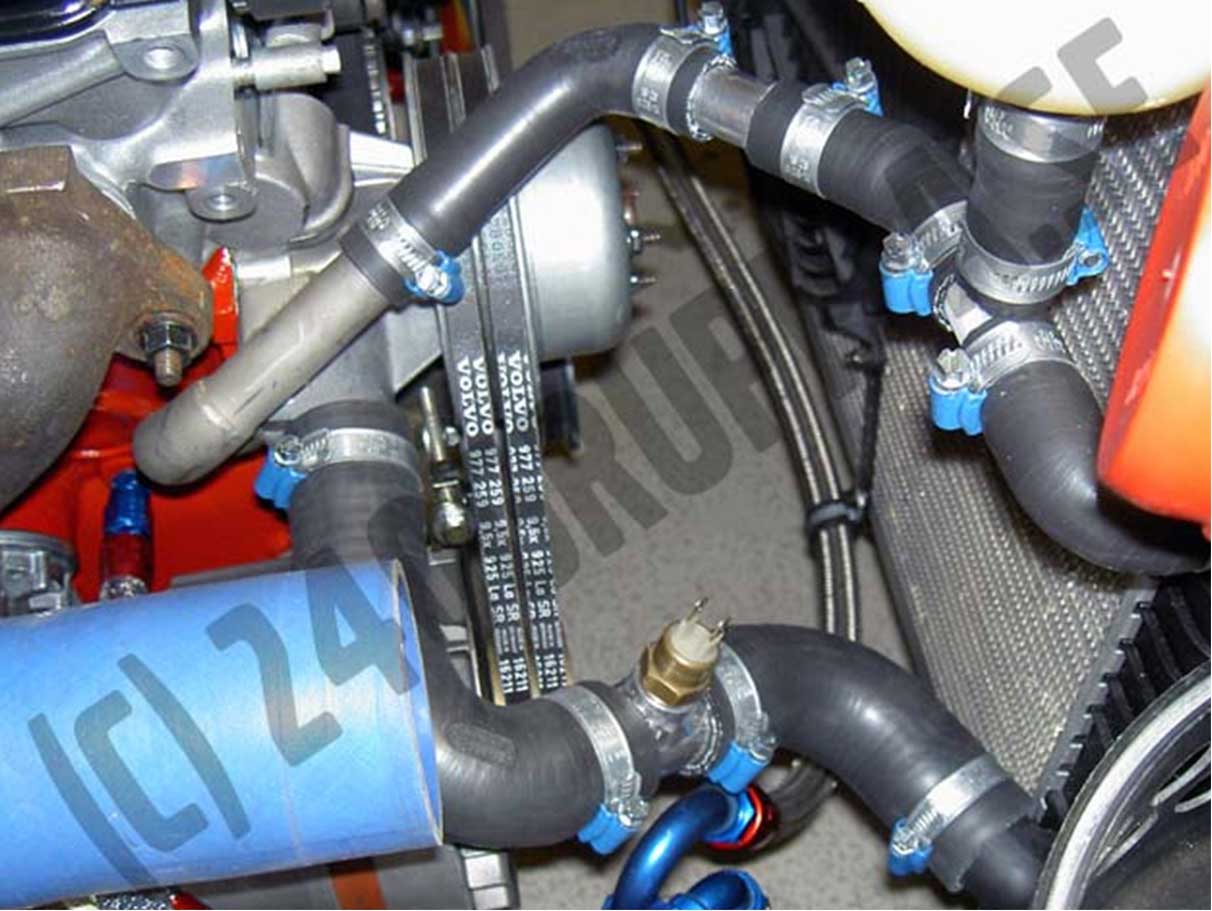 I searched through archives of 240 Group A Volvo photos. A U-pipe like this has been found in photos of nearly every Group A 240 I've been able to find photos of, so it was obviously well-regarded as a worthwhile modification by nearly all teams. This makes me think maybe someone developed technical information about this and the Group A 240 teams had access to it. Otherwise I don't know how this pipe came to be so common. I have NOT found this pipe mentioned in any FISA 240 homologation documents, in any Volvo R-Sport Competition catalogs, or in the 240T Group A Owner's manual. The origin of this pipe is a total mystery to me. What was its origin and did it offer any cooling improvement? This pipe has also been added to a number of replica Group A 240s, such those created by Peggen Andersson and GRC Motors (or GDM Motors) in Belgium around 1999 to 2023 (https://www.hagerty.co.uk/articles/news-articles/volvo-240-flying-brick-replicas-to-storm-the-track/). Then I speculated this pipe might have been made to help REDUCE potential PUMP CAVITATION at high speeds: When the engine runs at high speeds, the water pump spins really fast. If it's too fast, the high speed of the impeller can create a severe drop in pressure which begins at the eye of the impeller. Vapor bubbles begin forming in the impeller chamber and this effect will displace the water (this is CAVITATION). Because vapor bubbles DON'T transfer heat well and it makes it hard for water to get pushed through it's circulation, coolant flow drops off severely and engine cooling suffers. Race cars often use ONLY WATER for cooling, because a spill of water on the track is much less of a problem compared to antifreeze. Water has a higher vapor pressure than a 50/50 mix of antifreeze, so a cavitation effect becomes worse with pure water. Since the Volvo water pump has a centrifugal impeller, the impeller must always be fully submerged and well fed to remain efficient. Perhaps high speed impeller cavitation was a recognized problem by Volvo or by racing teams. Group A engines were given SMALLER DIAMETER CRANKSHAFT PULLEYS to slow water pump speed (visible in https://240grupp-a.se/motor/). Perhaps this U-bend pipe was a way to improve water supply to the pump impeller; to ensure the pump is well fed from an ADDITIONAL SOURCE ABOVE THE PUMP, rather than relying on only the SUCTION OF WATER up through the lower radiator hose. Apparently, it turns out this "special" U-pipe actually does very little. I was able to contact Peggen Andersson, who was directly involved in Volvo ETCC Group A racing. He was familiar with this pipe and he was not aware if there was ever a cooling benefit. He said the pipe offered a faster way to fill the engine with water. As a favor, he contacted a few others he knew who were more involved in the technical side and they confirmed that faster filling was the only benefit. Peggen confirmed the cooling system improvement modifications were limited to a larger radiator, cylinder head cooling channel modifications, a smaller crank pulley to slow the water pump, and there were some modifications to the water pump, which he didn't have details on. This photo BELOW shows another U-bend pipe arrangement with the expansion tank much further away near the suspension tower. There are several other locations where the expansion tanks have been seen in photos of these cars. This is a Sportpromotion "LUNA" Group A 240 built by Magnum Racing. 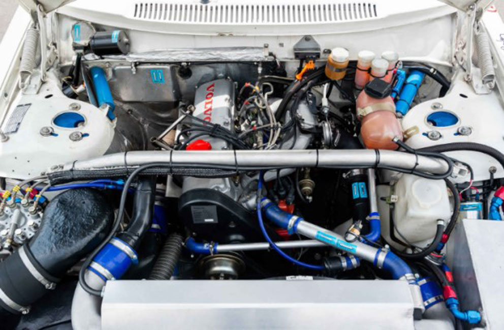 This car BELOW is one of the FOUR Group A 240's contracted by Volvo to be built for the 1985-86 ETCC season. Only two of them still exist. One, built by Magnum Racing, has been seen in the Volvo Museum in Sweden. This one below, built by Volvo Motorsport was reported to have been driven by Ulf Granberg and Anders Olofsson. And in the late 1986 season by Mauro Baldi and Peggen Andersson. The cars were managed for Volvo by RAS Sport in Belgium. The U-bend pipe can be seen if you look closely. I think this car was owned by Peggen Andersson up to about 2017. The current owner is not known. 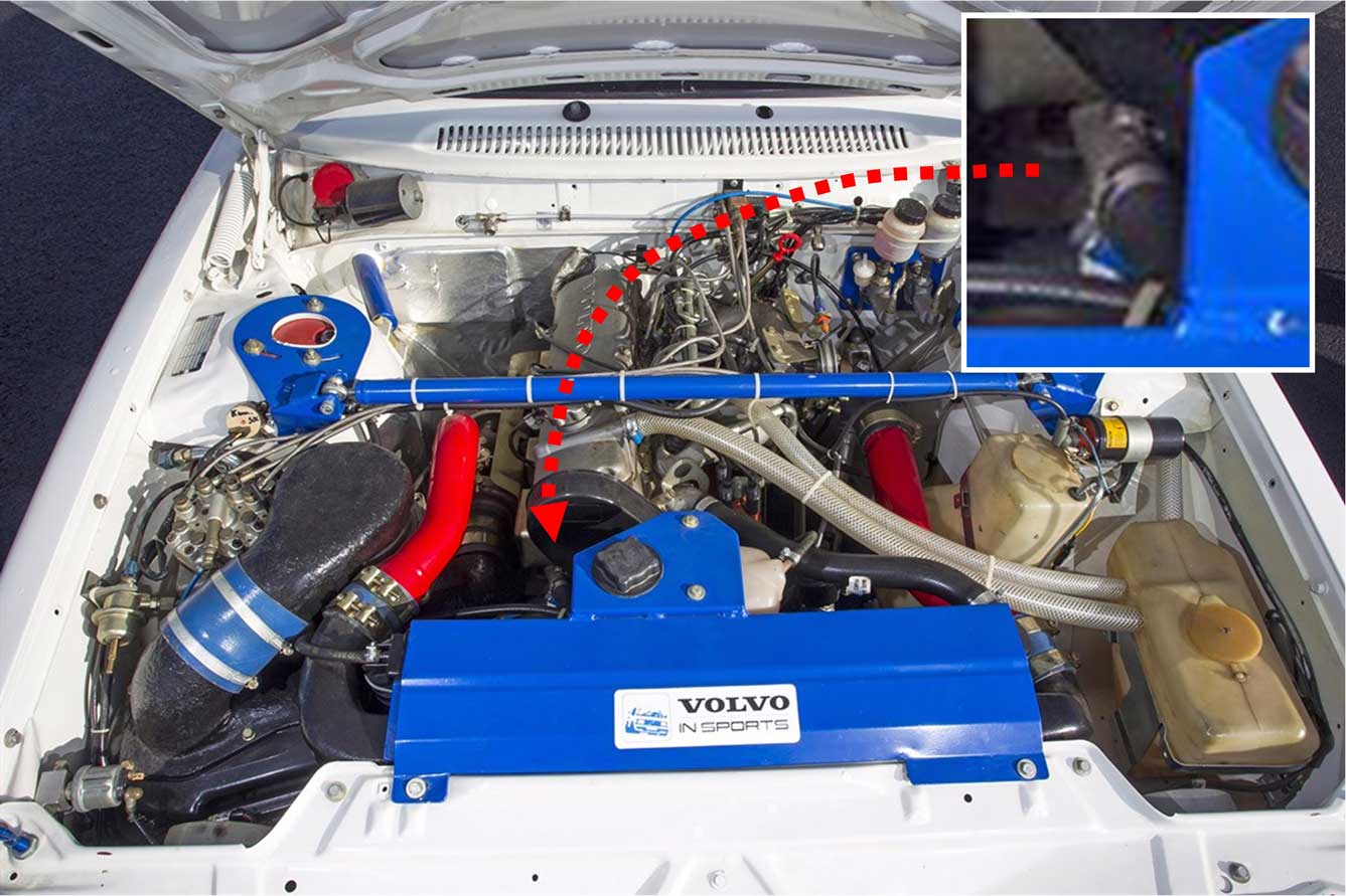 Here's another peek at the U-bend pipe image BELOW. Again the expansion tank water is flowing down to the U-pipe. This photo below shows an RAS Sport (Nordica) 240. 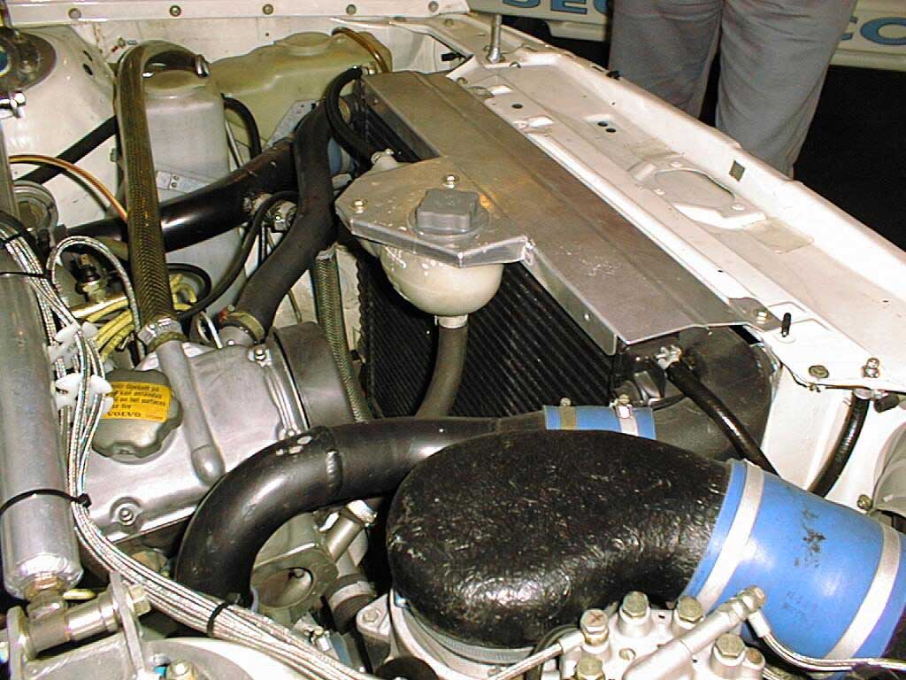 Plus an interesting separate note in these photos: If you notice the small radiator over-flow hose, it's mounted up through the radiator support. I don't know for certain, but it looks like it might have a cap on a valve. With the way this expansion tank is plumbed, filling that tank would not fill the radiator. There is no radiator cap on the radiator or any other fill access without opening the top radiator hose. So perhaps this overflow hose fitting is for topping off the radiator quickly in the pitts? 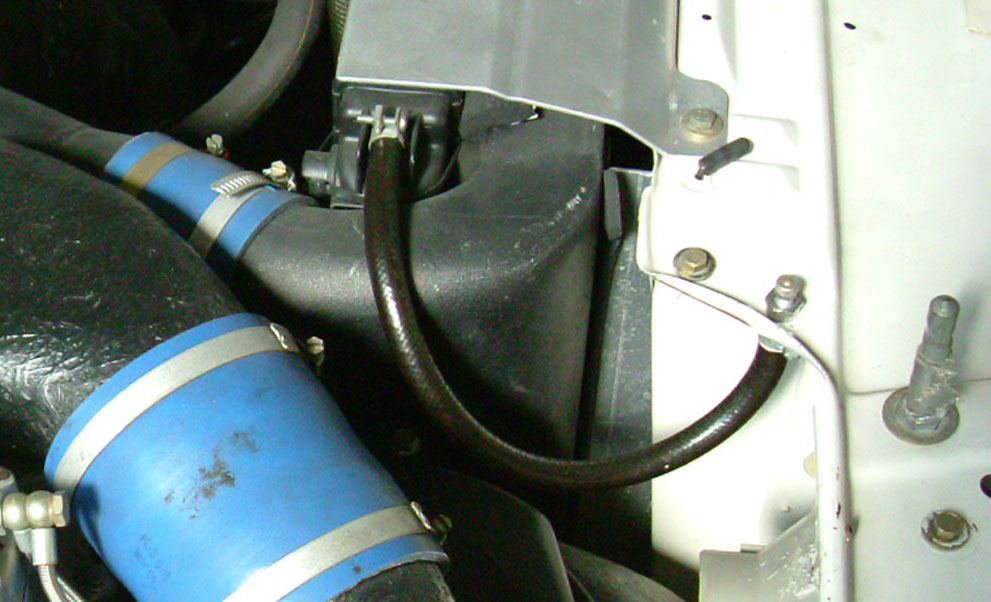 The complete 32 page GROUP-A MANUAL (pdf) by Richard Prince can be found at https://1drv.ms/b/s%21AtjXfjFx5NHNjakt9r9kaL2_GeVI9Q  More Related Performance Cooling Mods. or skip to next section: BCP compared to SCP Heads. Peter Linssen (co-founder of MVP and later owner of The V-Shop in Portland Oregon) owned a 1985 740 Turbo (manual transmission), which was first modded as a powerful daily driver and then years later into a very powerful race car. The second pic below was taken in 2004 at Thunderhill Raceway in Willows, California following the 2004 Davis Volvo Meet.  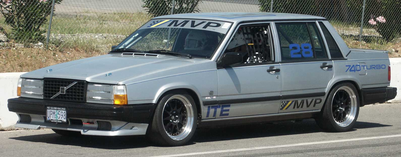 Here it is below during the 2007 Davis Volvo Meet.   Then these pics below were taken at the 2012 iPd Garage Sale. 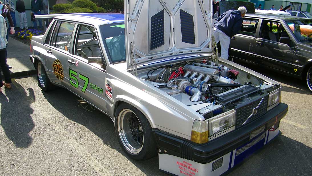 Peter eventually retired years later and sold the car in 2025. More photos and some great commentary can be seen in the Bring a Trailer sale from 2025: https://bringatrailer.com/listing/1985-volvo-740-6/ 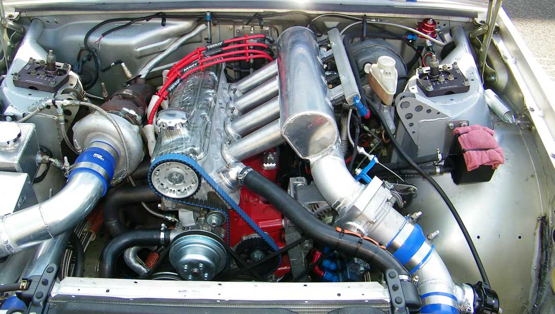 Peter did a lot of experimentation and development with this car so it could stay cool during high speed endurance racing in warm weather while producing 500 hp. One such experiment was described in the below linked 2007 TB discussion thread where the below cylinder head images were shared. The success of this bypass mod is not known to me, but the reason for showing it and for referencing the below TB thread is to share ideas for those who might want to know about experiments like this. We should not be afraid to try new things to see what works for your car. Ignore the internet trolls. 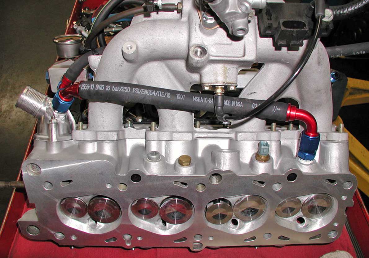 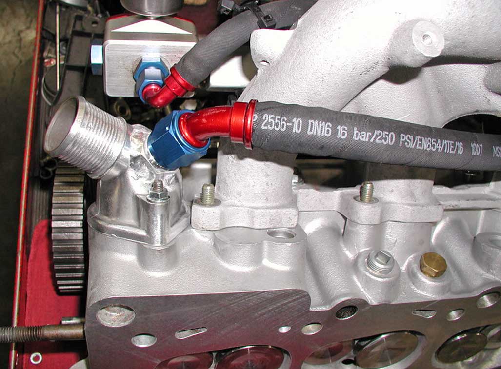 In this discussion thread below, TB member stealthfti mentioned that he had done something similar, except that he had terminated the hose into a "T" or "Y" fitting in the top radiator hose. Stealthfti reported he had tested his modification extensively and he felt STRONGLY that it was a success. NOTE: There are a lot of photos missing in this thread, so reading it will require using your imagination in some places. https://turbobricks.com/index.php?threads/8v-b230-cooling-system-modification.121189/ Perhaps stealthfti's idea of using a "T" or "Y" into the radiator top hose offered a better solution to promote positive flow in the direction it was intended. If you consider how Volvo originally intended that rear heater port on the head to be plumbed, it normally returns coolant to a SUCTION port on the back of the water pump. So we need to think about how mods like this could affect coolant flow. This bypass hose mod Peter did above has not appeared in any later photos of his car. Perhaps Peter abandoned this idea and did something different. Did you spot the Group A holes? You can spot the Group-A cooling holes which were added to this head. TWO holes at the back, THREE holes added along the EXHAUST side, PLUS there's a SIXTH HOLE drilled on the INTAKE side near cylinder #1 intake valve. This extra 6th hole is also found on a head gasket. 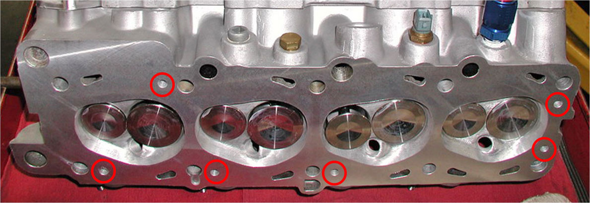 Comparison of a BCP versus SCP head. or skip to next section: Oil or Water Cooled Turbo. Here you can see the difference between a BIG COOLANT PASSAGE (BCP) head and the more desirable SMALL COOLANT PASSAGE (SCP) head. PHOTO: The BCP head at top is a 160 head. The SCP head at bottom is a 530. 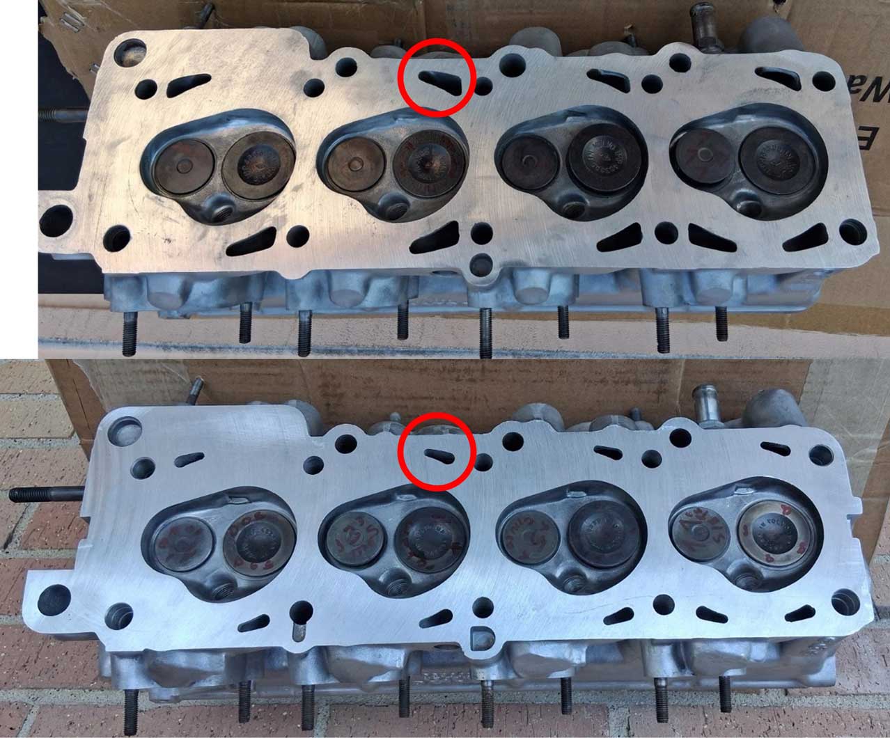 Why is the Small Coolant Passage head considered better? It's considered to be a stronger design, sealing better at the head gasket when under high stress or high boost, and it's potentially less prone to cracking. When did this coolant passage change occur? One Turbobricks member wrote: "I have a 398 BCP head dated 3/3/84... and a 398 SCP head dated 4/12/84." I also have a 398 SCP head I pulled from a Pick-A-Part that is dated 4/4/84. Apparently this change occurred between March 3 and April 4, 1984 (at least for 398 head). Where can you find the date code? It's molded into the head on the exhaust side very close to the back as shown below. The numbers are vertical (Day - Month - Year), i.e.: for a 12 April 1984 head the numbers appear as 12 then 4 then 84 at the bottom. This date code example below is a BCP 160 head with a date of 23/4/83 (23 April 1983). 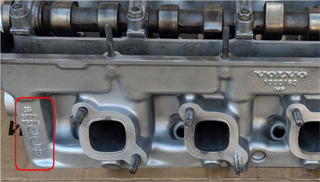 Oil Cooled or Water Cooled Turbocharger? Skip to next section: Turbo Coolant Lines. Here are some example turbochargers. The left turbo is oil cooled. The right turbo is water cooled. On this water cooled turbo the water fitting is a banjo type. 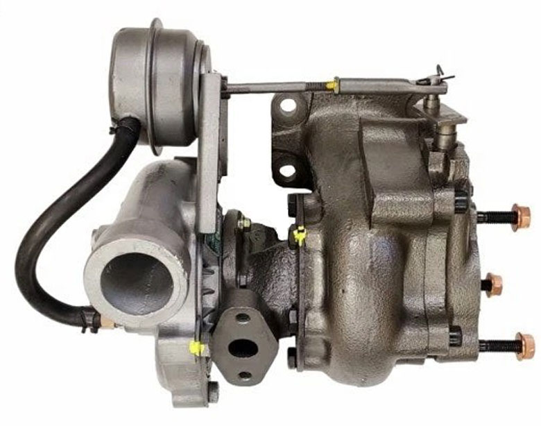 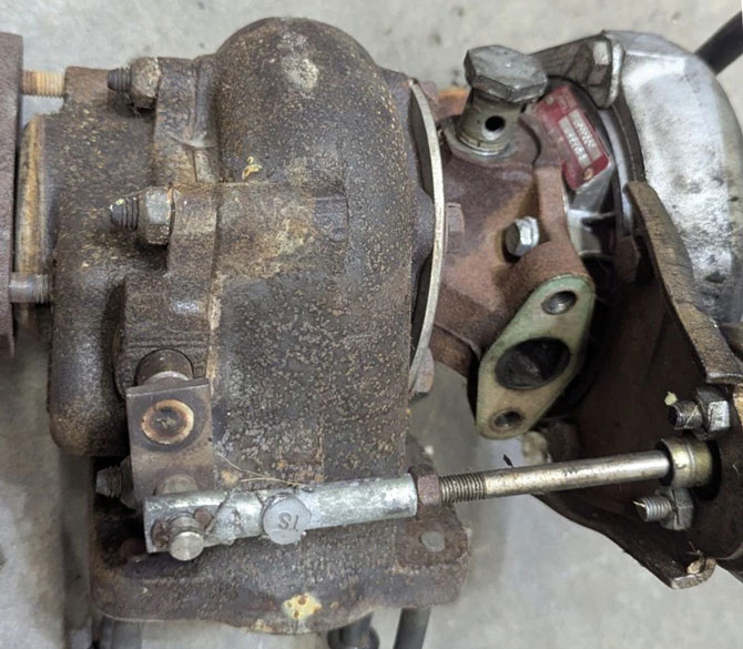 Here are some fairly typical banjo fittings for a water cooled turbo. 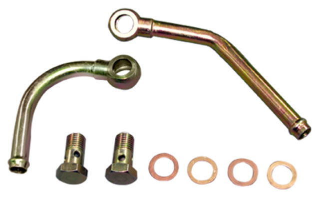 Beginning in 1981, when the Volvo 240 Turbo was introduced, it originally came with an OIL COOLED turbocharger. If a turbo is not water cooled, then it relies on oil circulation to cool it. The truth is all turbos rely on oil circulation for lubrication and oil has cooling properties, so even a water cooled turbo is oil cooled too. Volvo upgraded all 240 Turbos with an oil cooler mounted next to the radiator, which helped cool the oil for the turbo. It was fairly common for an oil cooled turbo to fail prematurely in a 240 Turbo in the 1980s. When turbos were replaced, many of them were upgraded to water cooled types. Most of these retrofits were done at Volvo dealerships. Coolant fittings (pipes) and coolant hoses were added (these are discussed BELOW). These failures don't necessarily mean that an oil cooled turbo is less durable. A turbo can fail for a number of reasons, but there are some potential failure causes that can be attributed to high heat, infrequent oil changes, and oil coking. Oil coking occurs in the hot oil passages when super-heated oil cooks and and then slowly forms hard deposits as it cools off. The problem was made much worse when Volvo owners didn't allow the turbo to cool down before shutting off the engine. Eventually these deposits can build up and choke off oil feed passages and damage bearings inside the turbo. Volvo recommended that drivers never quickly shut off a hot turbocharged engine. Instead they recommended that a turbo engine should be allowed to idle for a while to cool down first. This is the best way to keep coking from happening. Also more frequent oil changes helps a lot. For the 240 Turbo, Volvo recommended oil and filter changes at 3,750 mile intervals, instead of 7,500 for non-turbos. 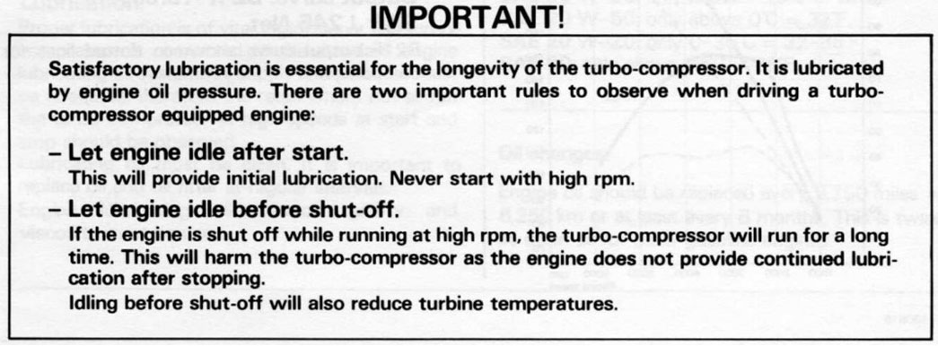 Above image is from Volvo manual TP30309, 1981 240 New Car Features, pg 45. Here are the hose TEES Volvo used for a 240 to upgrade to a water cooled turbo. PN 1378548 is the larger one for the lower radiator hose. PN 1378420 is the smaller TEE placed below the expansion tank.  Is a Water Cooled Turbo Bad for your Cooling System? There are opinions that say a water cooled turbo is a detriment to your cooling system because it sends hot coolant directly back into the engine. This is a valid point. The extra heat in your coolant will make it harder to cool your engine. So in my humble opinion, here was another opportunity for Volvo to increase the cooling system capacity to compensate for turbo cars (more than just adding an oil cooler). More power always makes more heat, but Volvo didn't give the 240 Turbo anything extra for coolant. They left a cooling system in there made for a basic non-turbo, originally designed for a non-AC car. This under-developed system might not be enough, depending on modifications. This of course also depends on the environment and if air conditioning is also pushing the system. A Discussion of Turbo Coolant Lines. or skip to next section: Booster Pumps. I've seen pretty much zero informative in Volvo service manuals discussing coolant hose or pipe routing for a Volvo water cooled turbo. The 240 Turbo originally came with an oil cooled turbo, but I know upgrades to water cooled turbos were widely done by Volvo dealerships after a plaque of failed turbos. And water cooled turbos later became standard in 740 Turbos. I suspect the 240 information came out in service bulletins, but I have never seen it. With very little information, figuring this out can be confusing for Volvo turbo owners, so I made this diagram below from my own observations. The coolant circulation is passive, so we can hope negative pressure from the lower radiator hose suction effect will help keep circulation moving in the direction needed. Original Coolant Pipe Routing. 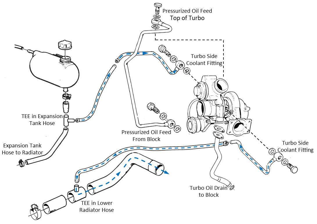 A note of interest: It really doesn't matter which fitting on the turbo goes IN from the expansion tank hose and which goes OUT to the lower radiator hose. Coolant can flow either direction through a turbo. As already mentioned, there are NEGATIVE aspects to having water cooling hoses on a turbo. It's good for the turbo, but not as good for the engine. The good part is the turbo should always get cooler coolant from the cold side of the radiator, but allowing hot coolant from the turbo to enter the water pump and go back through the engine is less of a good idea. How bad? Who knows? If your cooling system is large enough to handle the extra load or if you're somehow otherwise confident your engine won't suffer from this hot coolant injection, then maybe all will be OK. If you're not so sure, it is possible to improve this. See the next diagram below. Bringing an Electric Booster Pump into the discussion. or skip to next section: Intro to the Electric Booster Pump. If you do any online research into Volvos using Electric Water Pumps or Booster Pumps in places like TB, you'll find some, but not as much as you might hope, considering the decades of performance discussions. One reason for this is NOT because questions haven't been asked. They have. From my observations, far too often when someone would ask, a high number of the responses were from short-sided people (I'm trying to use polite words) who didn't actually know sh*t; "That's for drag racing only," or, "That's not reliable and there's NO reason ever to not use the factory pump." Maybe those people should do more research before spouting off. The hostility often resulted it the discussion being shut down. Maybe you can GUESS why I almost always choose to post my research in my own pages instead of in discussion threads. Please keep in mind that BMW has been using Electric Water Pumps and Electric Booster Pumps since 2006. Mercedes almost as long. Lot's of other cars have them too and they have sound uses. In this section I'm proposing adding a small Electric Booster Pump (EBP) near the expansion tank with the purpose of creating positive coolant flow through the turbo and out to circulation. I think it might be more difficult to get satisfactory flow as shown below without a small pump to boost flow. This is because I've proposed the final exit of coolant from the turbo to go to a TEE in the TOP RADIATOR HOSE. Because that seems like a proper place for hot coolant to go. I suspect that there might be enough pressure in the top radiator hose to slow down or interfere with the incoming coolant from the turbo hose, unless a pump is helping push it along. Going further, this offers a nice opportunity to add a temperature sensor in a location that would allow a pump controller to regulate pump speed or frequency. And it would certainly be a nice benefit if such a controller ALSO allows the pump to continue running for a few minutes AFTER ENGINE SHUTDOWN. Would that make things better? Yes, I think it would. If you prefer, this can be considered experimental until someone shows it being done. I have not actually done this, but I'm convinced it would make your turbo happier and your engine would get ONLY nice, cool coolant from the cold side of the radiator. Modified Pipe Routing with Booster Pump. 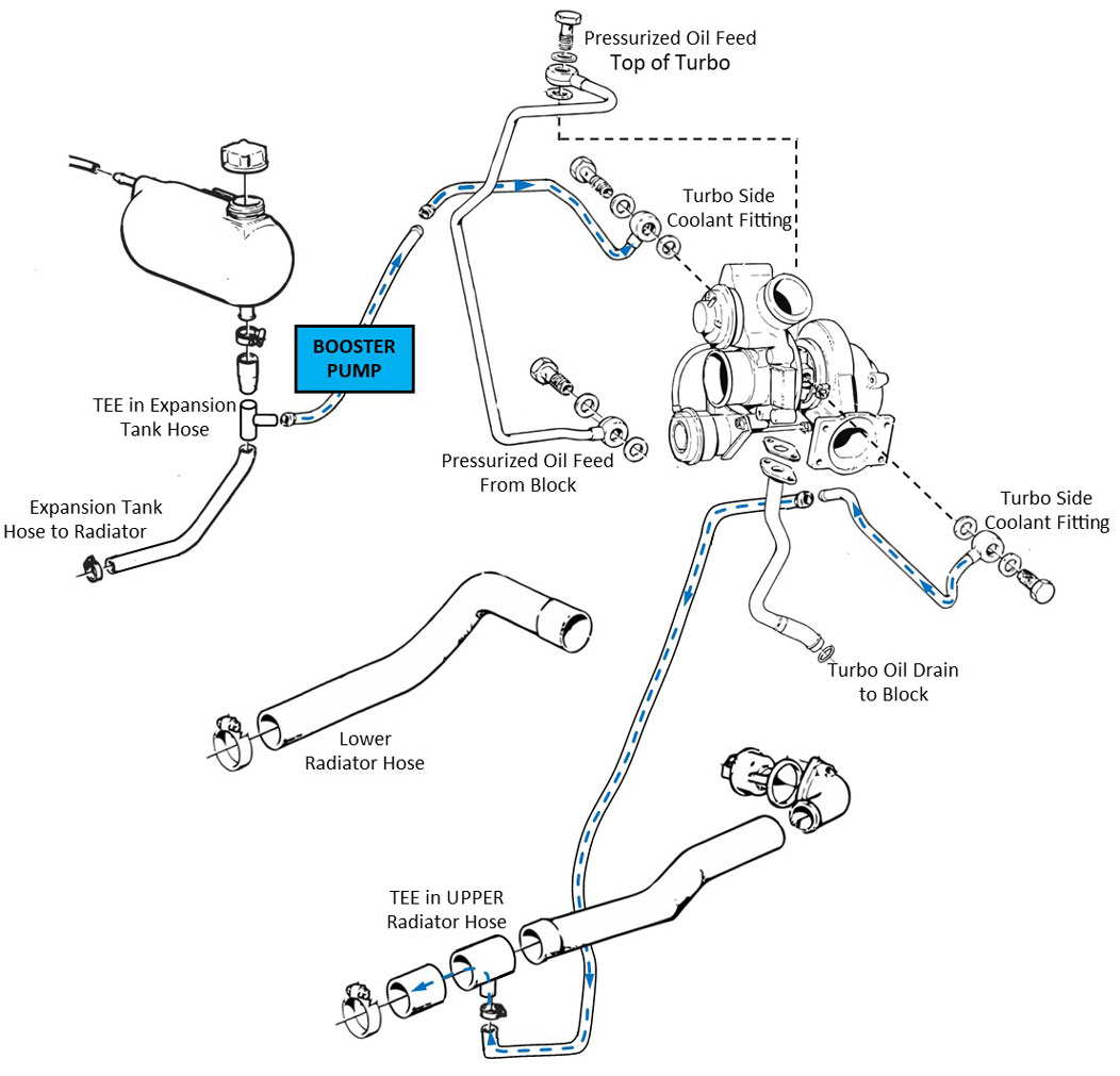 Intro to the Electric Booster Pump. or skip to next section: Electric Booster Pump in a Volvo. Here I'll show you some info I've gathered on small Electric Booster Pumps (EBP). EBPs are sometimes also referred to as electric water pumps. Sometimes they can be the same thing, but for this discussion I'll insert a distinction. For this information, a 12 volt DC booster pump will be considered something that's smaller and more compact that a typical electric water pump (EWP). The fluid demand and capabilities will also be quite different. Sometimes you'll come across intercooler booster pumps for water to air intercoolers. These can usually be considered the same as an EWP or an EBP and they can also widely vary in flow capabilities. Example size comparison: BOOSTER versus WATER PUMP.  Larger electric water pumps are often rated for flow output in liters per minute (l/min), but sometimes also in liters per hour, gallons per minute, etc. A dedicated EWP installed to replace an existing mechanical water pump might have a flow in the range of 100 to 160 liters per minute. A small booster pump might be rated for only 1000 liters per hour (l/hr). This would equal 16 l/min, quite a bit less compared to 100 l/min. So a small BOOSTER would not be appropriate to keep your whole engine cool, but it certainly can be used to circulate coolant in turbo hoses. A larger EWP would be overkill for a small booster job. Most EWPs will have IN and OUT ports that are around 32 to 51 mm diameter (1.25 to 2 inches). A small booster pump might have IN and OUT ports that are only 19 to 22 mm (3/4 to 7/8 inch). A booster pump usually needs to fit in a smaller space, so we should talk about size and weight. Many average sized EWPs can weigh 2 or 3 lbs. Often a larger brushless EWP (below) can be heavier, sometimes 4 to 5 lbs. Many booster pumps can weigh between 0.7 lb. to 1.3 lb. For these example images below, I've included some pumps from Davies Craig to show size comparisons. Davies Craig is not the only source for these things, but they can be a pretty good place to start looking and use for comparison. Below a Davies Craig EBP23 booster is shown next to an EWP150 water pump. 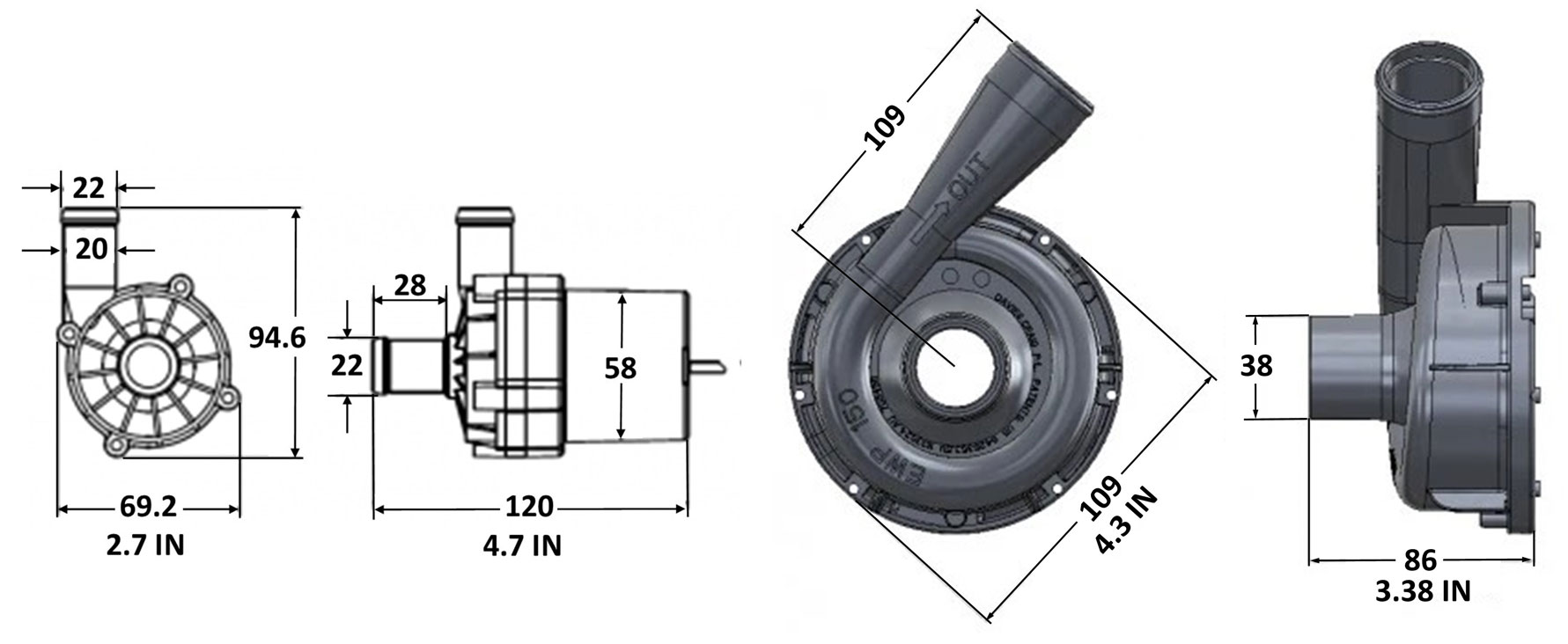 And below we have a larger Davies Craig EWP180 Brushless Water Pump. 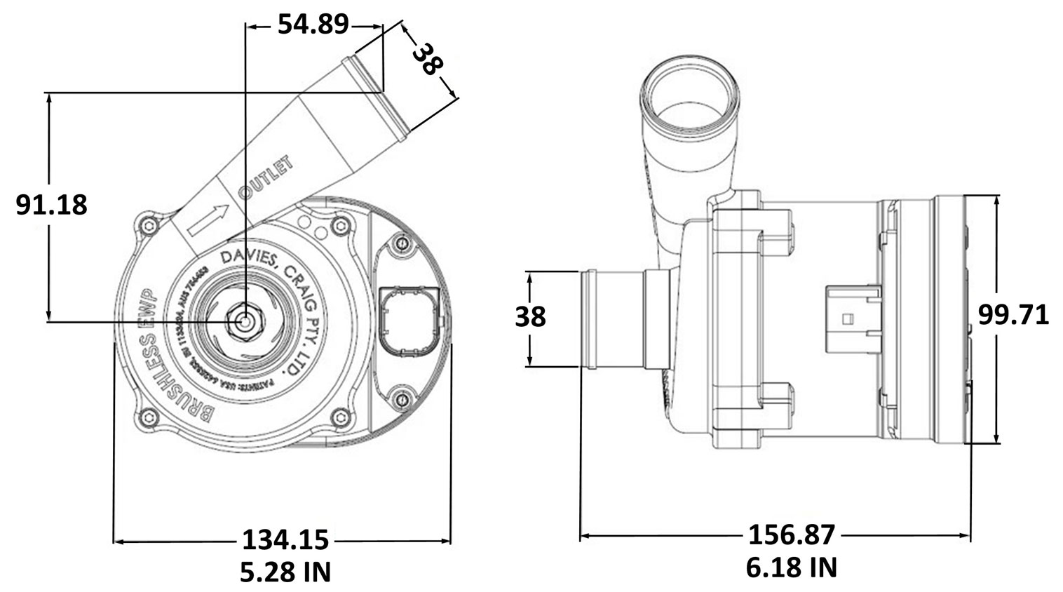 Has an Electric Booster Pump been used in an older Volvo? or skip to next section: Variable Speed Brushless Booster Pumps. Yes. I'm aware of one. It was not used for cooling a TURBO though. In 2012 Nathan (TB user nathaninwa) shared in the below discussion threads a very small bit of info on the addition of an electric water pump and an electric booster pump for his B230 16 valve turbo engine. The booster pump info from his thread will be shared here. The EWP info will be shared later. https://turbobricks.com/index.php?threads/941g-16v-turbo-build.199503 https://turbobricks.com/index.php?threads/electric-water-pump-on-b230.272309/ Nathan used this booster pump to boost the coolant flow coming out of the back of the cylinder head, through the heater core, and then back to a port mounted in a custom freeze plug in the block. Sorry, that's all he provided and he doesn't answer PMs. The reason the coolant in this example did not return to the water pump pipe and to the back of the mechanical water pump as it would normally was because his mechanical water pump had been eliminated.  It took some searching, but I identified this booster pump. It's a Bosch PN 204-835-03-64 auxiliary pump used in a number of Mercedes Benz cars from 2008 to 2025. Another part number is Bosch 2115060000. The only on-line listing from Bosch I've found is here. Not much info other than photos.: https://www.boschautoparts.com/p/water-pumps-0392023004- Here's what I've managed to find. This 12 volt Bosch pump has a brushless motor (with a 2-pin wire connector). It weighs about 0.7 lbs. It draws 0.7 Amps. Operating Pressure (PSI) 1.45. Flow: 4 GPM (15L/Minute). The mating 2-wire connector you will need will be TE 967412: https://www.te.com/en/product-1-967412-2.html 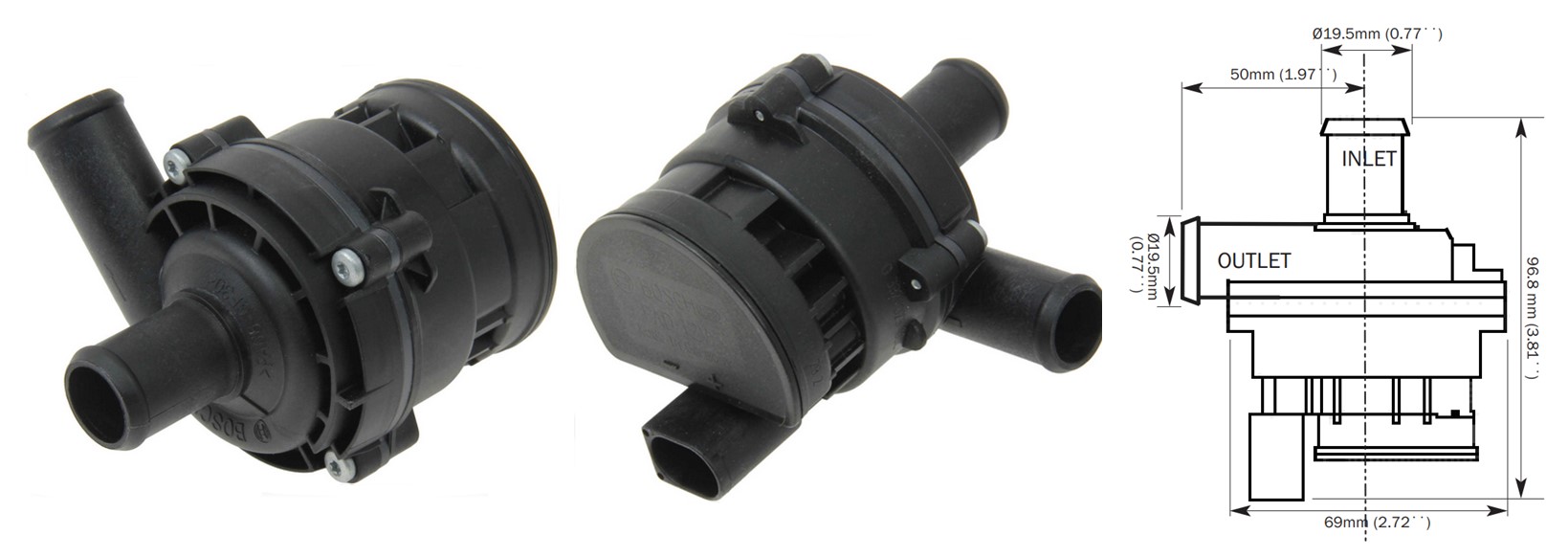 This spec sheet suggests this pump was available from Davies Craig at one time. https://dalhems.com/f/d/eb99b31725204494a06e9b9200f9beb9/EBP_Installation_Instructions.pdf And in the Davies Craig 2016 catalog it was listed as EBP15. https://outlawspeed.com.au/shop/media/wysiwyg/files/brand_catalogues/DaviesCraig_EWP_2016_Catalogue.pdf It's still available and can be been found at a number of places. https://www.fcpeuro.com/products/mercedes-engine-auxiliary-water-pump-2118350264-2118350265 https://www.germanautoparts.com/bosch/auxiliary-water-pump/204-835-03-64 So a booster pump like the above Bosch might be an option. Your decision will also depend on how it'll be controlled. Just wiring a pump to run all the time is not the way. It should have some sort of device to control it, based on when it should come on and for how long. One option is a DC Relay Controller as shown below. Since this pump has a 2-wire connector, it should be clear (even though it has a brushless motor), that this pump can only be run ON or OFF. A brushless motor with two wires is activated the same way as a normal brushed DC motor using a relay or relay based controller. It does not run as a variable speed pump the way a more modern PWM controlled brushless pump might be able to. That doesn't make this pump a bad choice. This pump draws very, very little current (not like a big cooling pump can). If a controller is set up to turn this pump on/off at intervals using a coolant temperature sensor, you'll probably never notice it running. If you need a suggestion for a temperature based 12v DC relay controller that can run a pump like this, this one can do the job very inexpensively. It comes from the same place (https://gkgoodcheapparts.com) as the PWM brushless fan controller I installed for my 240 to run my 18 inch brushless fan (details of that in my Brushless Fan Page HERE). https://gkgoodcheapparts.com/products/widget-man-fdm2-self-learning-dc-fan-relay-controller   After Run Timer-Controller. New for 2026 (with more info coming later), the Widget Man FPMR is purpose-designed to work with Widget Man fan or pump controllers, or it can work with many other controllers or it can drive relays. This controller output has an 11.5V precision voltage regulator with 1 amp capacity, enough current to power multiple FPM's, multiple relays, or any mix your setup may require. The timer can run from 0~5 minutes, and there's an optional temperature input which can prevent after-run when it isn't necessary. The temperature sensor can be separate or shared with an FPM or FDM2, depending on your needs. For instance, this device can easily respond to intercooler temperature while the FPM / FDM2 responds to coolant temp. The FPMR “learns and remembers” your chosen cutoff temperature the same way as the FPM / FDM2, so adding temperature to the timer is as simple as 2 button presses. The FPMR can also run with no timer and only temperature if desired, giving you total latitude in meeting the needs of your setup. If a true variable speed pump using PWM signals for speed control is more like something you need, I'll cover that next. Variable Speed Brushless Booster Pumps. or skip to next section: Electric Water Pumps. Controlled using Pulse Width Modulation (PWM). There are a number of choices out there. Sometimes models come and go. I'm going to highlight a couple to help explain. This EBP is Bosch PN 039202453G. It's a brushless pump with a 3-pole connector. The S-pin in the connector controls the pump speed using a PWM signal, pretty much exactly the same way as a brushless cooling fan. The advantage of a pump controlled this way is that it can be commanded to begin at a low speed or a fast speed, ON or OFF, etc., based on your custom programming and using a simple coolant temp sender (even a universal sensor) to maintain a certain coolant temperature, as long as the sender is resistance-based like most of them. For control, a stand-alone controller would be possible or it can be connected to a programmable engine management system if that's what you have. This pump is slightly larger than the first one above. About 4.6 x 3.2 inches and it weighs about 1 lb.. It's rated at 1000 liters per hour. 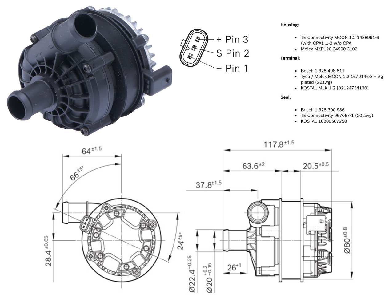 Bosch has a page for this: https://www.bosch-ibusiness.com/products/product-categories/auxiliary-pumps-and-valves/pce-039202453g/ Or they have a page listing several others: https://www.bosch-ibusiness.com/products/product-categories/auxiliary-pumps-and-valves/ If you're looking for pumps like this, you can search for Bosch electric cooling pumps (and be sure to choose 12 volts, because some are 24v). Or search non-Bosch and see what's out there. Sometimes these are listed as booster pumps or auxiliary pumps. This EBP is Bosch PN 039202343G. It's also brushless with a 3-pole connector. This one is smaller and lighter. About 3.5 x 3.5 inches and it weighs about 0.7 lb. It's rated at 500 liters per hour. 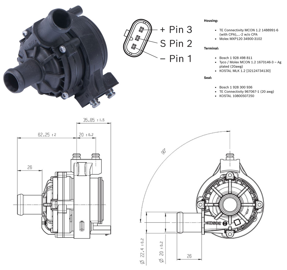 Bosch has a page for this at: https://www.bosch-ibusiness.com/products/product-categories/auxiliary-pumps-and-valves/pad2-039202343g/ This controller below is what I used for my brushless cooling fan conversion. It's very compact. This would also be appropriate for a brushless booster pump or brushless EWP. Details about this controller, installation, programming, etc can be found HERE.  This Universal PWM Brushless Fan or Pump Controller can be found at: https://gkgoodcheapparts.com/products/fpm-brushless-fan-control Direct link for PDF instructions: https://drive.google.com/file/d/pli=1 NEXT: Electric Water Pumps (EWPs) Some info on EWPs has already been shown above. Some will also repeat here. A couple links below can also give you some background on what has been done or considered in the past in Volvos https://turbobricks.com/index.php?threads/b21-b23-b230-electric-water-pumps.18152/ https://turbobricks.com/index.php?threads/searching-electric-water-pumps-on-b230s.239602/ I discussed Nathan's (nathaninwa) booster pump installation above in the booster section. Below I'll add some more info about the EWP Nathan used. His installation is NOT a typical EWP setup. It's more advanced, but it can help with your understanding. Here are a couple links with nathaninwa content that may help. https://turbobricks.com/index.php?threads/941g-16v-turbo-build.199503 https://turbobricks.com/index.php?threads/electric-water-pump-on-b230.272309/ The pump below, used by Nathan, is from Davies Craig daviescraig.com. The model number he used was not shared. This is a brushed motor type. Here's a 40 page PDF catalog from Davies Craig. The catalog offers useful information on matching a pump to engine displacement and comparing output, amp load and other stuff. Keep in mind they offer 12 volt and 24 volt models. https://daviescraig.com.au/media/2576/1688618225.CatalogueV8Small6-July-2023.pdf 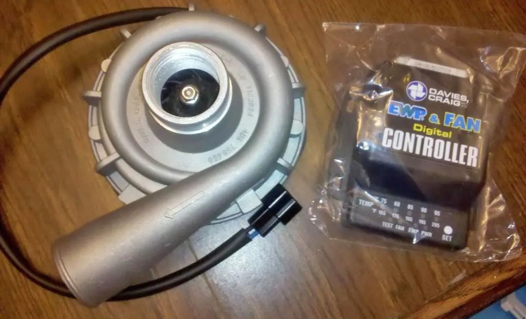 Davies Craig Electric Water Pump Pages: https://daviescraig.com/ The CONTROLLER shown ABOVE is specific to a brushed motor pump. A brushed motor is controlled by a relay, which will switch it ON or OFF. The Davies Craig controller above is no different, however, it's capable of sensing coolant temperature and it can vary the ON/OFF frequency of the pump. For example, the controller can set the pump to run ON for 10 seconds and OFF for 30 seconds to maintain a temperature. And it can continuously adjust that frequency to keep a steady temp. This method is similar to how a brushed cooling fan is controlled ON or OFF as needed in an older Volvo. A negative aspect to running a DC motor with an ON/OFF setting is the heavy load on an alternator, but since most of these pumps only consume 7 to 10 amps, the load will be small. Davies Craig EWP 150 (brushed) pump shown below. Up to 160 l/min. Maximum load: 10 amps. Weight: 2.6 lbs. 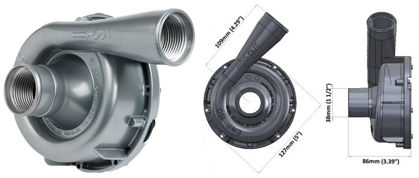 BRUSHLESS PUMPS. More modern pumps are available with BRUSHLESS motors. These can be controlled to run at variable speeds, instead of ON/OFF. So a brushless pump can run slower if needed and will speed up or slow down to maintain the temperature. Davies Craig offers some brushless pump models and controllers HERE: https://daviescraig.com.au/category/brushless-electric-water-pumps. Davies Craig EWP 180 (brushless) pump shown below. Up to 180 l/min. Maximum load: 33 amps. Weight: 4.4 lbs. https://daviescraig.com.au/product/brushless-ewp180-kit-remote-electric-water-pump-12v8450 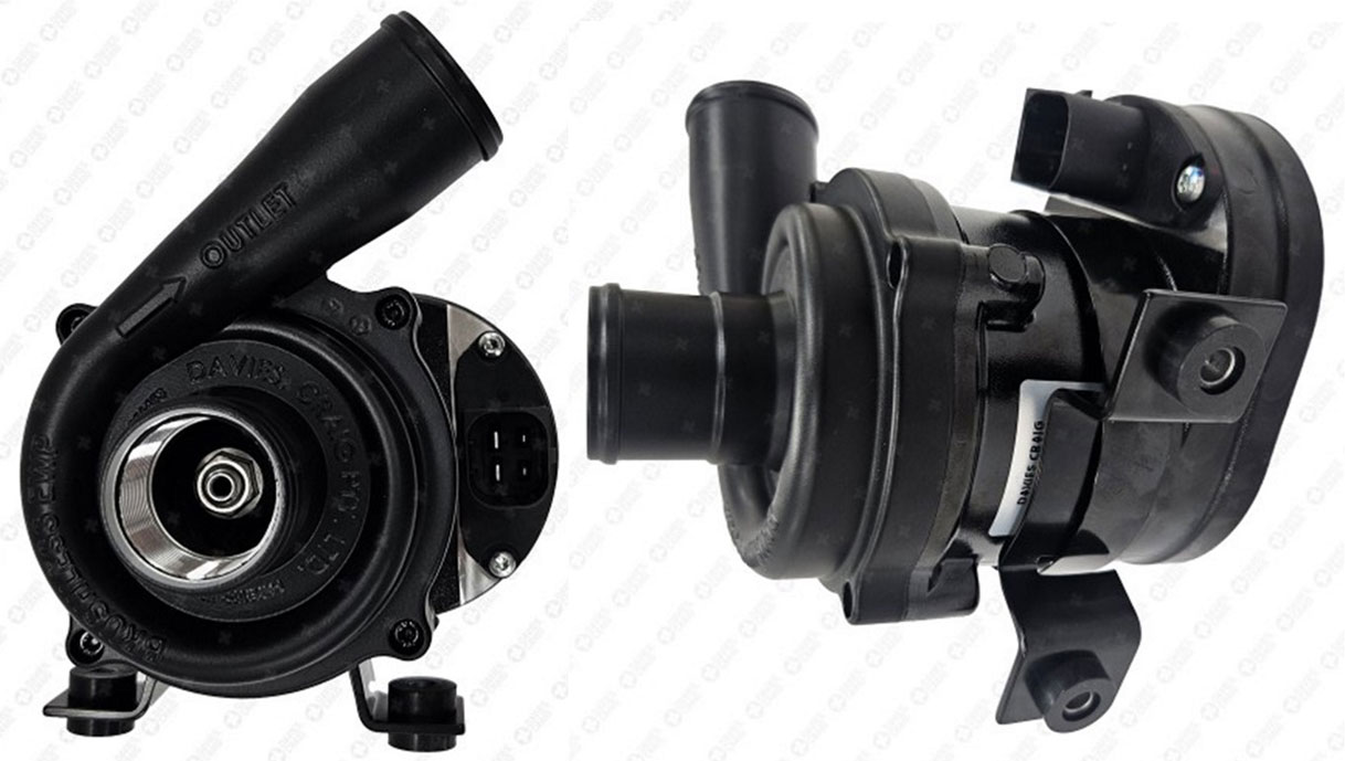 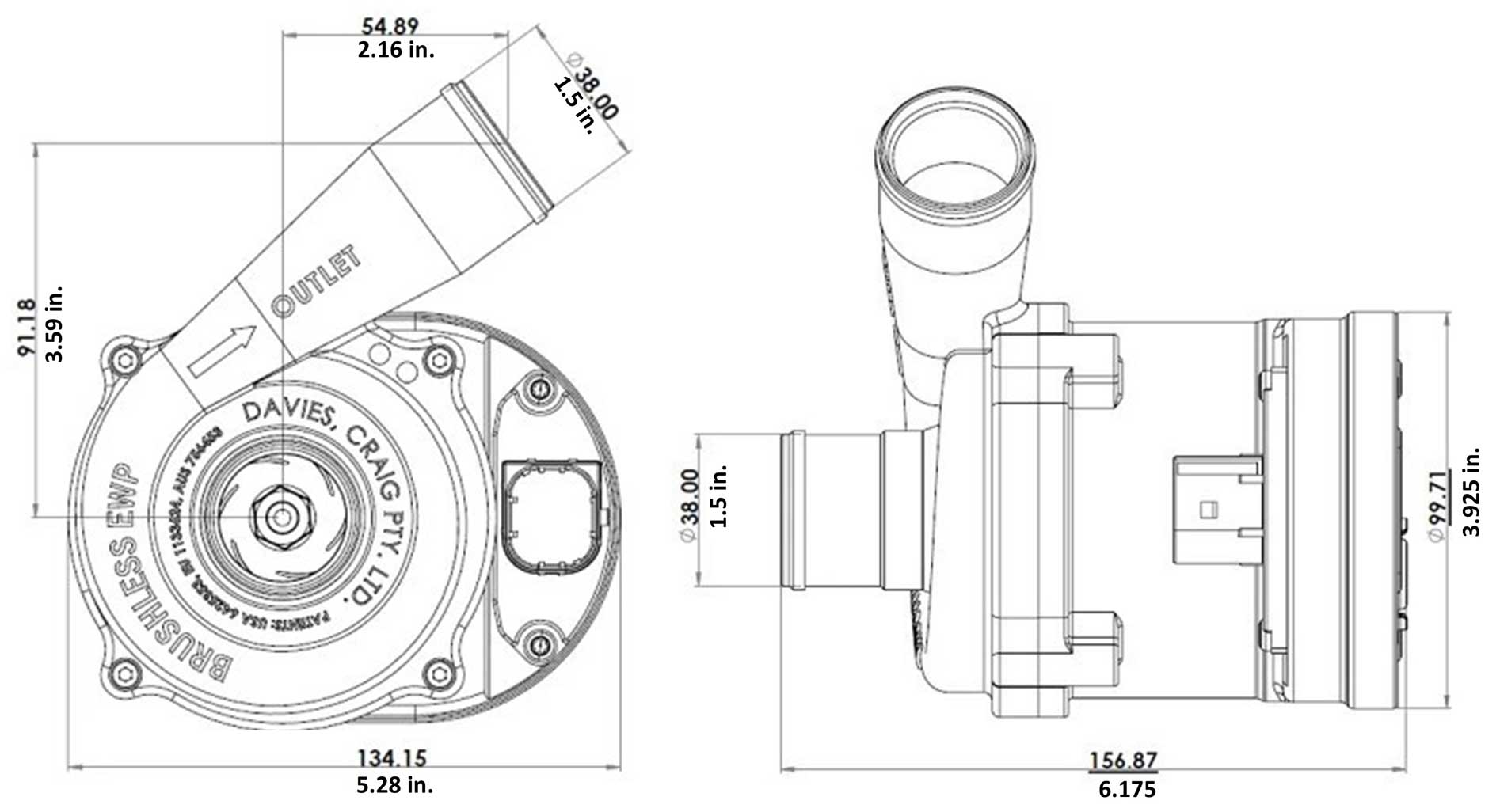 Where to mount an EWP. By far the most common mounting location for an EWP is in-line with the lower radiator hose. For lighter weight pumps, the hose will be enough to support it. Or a mount can be used to support a heavier (brushless) pump.  Nathan opted to mount his pump to the frame on the exhaust side of the engine. 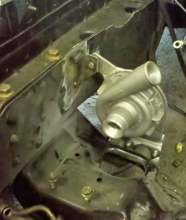 Here's the hole in front of the block where coolant enters. There's also a second smaller hole up and to the right. I think that may be an air bleed for the pump impeller chamber. Something needs to be used to feed coolant from the pump to this entrance. 
Nathan chose to create a custom cover with a port. 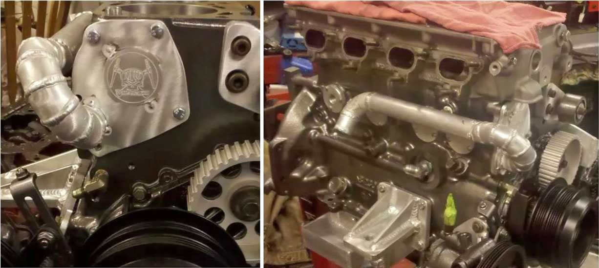 Others have chosen to modify a stock water pump housing to create a manifold. The examples below show an eliminated a belt pulley. If you still need a belt pulley in this location, it would not be difficult to add an idler pulley to this. https://turbobricks.com/index.php?threads/electric-water-pump-on-a-b230-am-i-nuts.171835/ 
https://turbobricks.com/index.php?threads/kill-build-vol-2.371755/ 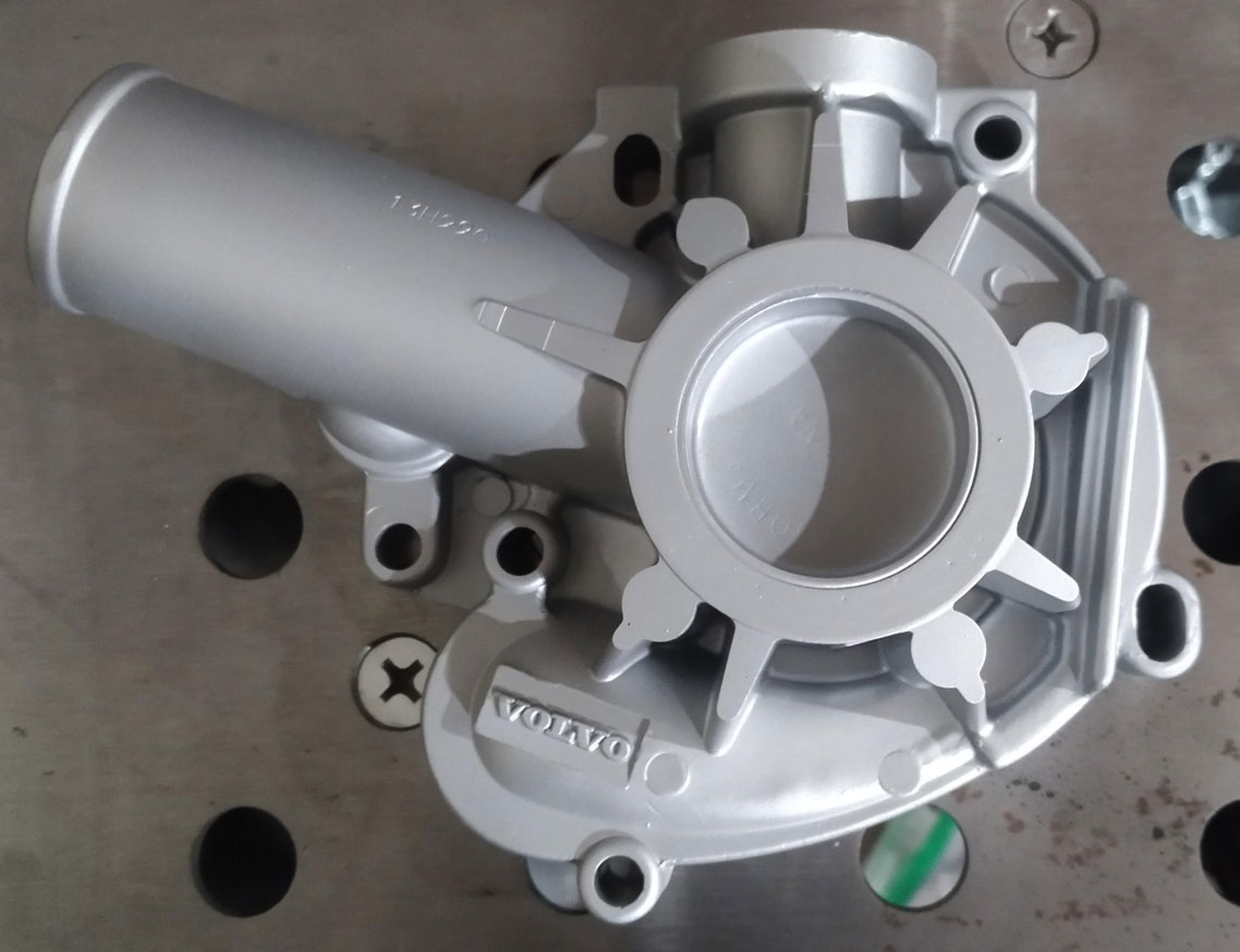 |
|||||||||||||||||||||||||||||||||||||||||||||||||||||||||||||||||||||||||||||||||||||
| ly |
|||||||||||||||||||||||||||||||||||||||||||||||||||||||||||||||||||||||||||||||||||||
|
|
||||
| davebarton.com |
prancingmoose.com |
240turbo.com |
Special Emblems |
|
| Prancing
Moose Stickers |
Volvo
Stickers |
Body/Chassis/Engine
Labels |
240 MODS and FIXES Page | |
| Other Car Brand
Stickers |
Steering
Wheel Labels |
Center Cap Labels/Overlays |
Cool Volvo
Products |
|
| Grill Labels/Overlays |
Volvo Wire
Harnesses |
Conversion Harnesses |
Harness
Parts/Connectors |
|
| Volvo Relays |
Coil Repair
Harnesses |
240 Window
Scrapers |
740/940
Window Scrapers |
|
| Adjustable Voltage
Regulators |
Horn Buttons |
240 Odometer
Repair |
740 Odometer
Repair |
|
| Volvo Gauge
Faces |
740
Turbo/Boost Faces |
240 Black Door Vinyl |
850 Odometer
Repair |
|
| ALTERNATOR Page |
240 Power Mirrors - Switches |
240 Oil Cooler Page |
240 Fuse Panel Page |
|
| Group A
Racing 242 Turbo Page |
240 Hydraulic Clutch | Fuel Pump RELAY Page |
240 Headlight RELAY Page |
|
| Used Parts & Extra Stuff for sale |
CRIMPING Page |
240 Ignition Page |
240 Headlight Page |
|
| 240 Gauge Electrical Diagrams | 240 REAR END Page | Yoshifab Catch Can Install | 240 TAILLIGHT Page | |
| Side Marker
Lights Page |
Gentex Mirror Upgrade | Yoshifab Drain Tube Install | Modified 240 Favorites | |
| SoCal Salvage Yards | Unleaded Racing Fuel | B26FT Stroker | Dave's 245 Spec Page | |
| 240 SUSPENSION Page | 240 Lowering Page |
240 Windshield Page |
240 WIPER Page | |
| 240 BRAKES Page |
240 Dash Top Gauge Pod | Cadillac 4-Note Horn Install | 240 DYNAMAT Installation | |
| 4 Speed Fan
Controller |
Electric Cooling Fan
Page |
BRUSHLESS Cooling Fan Page |
Tropical Fan
Clutches |
|
| 240 AC Page | "KOMFORT BLINKER" Upgrade | T5 Trans Conversion Page | 240 Engine Mount Page | |
| 240 VIN Page | Stepper Idle Valve Page |
Vacuum Diagrams | 240 HOOD Page | |
| 240 Exhaust Page | 242 Power Vent Window Project |
EFI Volvo Pin Function Diagrams |
Favorite Links | |
| R-Sport
Apparel |
Prancing
Moose Apparel |
Volvo Meet Photo Albums | Texas Volvo Meets and Events | |
| Ordering Instructions | Policies | PAYMENTS Page |
Mojave Road Trail Map Page |
|
| Returns | Shipping | Shopping Cart Troubleshooting | Contact Us |
|

|


 alternators are known for poor voltage.")


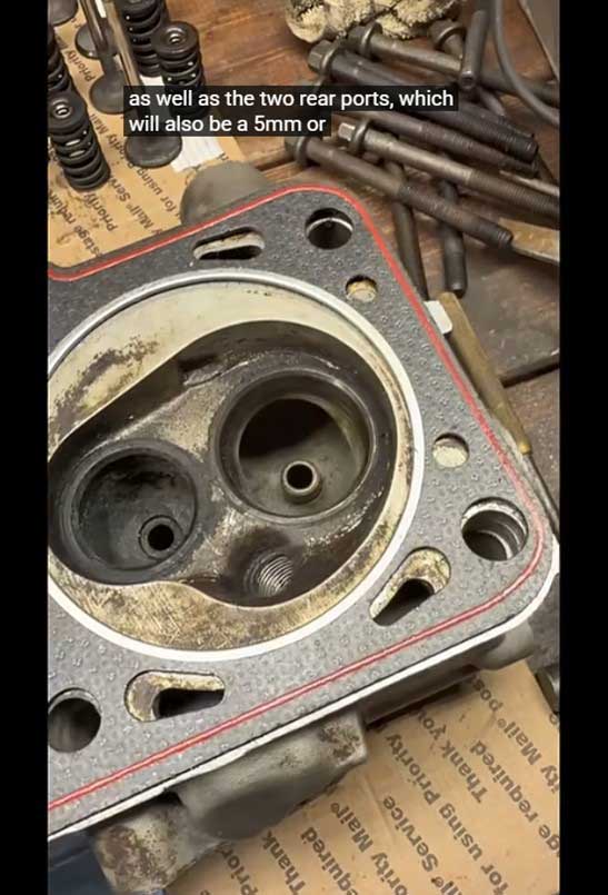
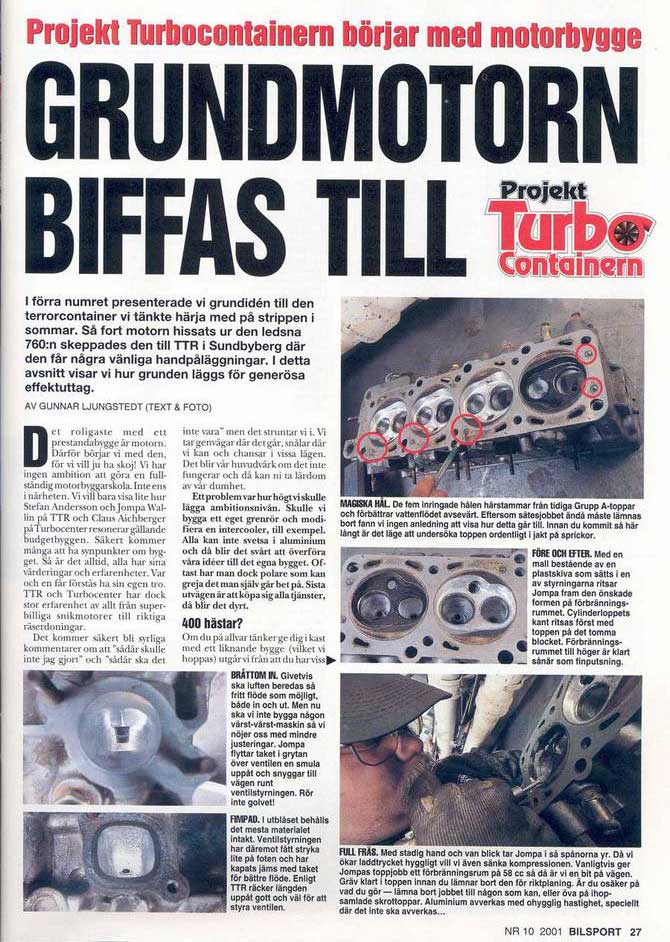