| Cadillac 4-Note Horns for my Volvo 240 |
 |
UPDATED: January 14, 2024
CONTACT

|
D O
M A I N S   |
|||
 |
 |
 |
 |
 |
 |
 |
 |
 |
 |
 |

|

|
|
 |
 |
 |

|
|
 |
 |
 |

|
 |
 |
 |
 |
 |
 alternators are known for poor voltage.") |
 |
 |
 |
 |
 |
 |
 |
 |
 |
 |

|
 |
 |
 |
 |
 |
Send me an email if you do something like this to YOUR Volvo.
CONTACT
|
||
|
This is what stock 1984 Volvo 240 horns look like.
 They're mounted behind the grill. The original horns sounded ok. Nothing special. I wanted something SPECIAL!. 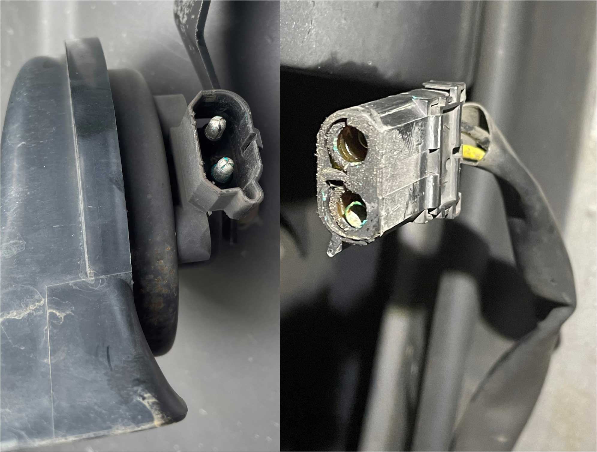 Here are what a later 240 horn looks like below. They have a newer style connector that's somewhat sealed. This one above is from 1993. Note the YELLOW and BLACK wires. All 240s seem to have those same wire colors. If you don't already know, 240 horns are wired backwards compared to most normal cars. The YELLOW wire supplies direct 12v power (whenever the key is ON). It does not activate the horns. The BLACK (ground) wire activates the horns. It's wired through the horn switch in your steering wheel and when that switch closes, the BLACK wire provides the GROUND to make the horns blast. |
||
| I had been thinking about doing a LOUD HORN
upgrade for a while and I finally pulled the
trigger. I found a set of these four (4-note) Cadillac horns
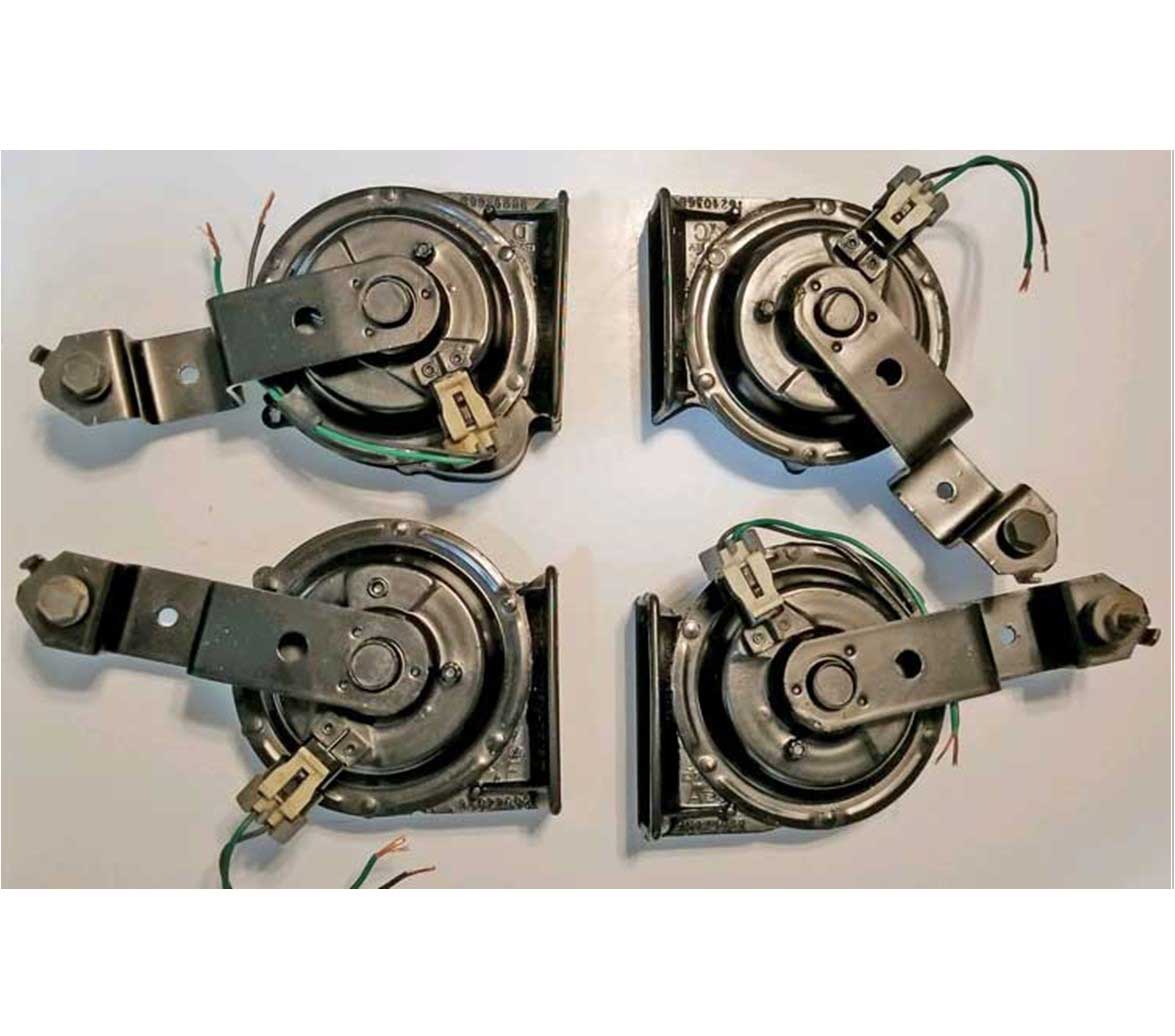
online and bought them. These are known as Cadillac 4-Note Horns. I don't know the specific years, but these horns were apparently equipped in many Cadillacs up into the 1990s. Specifically they appear to be found in Cadillac DeVilles until about 1985 (after which the DeVille was downsized). They also came in Cadillac Fleetwoods and some large Buicks until about 1995. Also supposedly in Oldsmobile Toronados until about 1985. These horns below are made of steel and plastic. Much earlier Cadillacs and large GMs got 4-note horns going back into the 1950s. Those much earlier horns were all metal and may have very different markings than I have pictured below. The four horns below are each tuned to a separate musical note: A, C, D and F. Later cars with only 2 horns reportedly got only notes A and F. After the 4-note horns were discontinued, all GM cars came equipped with only two horns. |
||
 |
||
|
||
| The round portion of these horns is stamped steel and the trumpet section is molded plastic. Each horn has the note A, C, D or F embossed as shown here. 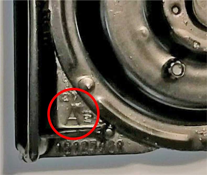
|
||
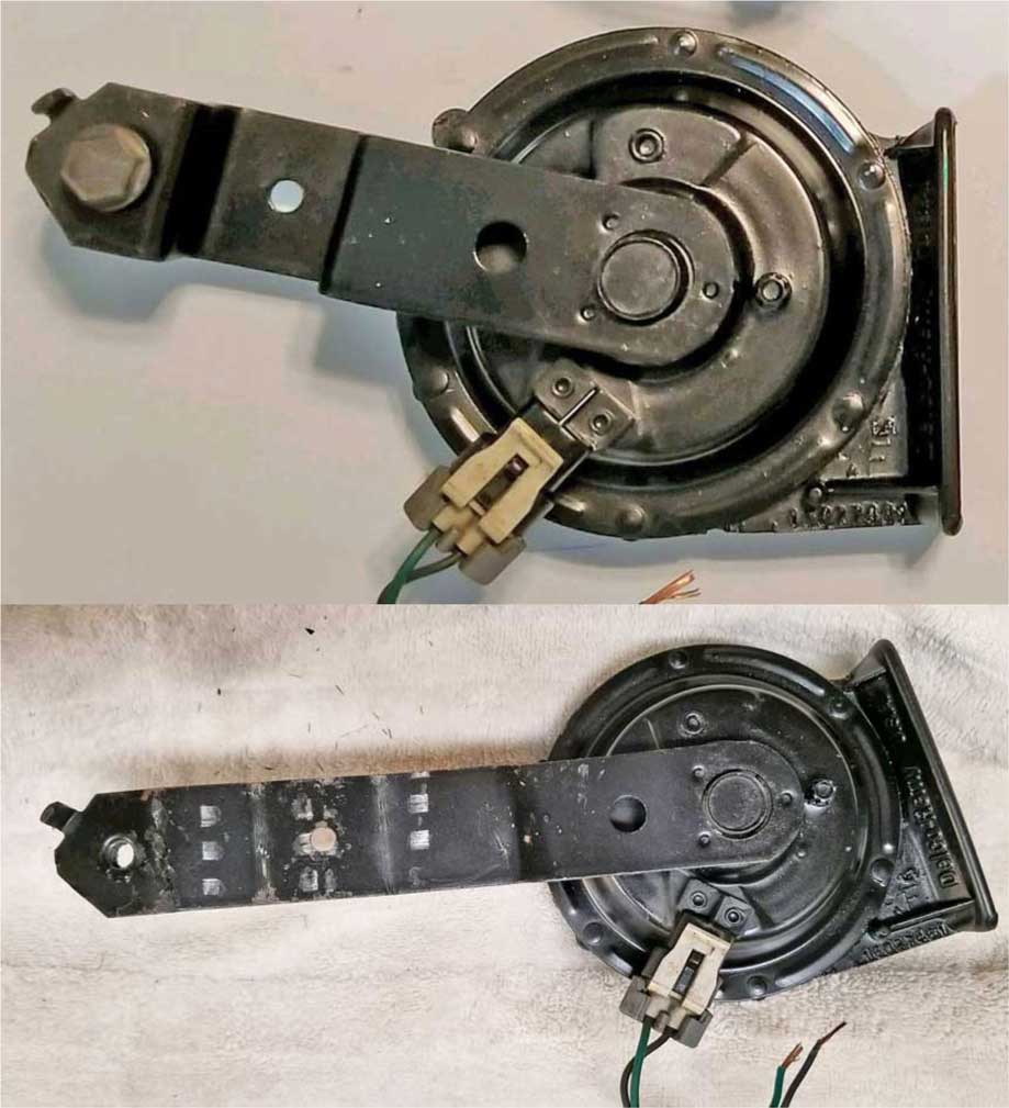
| The horns I used have two-wire connectors (power and ground). These are reportedly later model 4-note horns. When shopping for horns, be aware that there are some (see lower photo) which have only ONE wire to each horn. That wire is the power wire. These are reportedly earlier horns. On the ONE-wire horns the ground circuit is completed through the mounting bracket. I don't think this makes any difference in how they sound. Just be aware of it in case you have a preference. 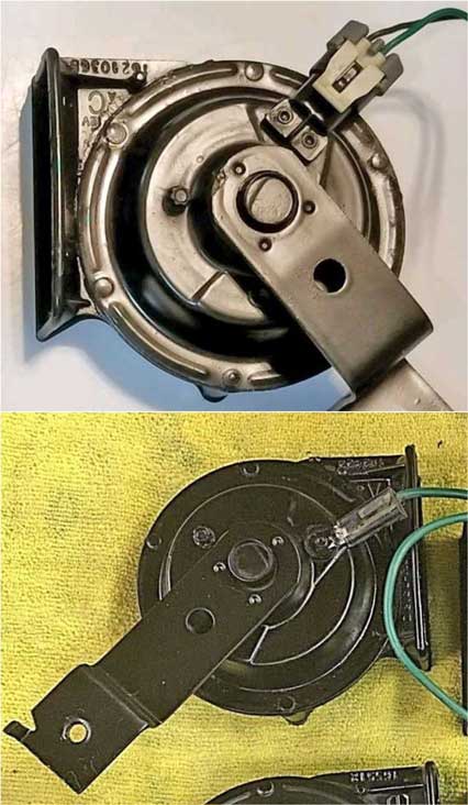
|
||
| VOLVO WIRING If you're installing these in a Volvo 240, you should know these cars don't have normal horn activation circuits. The 240 has YELLOW and BLACK wires as shown here. The yellow wire is the power wire and it has 12 volts whenever the key is in the ON #1 or ON #2 position. The horn is then activated through the black GROUND wire, which is triggered by the horn button on the steering wheel. 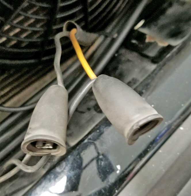
The Volvo 240 does NOT use a relay in the horn circuit. In order to make these 4-note horns work correctly, a relay is recommended and you'll see I added this below. This will allow you to correctly change how the new horns are powered and triggered in a Volvo. If you're installing these horns in a non-Volvo with a normal horn circuit, I would still advise installing a relay to provide power. These horns reportedly draw about 5 amps each and I think they'll always work better when direct full battery voltage is available. |
||
|
WIRING DIAGRAM
Here's a diagram I made. This is how I made my relay circuit. I used TWO relays. Each relay powers two horns. I suspect that ONE relay is probably enough for all four horns, but I did it this way after seeing the majority of other installations on the internet doing it this way. AGAIN, keep in mind that Volvo 240 horn circuits are different from most normal cars. The horn switch on the steering wheel in a 240 is a ground circuit, instead of a 12V power circuit like a normal car. So if you have a 240, look for the two-wire harness going to your horns and you'll find the yellow and black wires shown below. 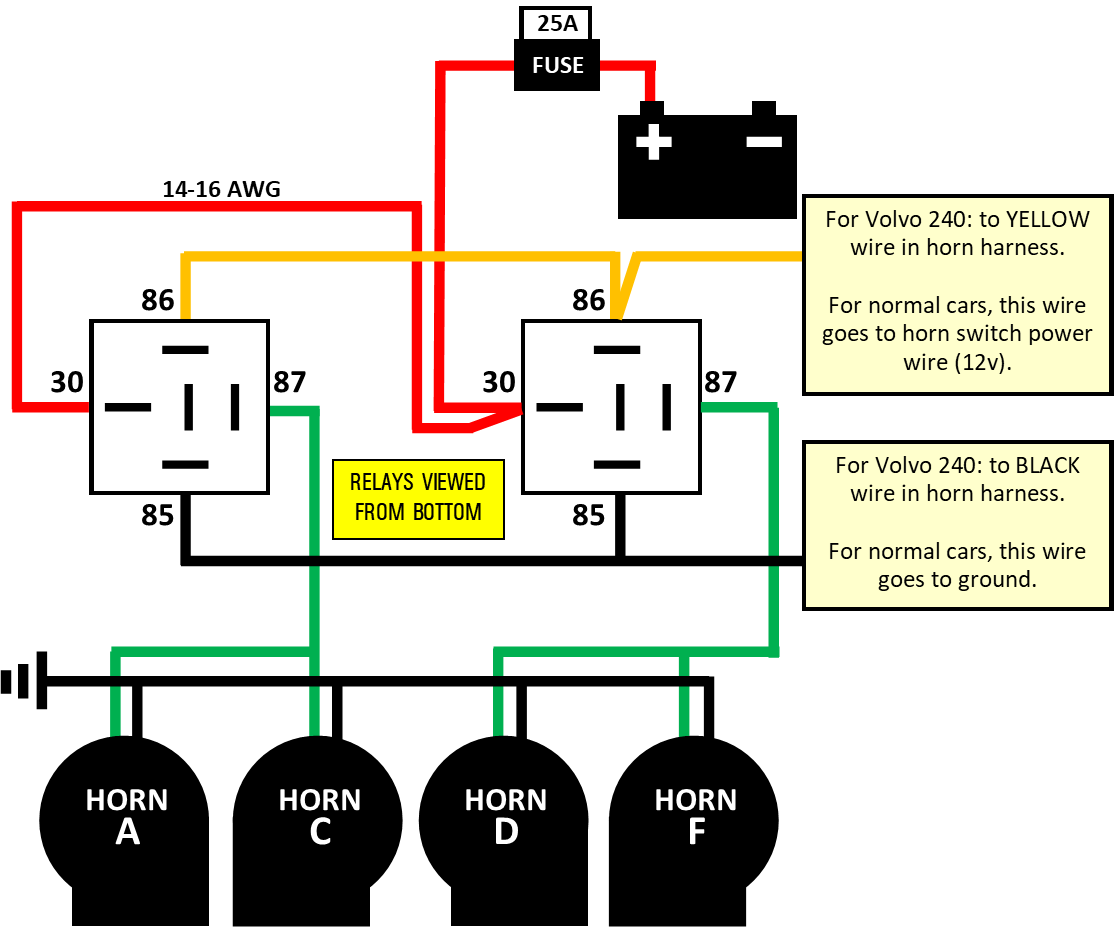 |
||
|
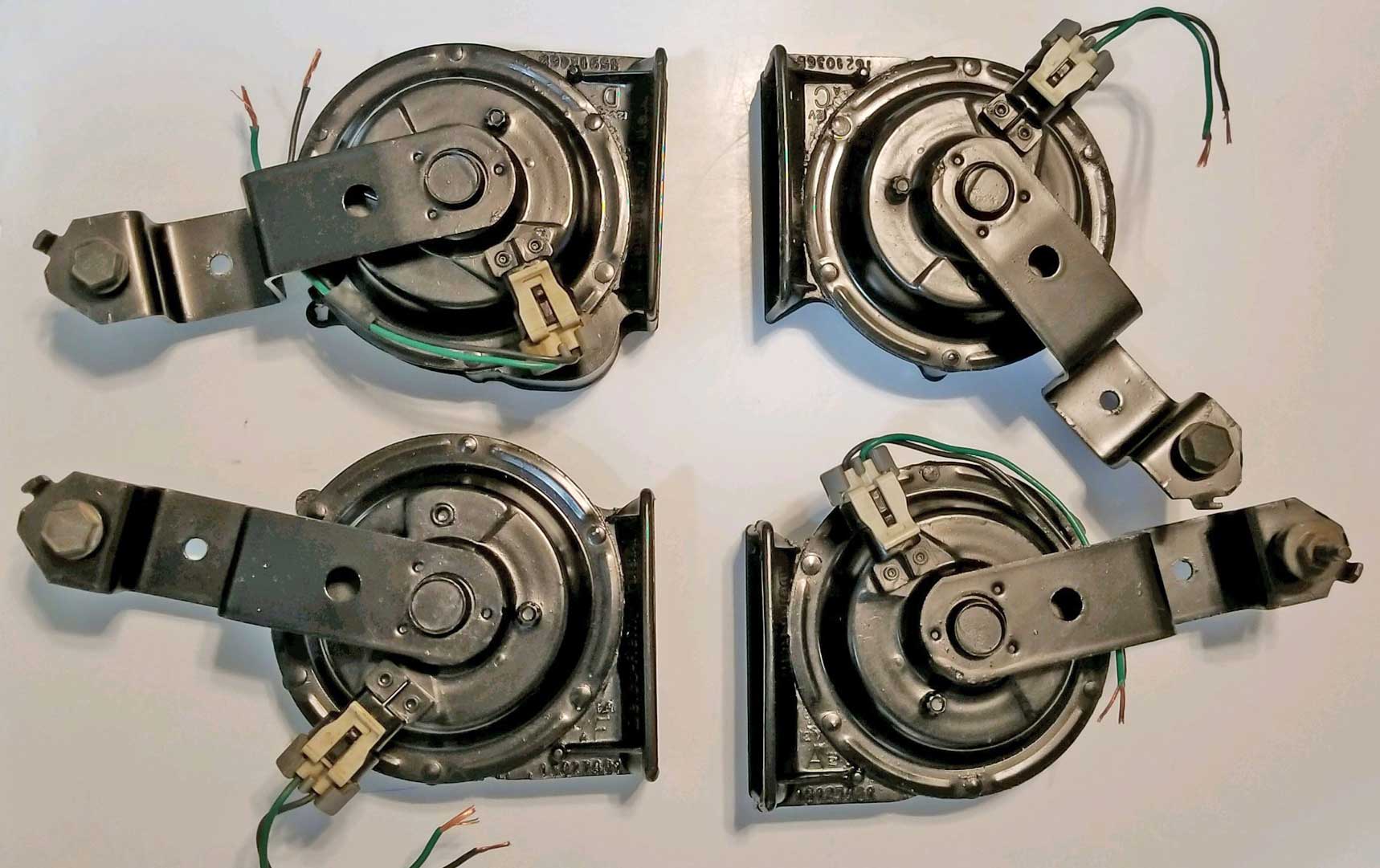
I carefully
straightened the mounting brackets on all four horns
using my bench vise and big pliers. I
also ended up cutting about an inch off the end of each
bracket. That's up to you on if this helps you
mount them.
I've heard it may be possible to mount these so they're too stiff or too rigid. I don't know if that's true, but certainly if you mount them so they can freely vibrate, without touching any solid object will help the sound they pure. Keep this in mind if you're cutting down the brackets. These horns vibrate a lot when sounding, so in my opinion, you should mount them so they are not touching each other or touching any other parts of the car (except of course where the brackets are mounted). When mounting horns, keep in mind that the trumpet openings should always be pointed downward so they don't collect water. Also I have read that the best sound will be from horns that all are mounted close together (all in one spot) and, if possible, all pointing the same general direction. |
||
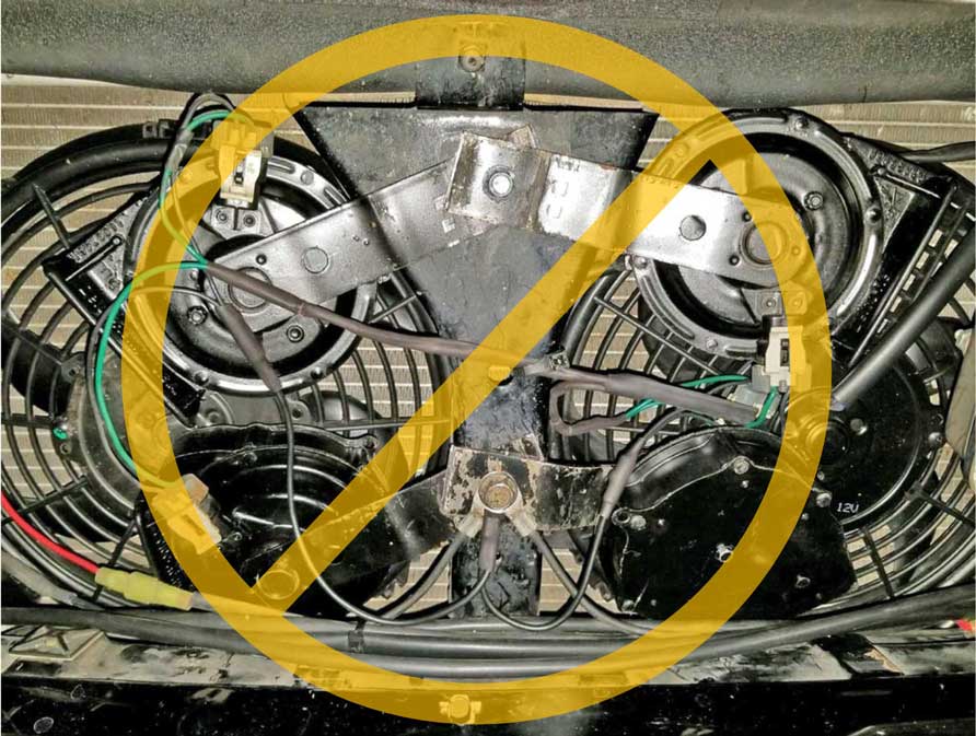 Here's a photo ABOVE of the horns after first being installed
behind the front grill in my 240. After I was done, I
changed my mind because this location had so little room with AC fans there.
I also didn't like how much air these potentially blocked. Plus they were all pointing different directions. So instead I and mounted them BELOW the car. SEE PHOTO BELOW. A 240 has lots of room underneath in the right or left corner, behind the front bumper. I mounted these under the left side, behind the bumper. The horn brackets are bolted to the 240 horizontal support bracket that stabilizes the left fender. It's a TIGHT fit in this space, becuase there's also a charcoal canister. They just barely fit on this side, but they do fit. And none of them are rubbing or touching each other or any other parts of the car. I think that's important because of how much VIBRATION these things generate. You could also consider mounting them on the RIGHT (passenger) side on a 240. More room there. I didn't choose that side because I already had a remote oil filter mounted there. This gives you two great locations to choose from in a 240. I think they're louder in this lower position, since all of the trumpet openings are pointed downward to FREE AIR instead of being pointed at parts of the car. It's hard to tell from this photo, but the lowest part of the horns is well above the bottom of the spoiler and they're not visible unless you get on the ground a peek under the car. |
||
Below photo view is from
the ground looking up.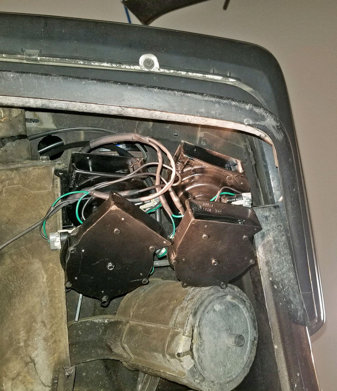 |
||
|
|
||
| MOUNTING DIAGRAM Here's a diagram below I created to illustrate how I mounted these horns. I bent the horn brackets to point the horns a bit forward and to move them away from that charcoal canister. And then I bolted together each pair of brackets above the 240 fender brace so that the brackets sandwiched the brace. I did this because I felt drilling holes in the brace limited my options for small adjustments in the final positioning and my goal was to get these things positioned just right so none of the horns would be rubbing or touching or vibrating against anything.  |
||
If you're wondering what hole I used to bolt these brackets
together in the above diagram, it's this one
circled. 
|
||
| Send me an email if you do something like this
to YOUR Volvo. CONTACT |