| Stepper Idle Valve Control Project GM Style Idle Valve |
 |
UPDATED: January 15, 2023 CONTACT

|
D O
M A I N S   |
|||
 |
 |
 |
 |
 |
 |
|
 |
 |
 |
 |

|

|
|
 |
 |
 |

|
|
 |
 |
 |

|
 |
 |
 |
 |
 |
 alternators are known for poor voltage.") |
 |
 |
 |
 |
 |
 |
 |
 |
 |
 |

|
 |
 |
 |
 |
 |
If you have any comments or if you can improve this information, please feel free to email.
CONTACT
| INTRODUCTION This page details work I did on my idle air control functions for my 242 Turbo. I'm sharing it here for the benefit of others who might be interested in trying something similar. My car uses a programmable fuel injection system from SDS (Simple Digital Systems). I began using SDS more than 20 years ago. Megasquirt is now a popular engine management system, but it didn't exist when I started using SDS, so I have stayed with SDS. And it has been bulletproof and flawless for over 20 years. SDS was originally designed for racing and it does not have, nor can it control a modern idle air control function to control a precise idle system, which more modern EFI systems can do. What SDS offers is the ability to trigger a simple electric air valve to crudely increase the idle for cold warm up or AC idle increase. A simple ON/OFF idle valve can work OK, but it's usually a crude substitute. It generally doesn't work quite as well as you like when temperature changes occur. So the improvement this project made was very successful. It added refinement to my idle functions. For those of you using a GM stepper IAC valve (with a factory GM EMS, aftermarket EMS, Megasquirt, etc.), this extra control function detailed here may be a welcomed addition for you too. First watch Jon Lamb's video below. He shows how he used this to switch between normal and custom idle settings from a dash switch. Your feedback or comments are welcome: CONTACT |
| My Previous Idle Air Control Method in my 242 |
  This image ABOVE is an Ehcotech 12 volt electric air valve. I used these for idle increase for over 10 years with great results. A valve like this is used with a manual fast idle switch on the dash for cold starts. A second valve can be used and triggered by the AC compressor 'ON' circuit for AC idle increase. These valves are found on eBay for under $10 each.
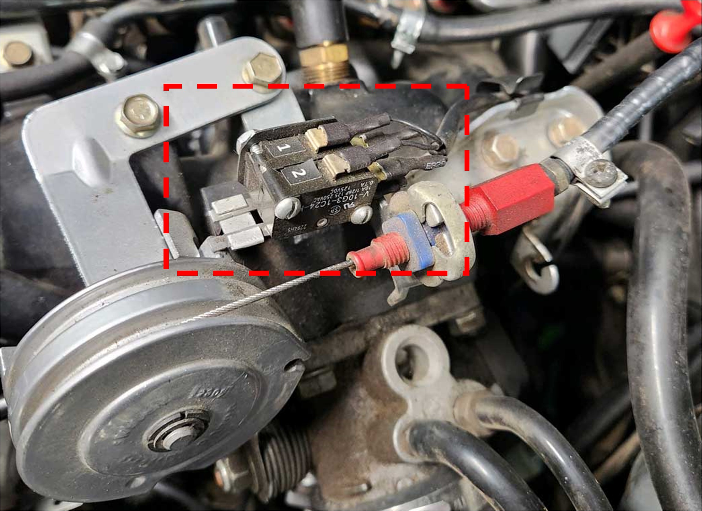 Additionally, I use micro-switches. These have been added to the throttle spool to override and shut the valves off whenever throttle is increased above idle. The micro-switches are wired to interrupt the ground circuit on the relays that control the valves. So this way the idle valves are only active at idle. |
||
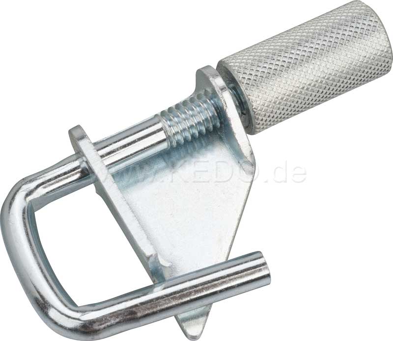 Crude but simpIe adjustment method to tune airflow through a soft hose. I'm using 1/2 inch I.D. silicone hose for the air lines from the intake tube (pre-throttle body) to the above valve and then to the intake manifold. Tuning the airflow in the hoses can be done simply with a hose line pinch clamp like this one. It squeezes the hose in very small, precise adjustments. |
||
https://www.youtube.com/watch?v=NrUIs_Jw3RQ |
||
So the above system created by Jon Lamb allows a user to manually
adjust the idle speed on the fly. This becomes useful
if whatever system you're using for idle control isn't perfect. Maybe you want a higher idle during
warm-ups or when the AC is on (combined with
warm-ups). For me, being able to do an easy quick adjustment
in my 242 Turbo was going to be a nice benefit.
|
||
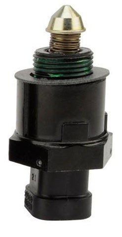
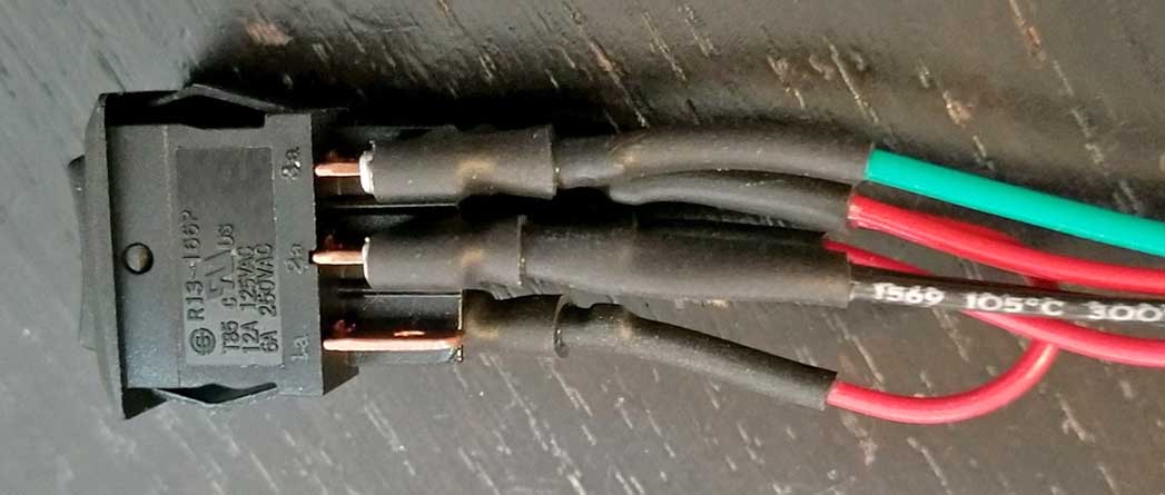
 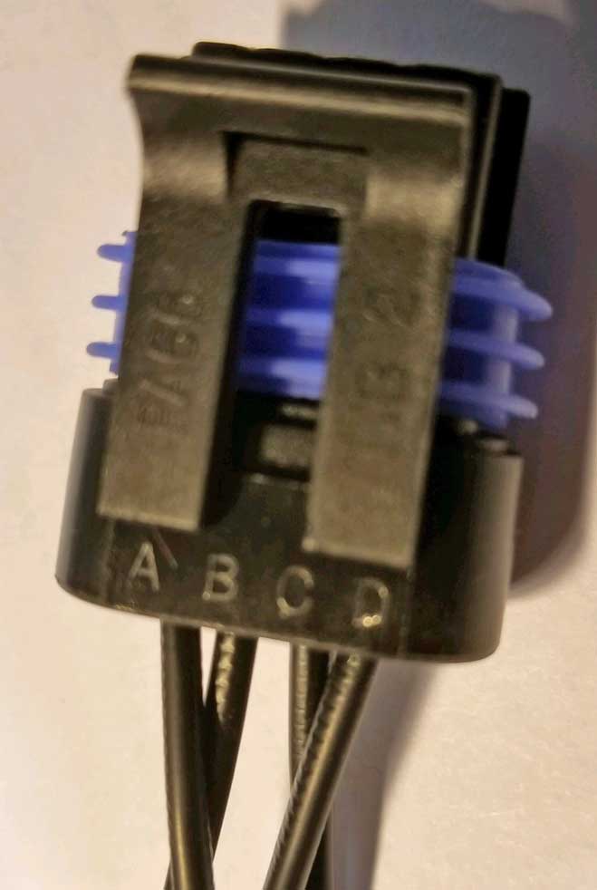 This is a GM stepper idle motor from approximately 2003 and later GM cars or trucks. This motor uses the 4-wire connector plug shown here. |
||
 <<<
This is an EARLIER style GM idle motor that came in cars
up until approximately 2003. It could also work, but you
would need to mount it differently than I did, since it's made with
threads to screw into a manifold, instead of the above
motor, which simply bolts on. And this earlier type uses a
different style 4-pole plug, so I won't be discussing how to use this motor.
<<<
This is an EARLIER style GM idle motor that came in cars
up until approximately 2003. It could also work, but you
would need to mount it differently than I did, since it's made with
threads to screw into a manifold, instead of the above
motor, which simply bolts on. And this earlier type uses a
different style 4-pole plug, so I won't be discussing how to use this motor. |
||
| As
you'll see, I've eliminated a few components
from the design shown in Jon Lamb's video. My
intent was to create a strictly stand-alone setup that
could manually adjust the idle up or down from the
dash. I'm
not re-inventing anything. My system will not switch between two different idle systems like Jon Lamb's did. I'm just
using and modifying the basic ideas offered by Jon in his
video. Circuits like this are a fairly new thing for me. So please don't mistake me for some kind of electronics wizard. I'm not, but I'm learning. |
||
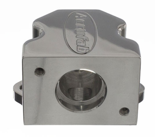
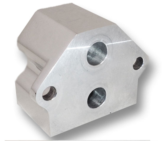
A Housing for the Idle Valve You may have noticed this GM idle motor is not really a complete valve. It's just a stepper motor with a plunger. I searched and could not find an all-in-one 4-wire idle valve with integrated IN and OUT hose barbs. Maybe one exists, but I found nothing that would work for me. So I started searching for an adapter housing that I could make, buy or modify to make that stepper motor into a full stand-alone idle air valve. There are a few custom housings I found like this BELOW. Most are very expensive. I chose this adapter from Accufab Racing. It was more money than I wanted to pay, but it works. It's designed to use the same GM idle motor I chose. This adapter was originally designed for adapting a GM stepper idle motor for use on a Ford engine.
|
||
Here's a view inside. 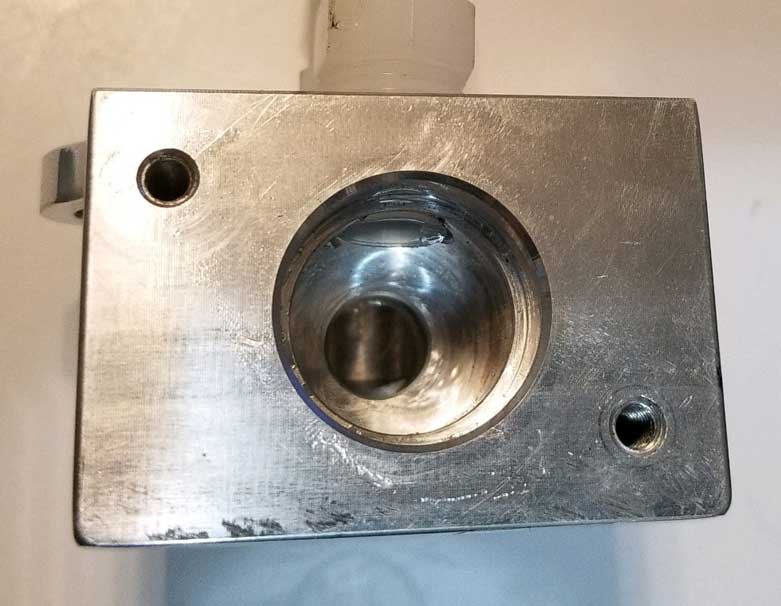 This hole starts at about .875 inch diameter. That first step is about .250 inch deep and it reduces to about .750 inch diameter. The .750 inch hole depth is about 1.1 inch and the final size beyond that is 7/16 inch (.4375 inch). If you're handy and have the machine tools or drills, making one of these would not be very difficult either out of aluminum or maybe even a sturdy, high-temp plastic block. |
||
|
Coincidentally, those IN and OUT holes on the bottom were 7/16 inch diameter, which is the correct size for a 1/4 inch NPT thread tap. 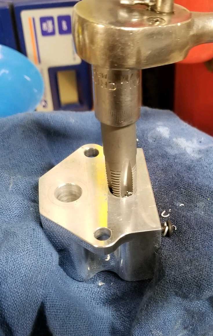 |
||
 After taping the threads, I inserted 1/4 inch NPT nylon hose barbs (for using 1/2 inch I.D. hose). These hose barbs have an I.D of .375 inch. Now I have a stand-alone idle valve (except for the circuits to run it). I was concerned that the .375 inch I.D. of those hose barbs might be too small for the airflow needed. If this became the case, then I could optionally drill the holes in the block to 37/64 inch for larger 3/8 NPT thread. That turned out not to be needed. |
||
Jon Lamb's video shows a hand drawn diagram showing all of the components he used to complete his project. He will also email you a PDF document showing more detail if you like. Check his video description for that. My version uses a few less parts, since I don't already have an existing GM ECU or an an EMS that uses this type of motor for primary idle control. So I don't need the relay or the toggle switch Jon used to switch from Auto to Manual Idle Control. I initially had a little trouble interpreting and following Jon's hand-drawn diagram, so I slowly figured out how all these components went together and then created a new, much cleaner, easier to read diagram below showing each component. This diagram below is a little different from Jon's diagram. It doesn't include the relay Jon used to switch between his factory EMS and manual idle control, since I'm not using that relay. Creating this diagram helped me to better visualize the task, since some of these components were new to me. It should help you understand better too. If you need any help with this diagram or with the diagram in Jon's video, feel free to contact me. |
||
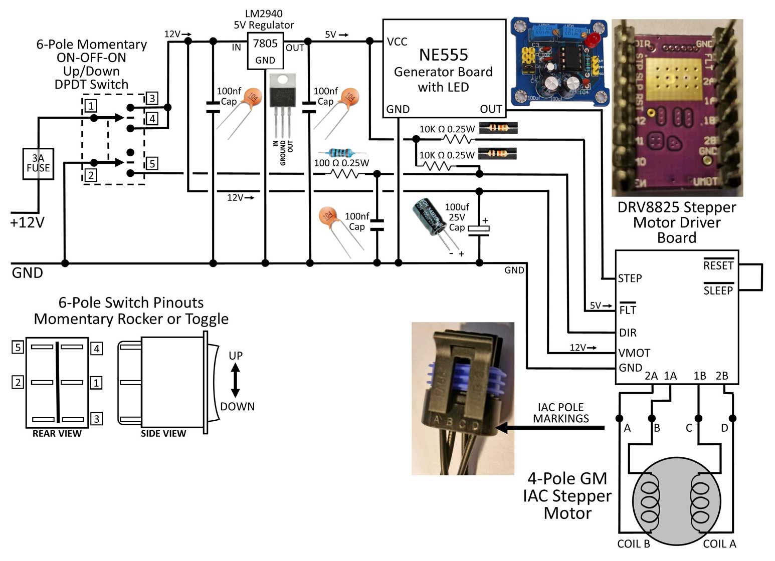 A printable PDF version of this diagram is available: CLICK HERE (1.2 mb) An inventory of PARTS is at the bottom of the page. |
||
| Before actually building the circuits, I hooked up the raw
circuits on a solderless breadboard (BELOW) to test it and make sure I had it
right. It worked as promised. If you check out the below video, you'll get to see my test in action. |
||
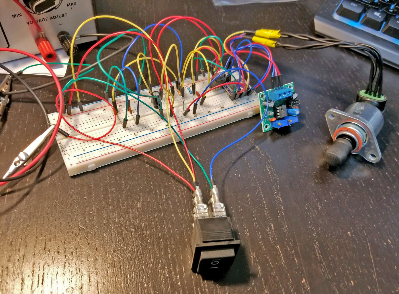 If this is all new stuff to you, more basic information on working with BREADBOARDS like this can be found here: https://www.youtube.com/watch?v=8hyL9DXYFZc&feature=youtu.be |
||
https://www.youtube.com/watch?v=HuoEHuL5Dzw&feature=youtu.be |
||
| FYI: 12V DC POWER SUPPLY If your work or hobby involves testing stuff like this, a 12 Volt DC Power Supply can be a big help. A similar power supply can be be found USED fairly inexpensively on eBay. This one is an old-school analog type. Most that are available now will have digital displays. 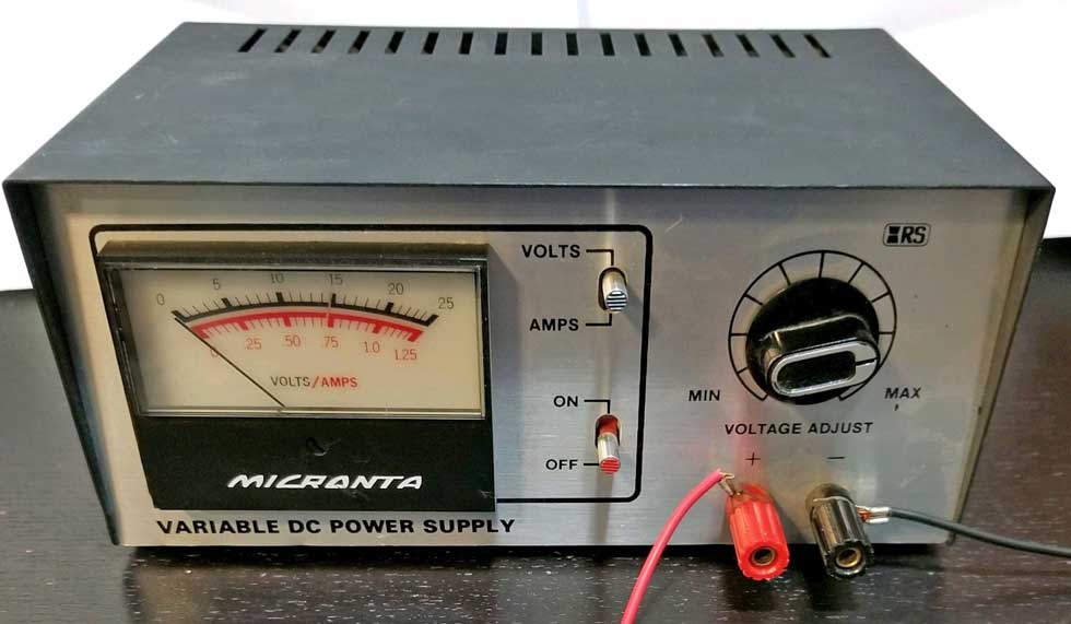 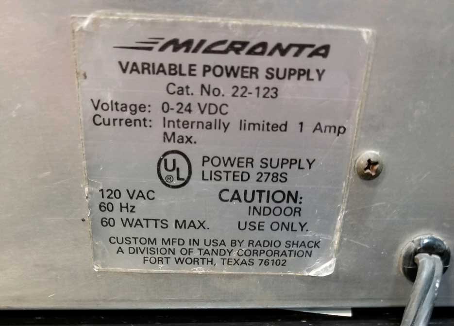 |
||
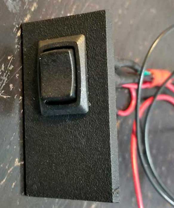 Here's the mini rocker switch. I added this to my dash for the idle increase/decrease adjustment. It's mounted in a dash switch blank panel in my 240. Photo of that below. |
||
 Here's a view of the left side. The mini rocker switch has .187 inch tabs on the back. I had some un-insulated female .187 inch terminals, so I covered them with heat shrink tubing. Pin-outs on this side view from top to bottom are: 12V OUTPUT (top), 12V INPUT (middle), and 12V OUTPUT (bottom). |
||
 Right side view. Pin-outs of this view from top to bottom are: Output to DIR (Direction) on DRV8825 Driver Board (top). GROUND (middle). Bottom tab is unused. |
||
I decided not to solder everything together like Jon did in his video. This is a personal preference thing. You might like soldering stuff. I don't particularly care for it. Solder joints are prone to cracking when used in a vibration environment, like a car. When that happens, you'll have a hard time finding the problem. 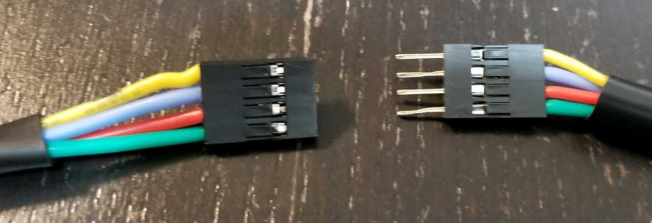 I bought a JST mini pin connector kit (see parts list below). It worked out nicely. This type of connector was used in the below project box to connect to the circuit board. The ABOVE connectors were used to connect the project box (which I put inside the dash) with four wires going through the firewall to the engine bay for the idle valve. The only problem with this type of connector is that it does not lock together, so taping it together might be a good idea. If I did this again, I would change to a Deutsch type connector CLICK HERE. |
||
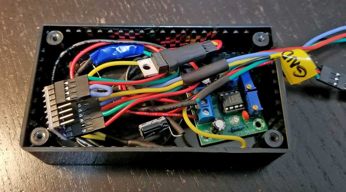 Here's the project box ABOVE that I stuffed everything into. When testing again at a final stage, things suddenly stopped working. I discovered that the 5V regulator was no longer working. Maybe I accidentally shorted it when moving stuff around. I replaced the regulator and it all worked perfectly again. Good thing I bought two of them. The next step was installing all this in the car. |
||
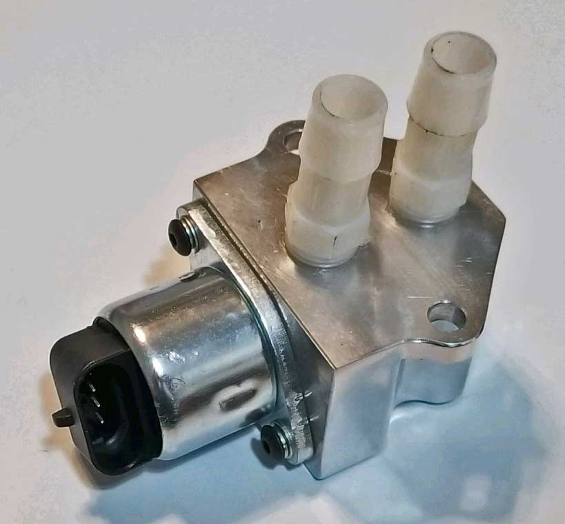
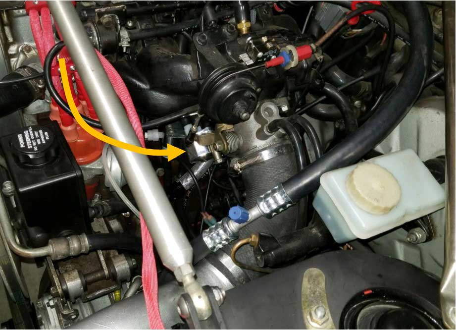 I mounted the new idle valve under the intake manifold here. |
||
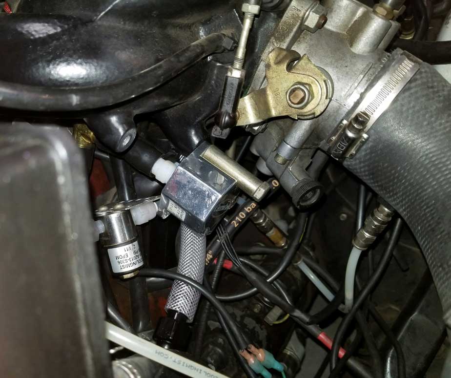 More close up view. |
||
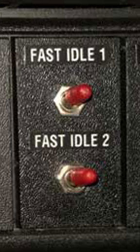
 Here's the idle adjustment rocker switch. It's set up to adjust the fast idle #1 circuit. Idle #2 is an extra circuit that can be used during warm-ups and it uses a separate idle valve. |
||
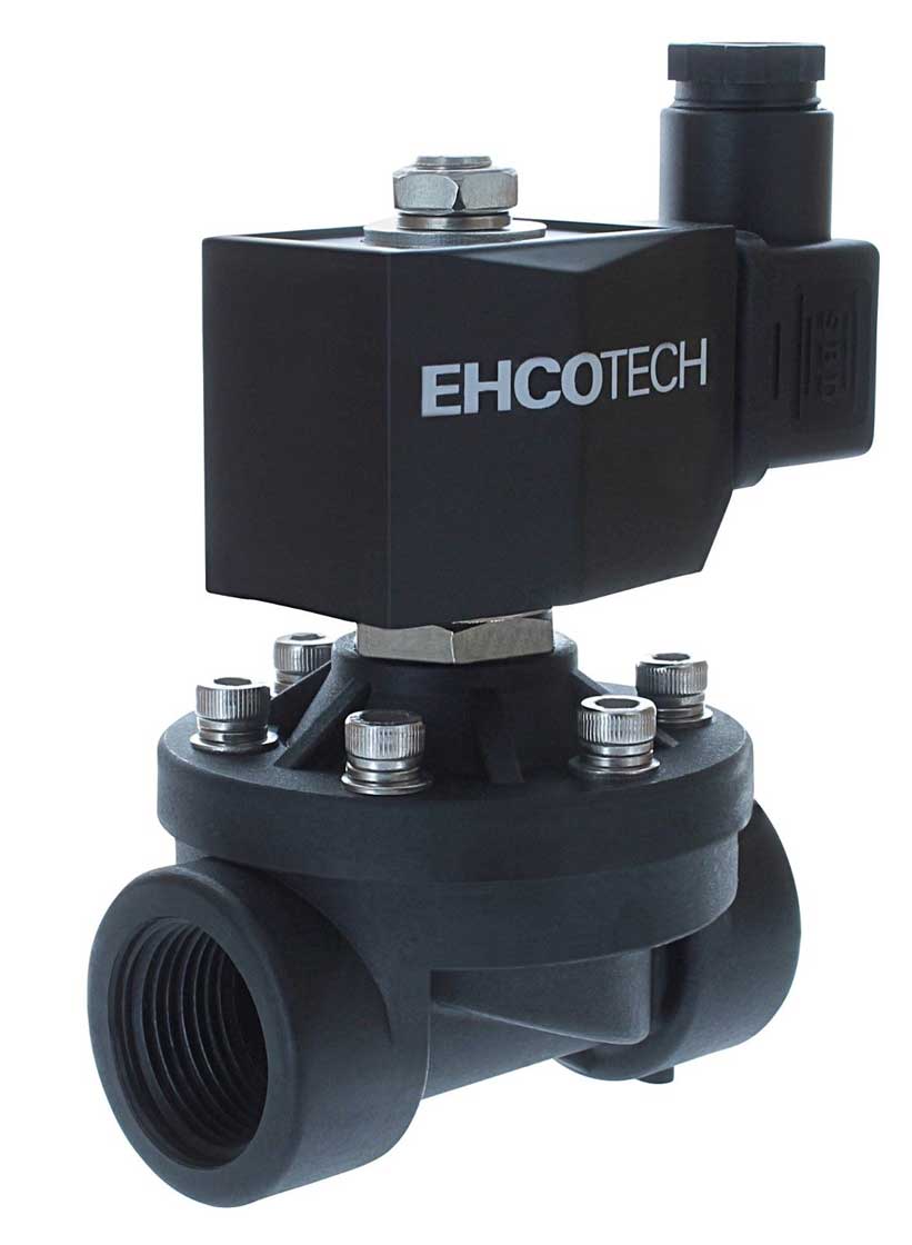 After trying this new idle setup using the two small Ehcotech valves shown at the top of this page, I found that the small Ehchotech air valve (with a 3/8 inch I.D.), which was used for idle #2 as an extra idle valve, was not allowing quite enough airflow during high airflow demand (mainly for cold idle). This was a unique problem that was mostly caused by a low compression engine (B21FT) with a big cam. Every engine is different. I decided that the small valve not big enough, so I bought this valve pictured above. It's a larger valve and also has a plastic body. The inner diameter is 3/4 inch. It solved the problem and now the engine gets plenty of airflow in any cold idle condition. I found this valve on eBay for about $25.
|
||
| If you have
any comments or questions, please feel free to
email. CONTACT |
| PARTS LIST |
|
IAC
motor for GM (2007 Chevy Silverado and many others).
4-pole connection. Cost will be $10 to $90, so shop
around. |
|
Connector plug with pigtail for above. Cost is
about $10.00. |
  |
DRV8825
Stepper Motor Driver Board or Module. Size is typically
less than an inch long. Typical input may be 5-45 volts.
Cost is about $2.00 to $4.00. |
 |
NE555
Pulse Module Square Wave Signal Generator Board with LED
Indicator. The LED is
needed for this project. There are a lot of these boards
without an LED. Get one with it. Size is
typically about an inch or so wide. Typical input will be
5-15 volts. There are three required connections:
VCC, GROUND and OUT. Cost is around $5.00 to
$15.00. |
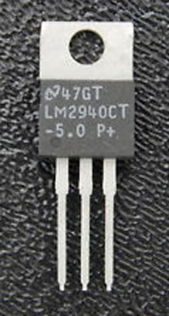 |
LM2940
5.0 volt regulator to reduce voltage to the Generator
Board. Cost is around $2.00. |
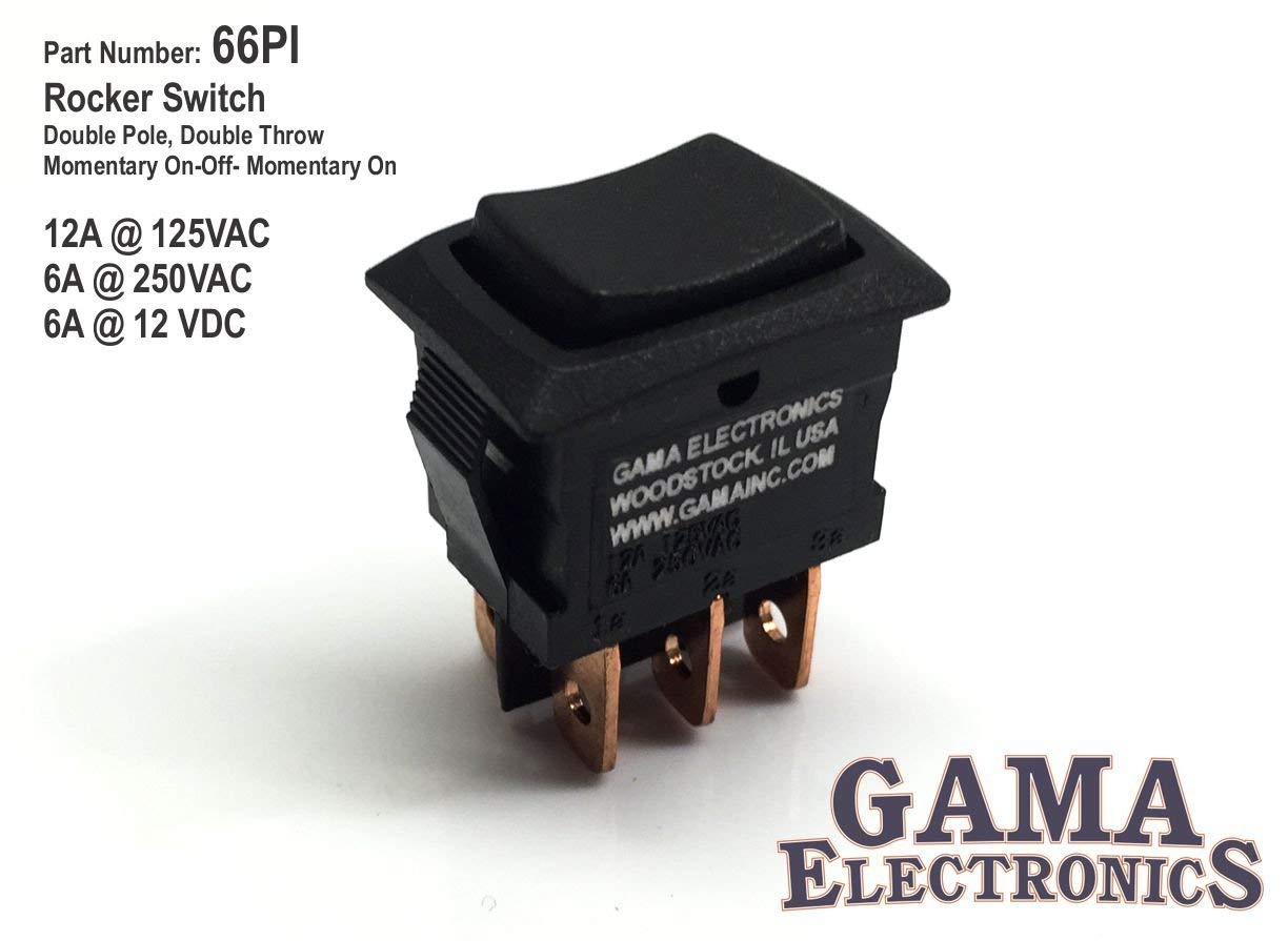 |
DPDT
(Double Pole, Double Throw) mini rocker switch, 6-poles on
the back. Momentary (ON), OFF, (ON) function. Front
size is about 1/2 x 1 inch. Cost is about $5.00. |
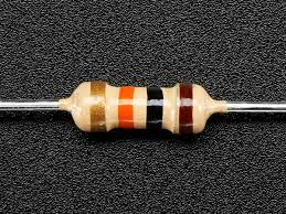 |
10k Ohm
Carbon Film Resistor. 0.25 Watt. TWO NEEDED. Cost
is small. |
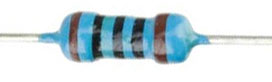 |
100 Ohm
Carbon Film Resistor. 0.25 Watt. Cost is
small. |
 |
100nf
(0.1uf) Ceramic Disc Capacitor. THREE NEEDED. Cost is small. |
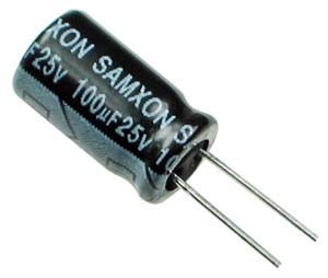 |
100uf 25 Volt Radial Electrolytic Capacitor. Cost is small. |
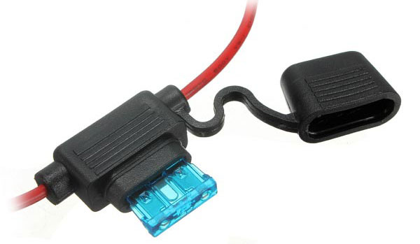 |
3 amp
fuse and fuse holder for 12V input to the rocker
switch. |
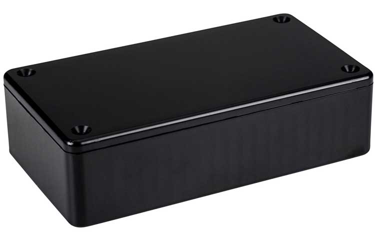 |
Hammond
1591BSBK ABS Project Box Black. 4.4 x 2.4 x 1.1 inches (112mm x 62mm
x 27mm). $5.00. |
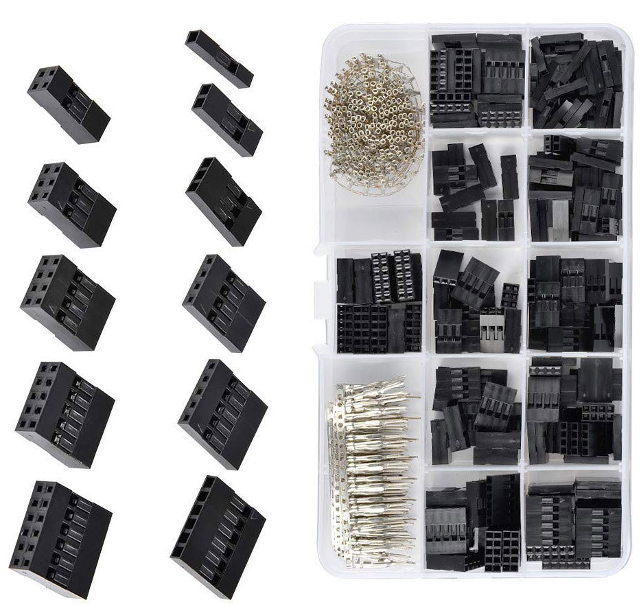 |
QLOUNI
2.54mm Pitch JST Pin Housing Connector Kit. About
$9.00. Not required. You can solder things also. |
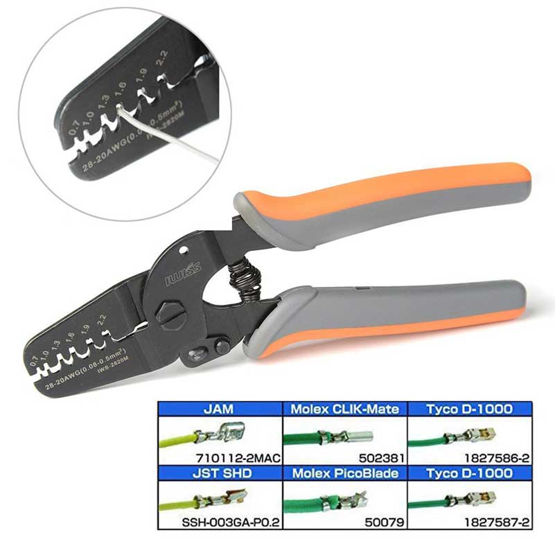 |
IWISS
Micro Open Barrel Crimping Tool for JST Terminals.
$17.00. Not required. You can solder things also. |
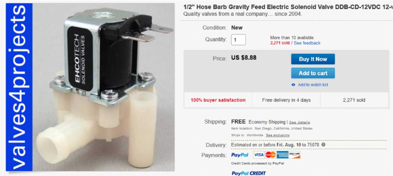 |
Ehcotech
12 volt electric valve, normally closed, 1/2 inch hose
barbs, 3/8 inch inner diameter. Under $10.00. |
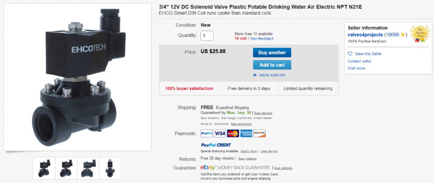 |
Ehcotech
12 volt electric valve, normally closed, 3/4 inch NPT
female, 3/4 inch inner diameter. About $25.00. |