| Crankcase Ventilation and Catch Can Installation |
 |
UPDATED: April 24, 2024
CONTACT

|
D O
M A I N S   |
|||
 |
 |
 |
 |
 |
 |
|
 |
 |
 |
 |

|

|
|
 |
 |
 |

|
|
 |
 |
 |

|
 |
 |
 |
 |
 |
 alternators are known for poor voltage.") |
 |
 |
 |
 |
 |
 |

|

|
 |
 |

|
 |
 |
 |
 |
 |
CONTACT
This page covers my installation of a catch can in my 242 Turbo and it discusses a lot of other stuff related to crankcase ventilation, commonly referred as Positive Crankcase Ventilation (PCV). Volvo information is pretty light on the use of a PCV VALVE and 4 cylinder engines apparently DID NOT use them. Volvo still refers to their most common 4 cylinder crankcase breather systems as PCV in their literature. So at least for the 4 cylinder engine it appears Volvo accomplished satisfactory crankcase ventilation with a design that did not need a traditional PCV valve. The U.S.D.O.T. also must have also been satisfied with the emissions these Volvos were producing, or I'm pretty sure we wouldn't have seen them imported to the U.S.
Here's what I could find for actual Volvo information on Crankcase Ventilation. This info is from TP30727 Emission Control Lambda 1977-85 240 260 and it covers B21-23, including B21FT.
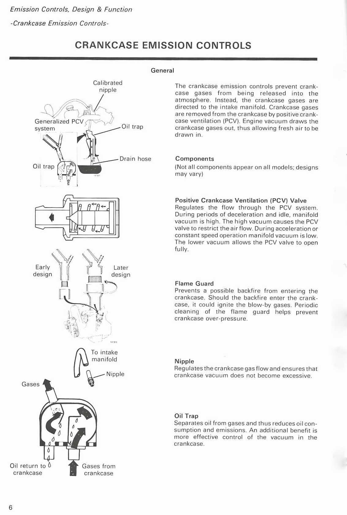
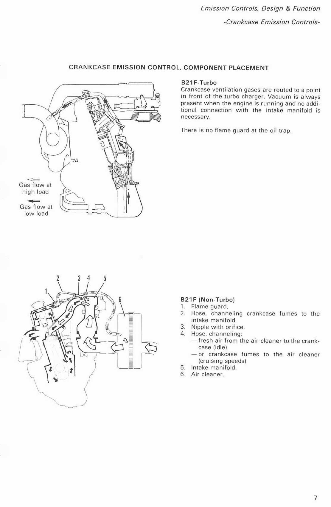
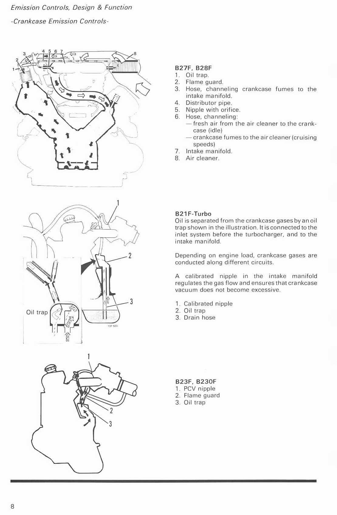
This info has a contradiction. It show two versions of a B21F-Turbo. One version has a vacuum hose (and calibrated nipple) from the flame trap nipple to an intake manifold vacuum port. Another version shows the vacuum nipple on the flame trap is CAPPED for a TURBO engine. This later CAPPED version is what I have ALWAYS seen on a Volvo TURBO engine over the years and it's what I believe is the correct version.
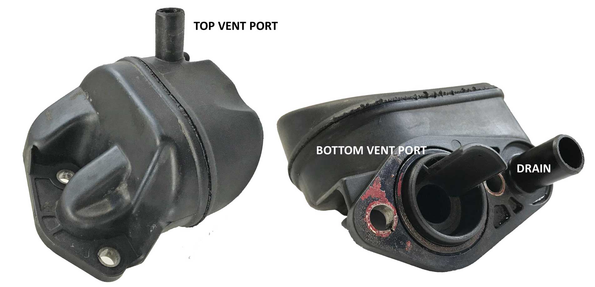
240 crankcase breather boxes are shown below. The early version is on the left and a later version is on the right. The center photo shows the flame trap, which is the small round filter device in the center photo. The flame trap is eliminated in Volvo TURBO engines.
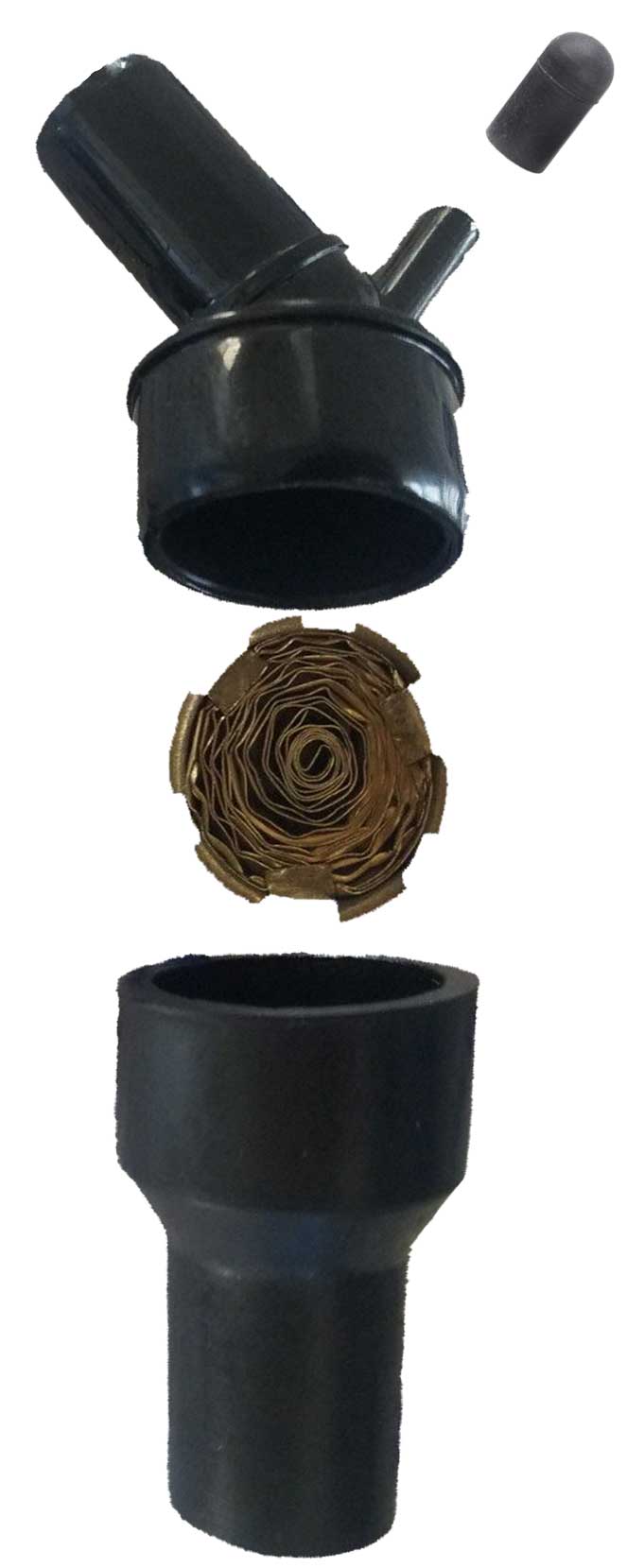
| Before
we get into catch cans, it's a good idea to know what Positive
Crankcase Ventilation (PCV) is and why it can be important. This video is a basic intro to PVC systems and how a PVC valve works. https://www.youtube.com/watch?v=pr5MZni4_Bc Or this video, which is a technician showing us and demonstrating how PCV compents work on a 4-cylider engine. https://www.youtube.com/watch?v=qwI4lNAziD0 A traditional spring-loaded PVC valve does THREE jobs: It will evacuate excess crankcase pressure when it occurs under any throttle position, plus it'll continuously ventilate the crankcase under mild vacuum, while protecting the crankcase from excess vacuum when the intake manifold is under very high vacuum (such as at idle). More discussion of PCV valves below HERE. If you want to learn some catch can BASICS, here's a good article to look at: https://www.enginelabs.com/news/video-the-importance-of-using-a-catch-can-system/ |
| Here are some videos that help explain Catch Cans and stuff. How to manage Crankcase vapors, PCV Valve and Catch Cans under boost. https://www.youtube.com/watch?v=sVhZJ2nb8-0 https://www.youtube.com/watch?v=2A4FijzXKyg |
| There
are a number of ways to install and plumb a catch can system. The below
diagram
is probably the most common way for a Volvo 4 cylinder, ASSUMING
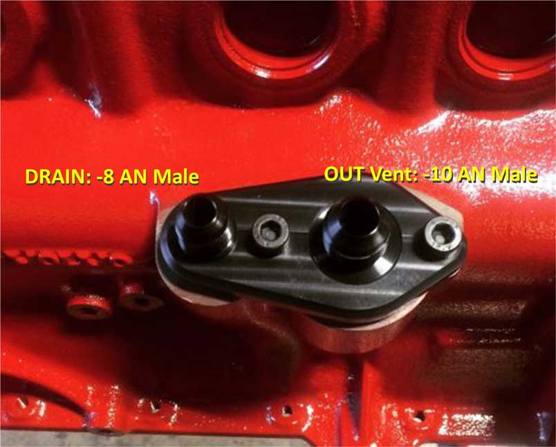
there's room on that side for the can. Sometimes there's not room. Certainly some features are optional in this diagram. Vent hose size is usually -10 AN or 5/8 inch ID. If an oil drain is used, it will usually be -8 AN or -10 AN (1/2 inch or 5/8 inch ID). 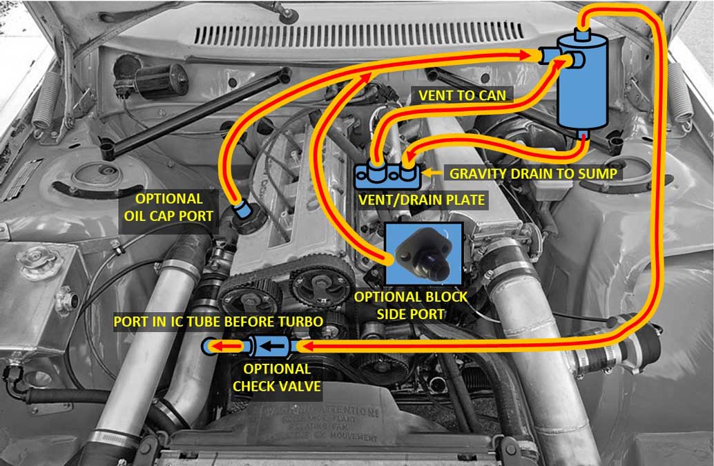 Volvo 4 cylinder Turbo engines always had a large vent hose from the oil trap box under the intake manifold to a port in the large air intake tube between the air filter and turbo. To my knowledge, Volvo has never explained why, but the accepted reason was that this helps re-circulate un-burned combustion gases back into the engine to be burned. Another function, which may be speculation, is there is a slight vacuum in that tube when the turbo is spinning fast. This vacuum, if present, should help to draw those un-burned gases out of the crankcase, which might help to create a very small vacuum in the crankcase. If you're unsure if that's a good thing, IT IS. Here's a rather annoying video which explains how to detect vacuum in a crankcase (except for most 4 cylinders). https://www.youtube.com/watch?v=l3ppNvofPHI If you had enough patience to watch until he got to talking about 4 cylinders, then I'll tell you MY B21FT flutters the paper exactly like this video when placed near the dip stick tube. CHECK VALVES: Many people have done these installations over the years without using check valves in vent lines, but it seemed to make sense to me to wall off boost or vacuum in any place where it benefits airflow or protects manifold vacuum, as long as the check valve flows freely enough to not adversely affect airflow when needed. I have included this type of optional check valves in this diagram. 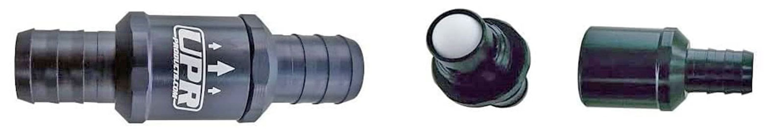 More info about these CHECK VALVES is further below. This image below represents how I eventually did my installation in my 1984 242 Turbo (although this is NOT MY ENGINE). I made this for educational purposes using another engine. I initially tried adding an optional line (like above) to the intake manifold with a check valve. That hose (above) raised my idle and stole some manifold vacuum, so I eliminated that line (why it's not shown here) and this image below is what I settled on. 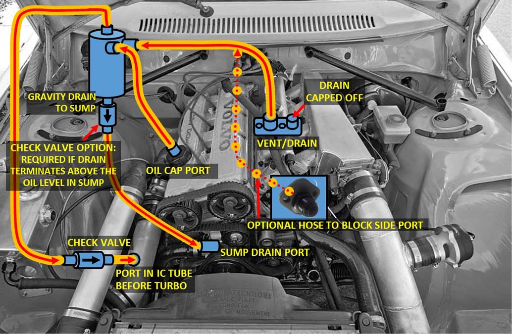 Check Valve in Catch Can DRAIN: More info about the oil drain check valve I used can be found further below. 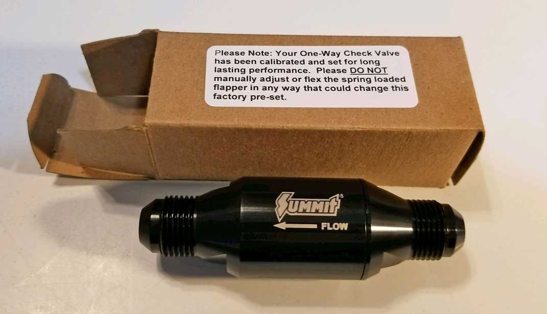 If you think maybe one can is not enough, you can also install DUAL catch cans for even better potential crankcase breathing. This is pretty common in high-performance turbos, but I have not tried dual catch cans. In this diagram below the can hose circuits are split, with one can sending vapors to the intake manifold port and the other sending vapors to the pre-turbo port. I believe a PCV valve is needed in the line from the crankcase to the catch can. Then I have added a check valve near the manifold to keep boost from entering the catch can. 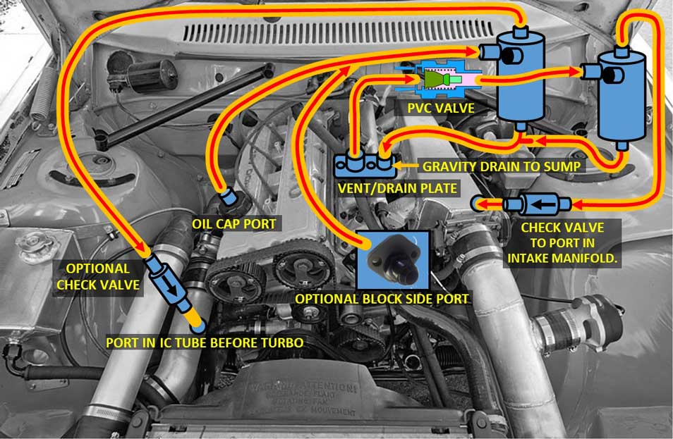 Using PCV valves have not been discussed until now. To my knowledge a PVC valve was never used by Volvo in a 4 cylinder. Can a PVC valve be of use now? Probably. A PCV valve is not a check valve. It will close (or mostly close) when it detects high vacuum from the intake manifold. This should help protect your manifold vacuum at IDLE, when you don't want uncontrolled vacuum coming into your manifold. I added an optional one-way check valve at the manifold to keep boost from entering the catch can. Here's another dual can version below, placing the PVC valve in the oil cap port. I have added a check valve near the intake manifold to keep boost from entering the catch can. It has not escaped me that there's really very little room on the intake manifold side for one catch can, let alone two cans. I've added another suggested diagram below for dual cans on the other side in a 240. 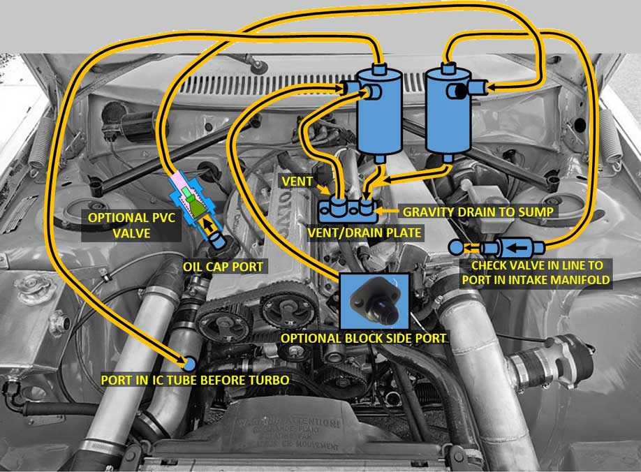 PCV VALVE?: What does this offer? The PCV valve is not a check valve. It will close (or mostly close) when it detects high vacuum from the intake manifold. This should help protect your manifold vacuum at IDLE, when you don't want uncontrolled vacuum coming into your manifold. I added an optional one-way check valve at the manifold to keep boost from entering the catch can. THIS ONE BELOW moves both catch cans to the passenger side where there's more room, as long as you don't have an AC accumulator there. If you don't have room there, you can likely find a place for two small cans more toward the front of the car. You have more choices when you eliminate a drain back to the crankcase. YES, these cans DO NOT HAVE DRAINS, so that makes this a much more simple plumbing arrangement. You can use two smaller catch cans which have dip sticks to check for oil. One can is plumbed to a PCV valve, then to an intake manifold vacuum port. I have added a check valve near the intake manifold to keep boost from entering the catch can. The other can has an air filter to vent to atmosphere, however it can be an option instead to delete the filter and run a hose to the intercooler tube before the turbo. 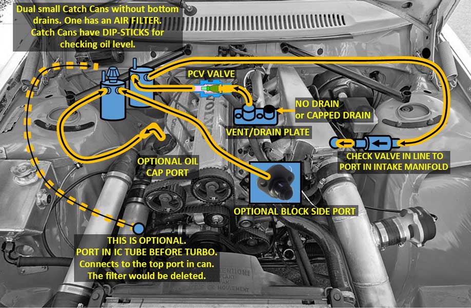 PCV Valves Most PVC valves are not made to be an IN-LINE type valves like the check valves shown in this page. Most are made to be pushed into a universal valve cover grommet with a 3/4 inch opening. Some valves are cheaply made (plastic) and they may be questionable for long life or use with a high-performance engine. All PCV valves are designed to be plumbed to an intake manifold port that has maximum vacuum at idle. 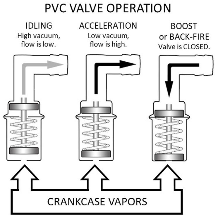 Almost all PCV valves will have a nipple for 3/8 inch ID hose on the end going to the intake manifold. If you find an inline valve, like this one below, it will usually have a 3/8 inch nipple on each end. 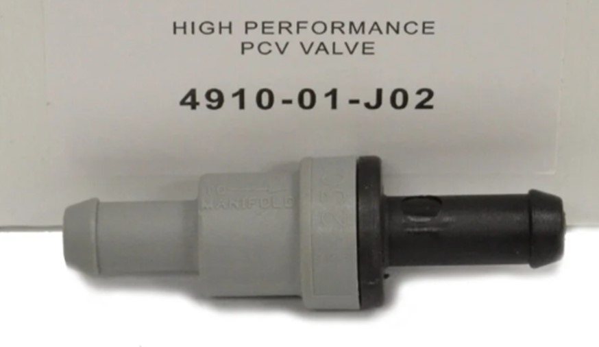 Jackson Racing offers an inexpensive IN-LINE PVC valve they claim is worthy of a turbo engine. If you think you need a higher flowing PCV valve, this one from hi-potek.com has a larger 1/2 inch vacuum hose nipple. 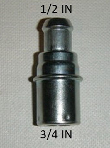 DF-17 Dual Flow PCV Valve by M/E Wagner. 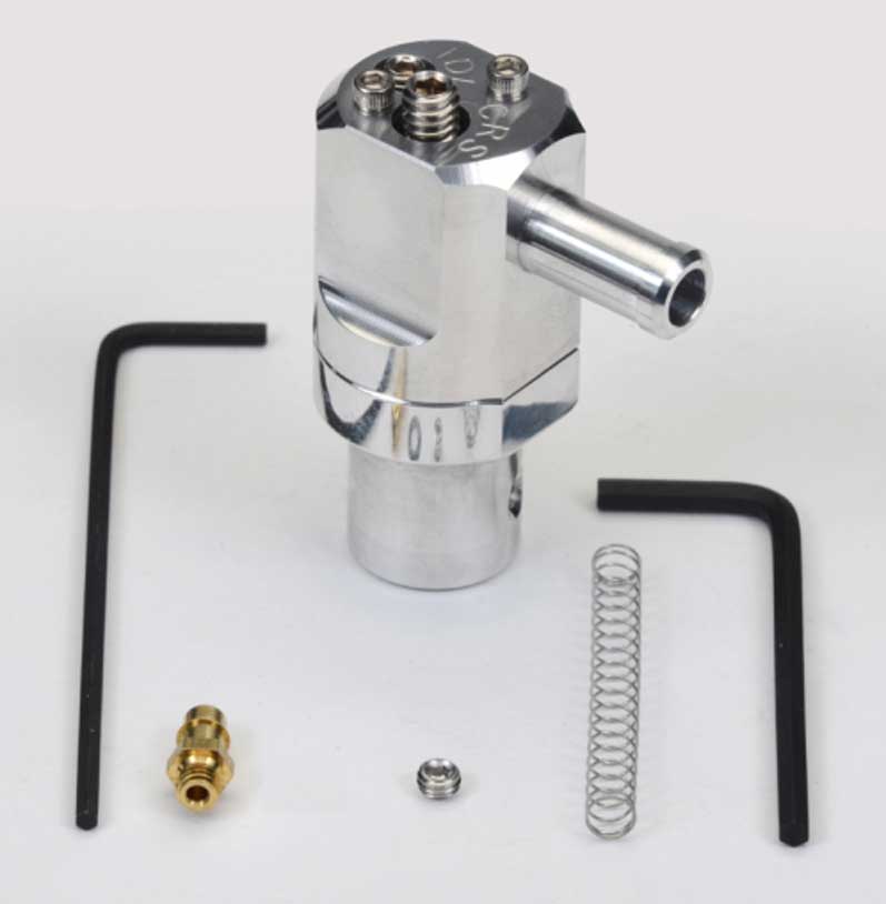 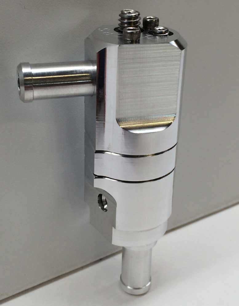 There is an interesting one ABOVE made by M/E Wagner Performance. It was designed for hot rod use and it's fully adjustable and may be disassemble and cleaned or rebuilt if needed. And it can be ordered as a push-in type (3/4 inch grommet) or as an inline valve (3/8 inch nipples). https://mewagner.com/. This DF-17 Dual Flow Mode Tuning Video will give you a quick understanding of how adjustable this valve is. https://www.youtube.com/watch?v=YClAva-MxF4 Yoshifab offers some of the items shown below in their pages at the following links: https://yoshifab.com/store/plumbing/catch-cans.html https://yoshifab.com/store/plumbing/crank-case-breathers/volvo.html The Yoshifab catch can is designed with THREE PORTS on top. This allows for TWO top IN ports and ONE top OUT port. Two IN ports allows you to vent crankcase vapor from two different sources. The illustrations ABOVE also show the optional use of a vented oil filler cap, an optional block side vent, and a vent/drain fitting for the block below the intake manifold, which are available from Yoshifab. Here are some images below of the Yoshifab catch can. The top and side ports are threaded -10 AN male thread. The bottom oil drain port is -8 AN male thread. 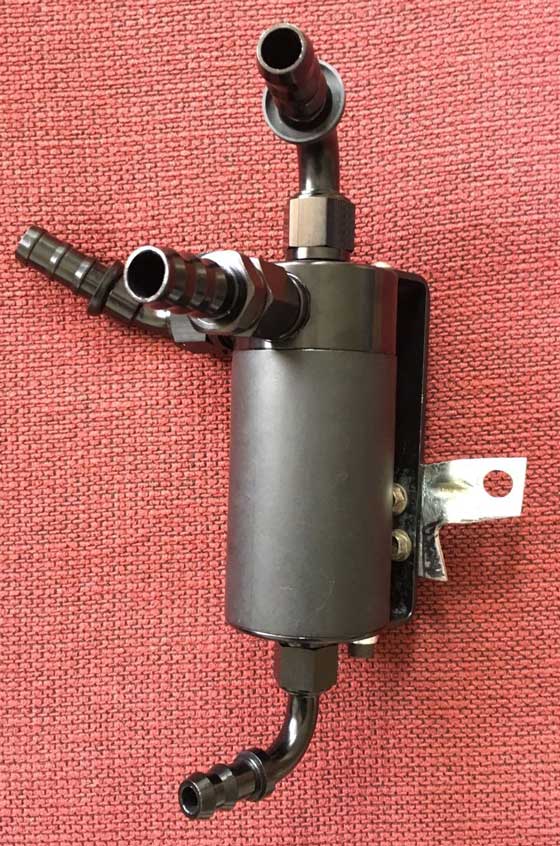 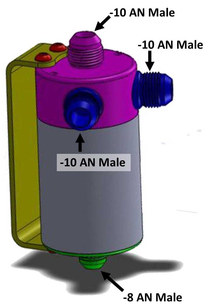
|
|
|
|
|
|
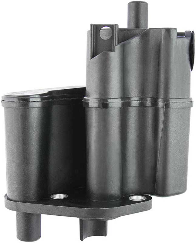
This block vent /
drain fitting plate from Yoshifab has been designed to
replace the original Volvo breather box under the intake
manifold. It has two ports. The small drain port on the left side has a -8 AN Male
fitting. The
larger vent port on the right side has a -10 AN Male fitting.
It's
needed if you plan to plumb a drain from a catch can to this drain
port. If you will not be draining oil here, this fitting is not
required. If you're using 5/8 inch ID hose, that size fits perfectly on the vent port on a factory Volvo oil trap box.
 In case you're not aware, the Volvo B21/23/230 engine block has a long
plastic tube inside that extends from that drain port above down
into the oil sump. The bottom of that tube is
submerged below the oil level. When this drain is extended below the
oil level, it ensures that this pipe drains freely and does
not get any interference from positive crankcase pressures.
So basically this Yoshifab plate is designed so that when an
external catch can is installed, the bottom of the can SHOULD be placed somewhere reasonably close to and ABOVE the level of
this drain port. This is not always convenient in a
Volvo due to tight space, although there seems to be plenty of people who
have managed to accomplish this. I did not as you'll see a bit further below.
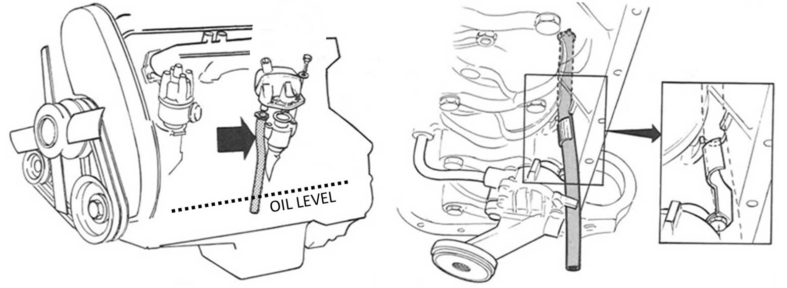
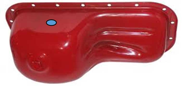
As seen above, the oil drain below the stock crankcase vent box for a B21/23 or B230 extends down past the oil pump and ends just above the bottom of the oil pan. It's designed to end BELOW THE OIL LEVEL, so it doesn't get affected by elevated crankcase pressures due to boost. As you'll see in MY installation below, I opted to NOT use the drain port on this block vent fitting.
That drain port can be capped off with a -8 AN Female Cap,
such as this item from Summit Racing: Earl's -8 AN Cap
(AT992908ERL). This is what I used, since the drain I used was on the
other side of the engine.
|
|
|
|
|
|
|
|
Here's my 240.
Things are harder to see in this photo. I decided to mount the catch can on the right (EXHAUST) side of the engine bay, in the back corner. My drain from the can down to the crankcase is on the exhaust side. I'll explain more below. 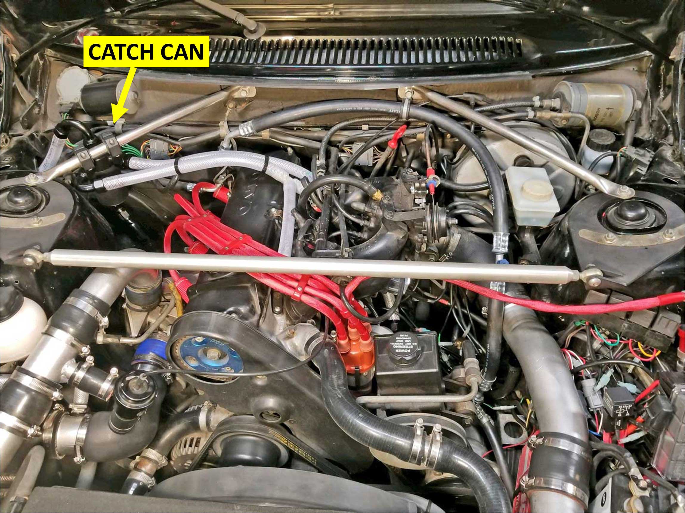 A HOT Catch Can: One thing about putting the catch can on the EXHAUST side . . . It gets hot. Is this bad? No, I don't think so. I actually think a HOT catch can is much better. Some high end catch cans are available with heating devices, such as ports that run hot coolant through them. A hot catch can will have the potential benefit of turning any moisture into vapor faster, which will hopefully then slowly exit out with other vapors and not stay in the can or return to your sump. The hotter the better in my opinion. |
|
|
|
|
| MOUNTING THE CATCH CAN IN MY 240 The brackets I used are aluminum mounting brackets for ATV lights. I found them on Amazon: https://www.amazon.com/gp/product/B072M59GXX/. These brackets are made for a 3/4 inch wide tube (also available for other sizes). 3/4 inch is the size of the 242 GT diagonal brace I have in there. 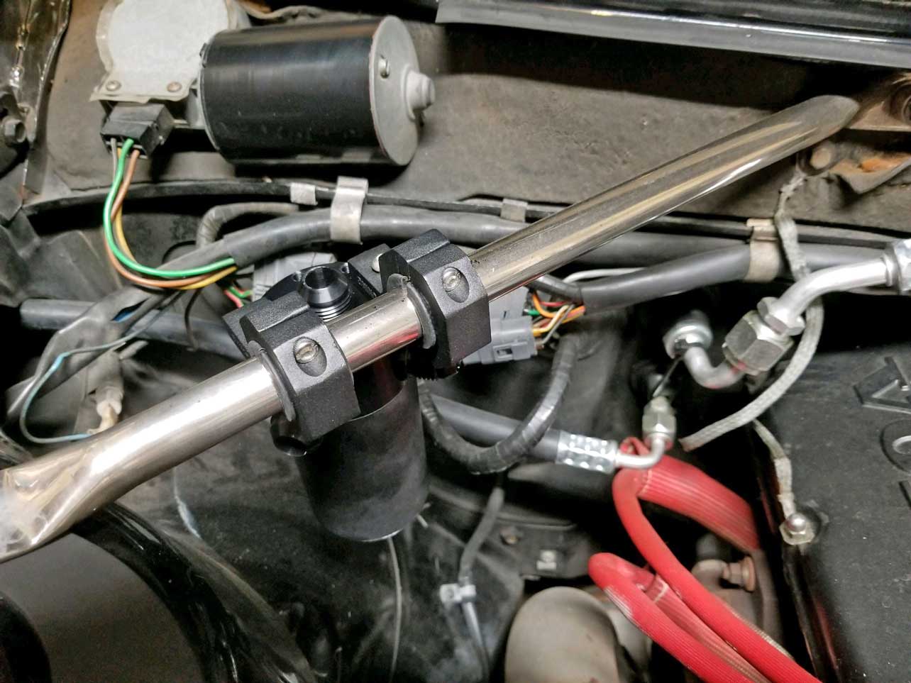 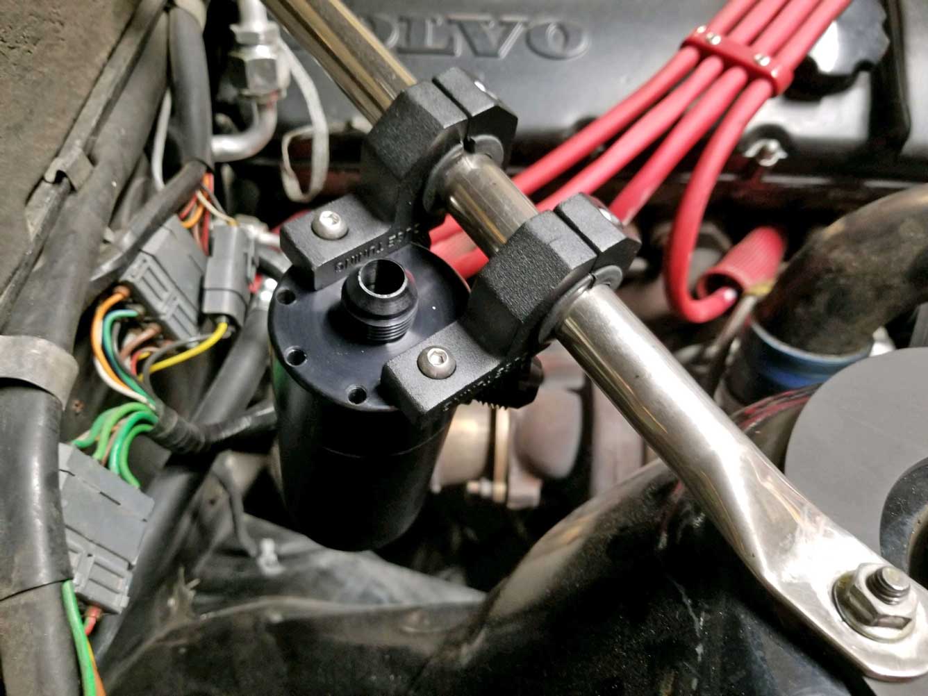 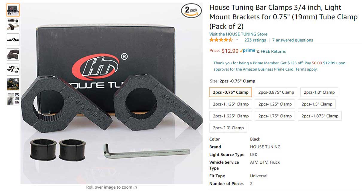 |
|
|
|
|
|
DRAIN ROUTING TO THE SUMP
My plan routed the catch can drain down into a Y-fitting that joins with the turbo oil drain just above the block drain. This Y-fitting tends to make things a little complicated down there as you can see here, so some planning was needed for all these AN hose fittings to fit in a small space. The turbo oil drain that I previously installed uses Summit PTFE lined racing hose, which is a high temperature hose designed for hot oil (rated to 400 degrees Fahrenheit). So I used the same type PTFE hose for the catch can drain. I wanted to use a hose that was rated for high temperature since this stuff is so close to the exhaust manifold and turbo. 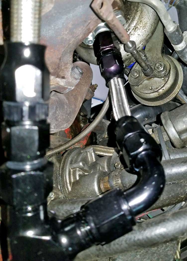 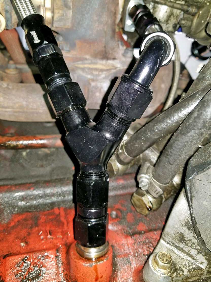 I would prefer to NOT use this Y-fitting. I would rather have a dedicated drain port down low on the side of the oil pan (below the oil level), but this is something I think I'll work on later, since I didn't feel like removing my oil pan at this time to drill a hole. More info on THIS: CLICK HERE |
|
|
|
|
|
Here are the connectors used to assemble this
Y-fitting. The Y-fitting has -10 AN male ends. It
uses a reducer to -8 AN for the hose that goes up to the
breather box.
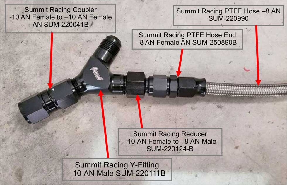 Not shown here is the turbo oil drain (seen in above photos), which connects to the other upper end of the Y-fitting. That hose uses a short piece of Summit Racing -10 AN PTFE hose (SUM-2201010), one Summit Racing PTFE Hose End -10 AN 90 degrees (SUM-250087B), and one Summit Racing PTFE Hose End -10 Straight (SUM 250090B). Specific detailed information about the turbo drain hose fitting that fits into the block can be found in a separate article HERE. Assembling PTFE hose ends is not difficult, but you'll need some guidance if it's your first time. There are good instructions here: https://anfittingguide.com/install-ptfe-hose-fittings/. And a good video below.
|
|
|
Here's a good video on assembling these PTFE fittings: https://www.youtube.com/watch?v=978BYt_MUK0 |
|
|
|
|
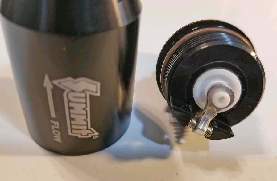
| AIRFLOW CHECK VALVES I installed two one-way check valves in the airflow hoses during my installation.  The above check valve has an ARROW which shows the a airflow direction. The ball inside will prevent flow in the opposite direction. There are a lot of check valves out there. I wanted one that I thought would not restrict flow and I wanted it to fit the 5/8 inch ID hose I was using. I chose this one above made by UPR. It's pricey, close to $50 each. It uses a PTFE ball and light spring inside. It will easily disassemble if you want to see what's inside. When I blew through the valve it seemed to have very little restriction and the ball provides a 100% seal against reverse flow. https://www.uprproducts.com/upr-plug-n-play-billet-check-valve 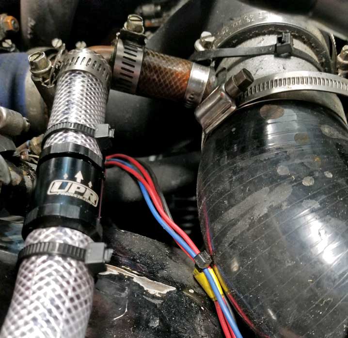 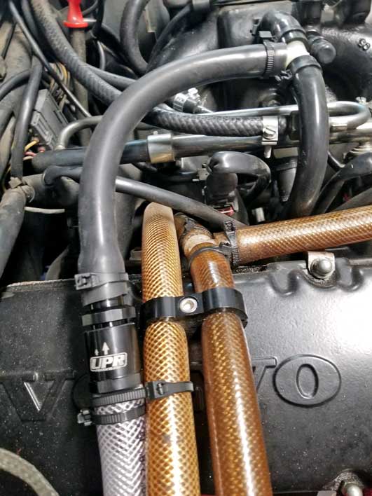 The valve in the left pic is near the port going into the pre-turbo inlet hose. The valve on the right is there to allow intake manifold vacuum to reach the catch can, but it won't allow boost. I tried this setup, but found it raised my idle. I didn't want that, so I eliminated this line. |
|
|
|
|
|
OIL DRAIN CHECK VALVE
I installed a one-way check valve in the oil drain hose between the catch can and the Y-fitting. It needs to be placed so flow goes down only. A check valve is used in this situation because the drain goes into the oil sump above the oil level. A different option would be if the drain went into the sump below the oil level. A check valve WOULD NOT be needed if this tube drained to a port BELOW the oil level. 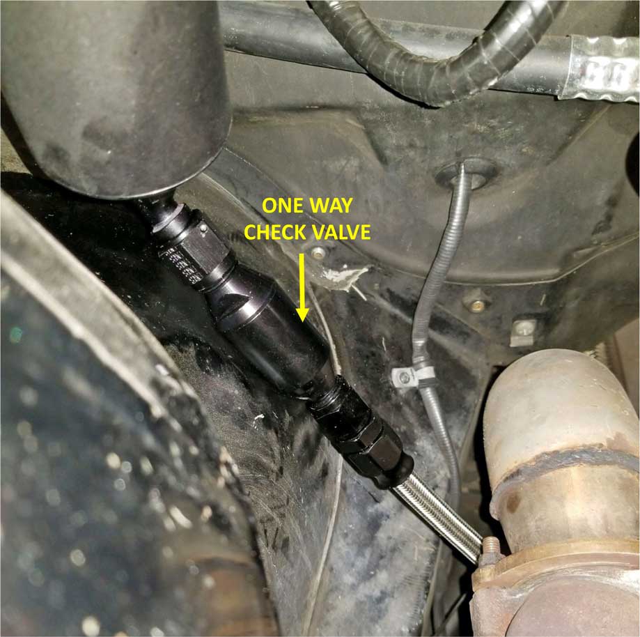
You can't see it in this photo here, but I used a 45 degree adapter (-8 AN Female to -8 AN Female) between the catch can and the check valve. Like this one: https://www.jegs.com/i/Earls/361/AT939208/10002/-1 More detail about the drain check valve is below. |
|
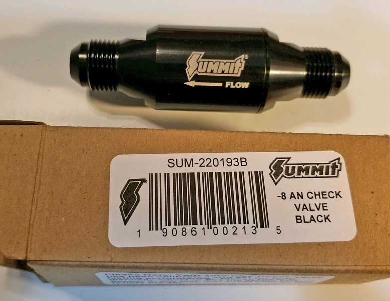  This is the check valve.
It accepts -8 AN fittings on both ends and can be found
at Summit Racing here: One-Way Check Valve -8 AN
Male (SUM-220193B).
The summit instructions will tell you not to screw with the spring that holds the check-valve closed. I couldn't stop myself. I felt it was too tight, so I tweaked it until it was much easier to push open. I want this to drain freely and not back up into the catch can. I'm pretty confident in my decision. |
|
|
|
|
|
|
|
Ventilation
through the side Block Fuel Pump Opening
|
|
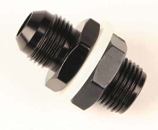
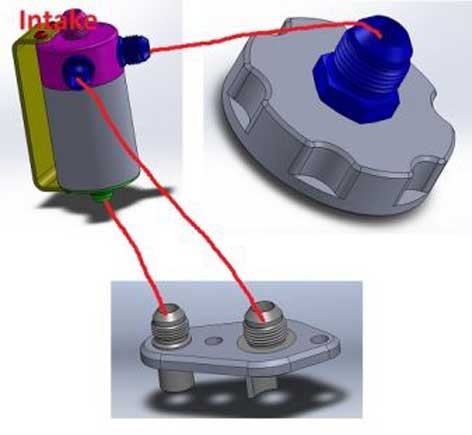
Yoshifab offers this adapter plate if you would like to
mount an AN fitting vent to the old fuel pump opening in the
side of the engine block. I'm using this opening as one of several crankcase vent locations. I'm not using
an oil filler cap with a vent fitting, but that
option is available. This plate has a removable AN
fitting in case you want a different sized fitting on
there. The plate is threaded -10 AN Straight Thread
Female (O-Ring). An o-ring is used to
seal this connection to the plate. 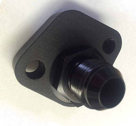 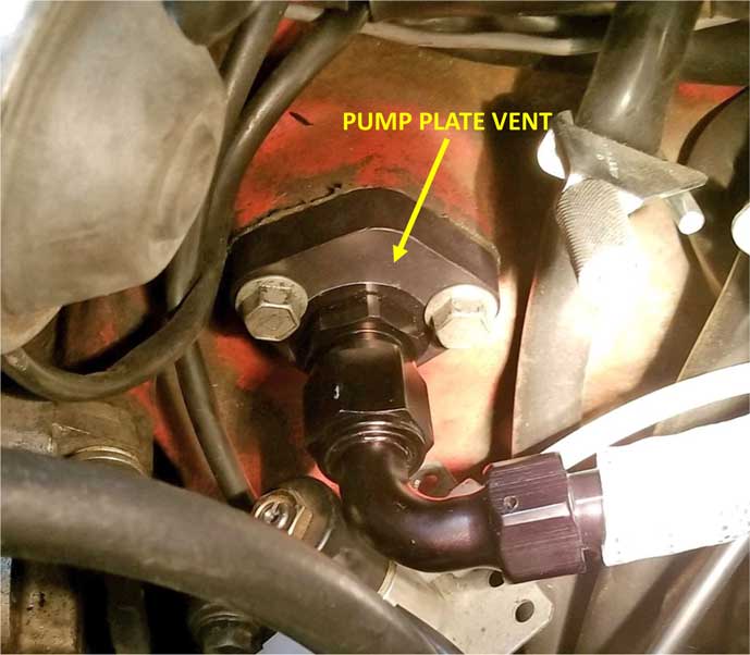 The 90 degree fitting I'm using is this one: -10 AN Summit Racing Twist-Tite Swivel Hose End 90 (SUM-260087B). The barbed end is made for -10 AN Summit Twist-Tite rubber hose, which has a 5/8 inch ID. You can also use Aeroquip Socketless fittings in size -10 AN. Summit Twist-Tite hose is a similar hose (but cheaper) compared to Aeroquip Socketless hose, however the Aeroquip products, particularly the fittings, are considered to be better quality. For a light-duty application like a catch can, I didn't consider the higher quality to be critical. 
|
|
|
|
|
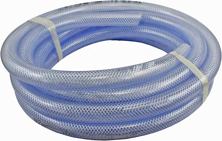 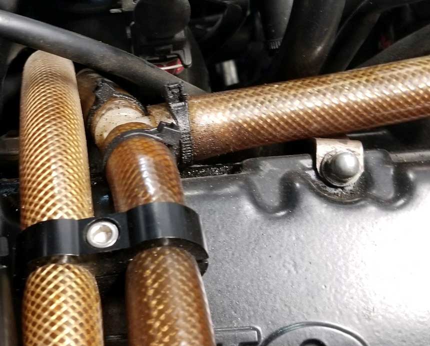 Yoshifab suggested using 5/8 inch PVC clear reinforced flexible tubing as a less expensive option over Aeroquip Socketless or other high cost racing hose. The clear tubing has a fair temperature rating (150º F) and since it's semi-transparent, you can see almost what's going on inside. I bought some on Amazon: https://www.amazon.com/gp/product/B01MRUROKO/ Of course the second photo above shows how this hose will eventually become discolored after a few years of engine heat. It also shrinks slightly and hardens a bit. The shrinkage is a small concern, since it means this hose was a tight fit on the nipples in the beginning, but can later be more loose or could slip off the nipples if clamps aren't used. Clamps will keep them tight. Zip-ties too, but they will not be as tight as clamps. So keep this in mind for your hose decisions. 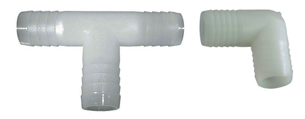 Nylon barbed tee or 90 degree fittings are an easy and suitable solution for joining this hose. |
|
|
|
|
|
Here's a pic showing the 5/8 inch clear PVC tubing in
use at the catch can.
That top port got routed through the back of the right strut tower, then to the front of the engine bay. It's connected to the intake air tube between my air filter and turbo. That is a 150 degree curved fitting I used on top of the catch can. This one: -10 AN Summit Racing Twist-Tite Swivel Hose End 150 Degree (SUM-260091B). 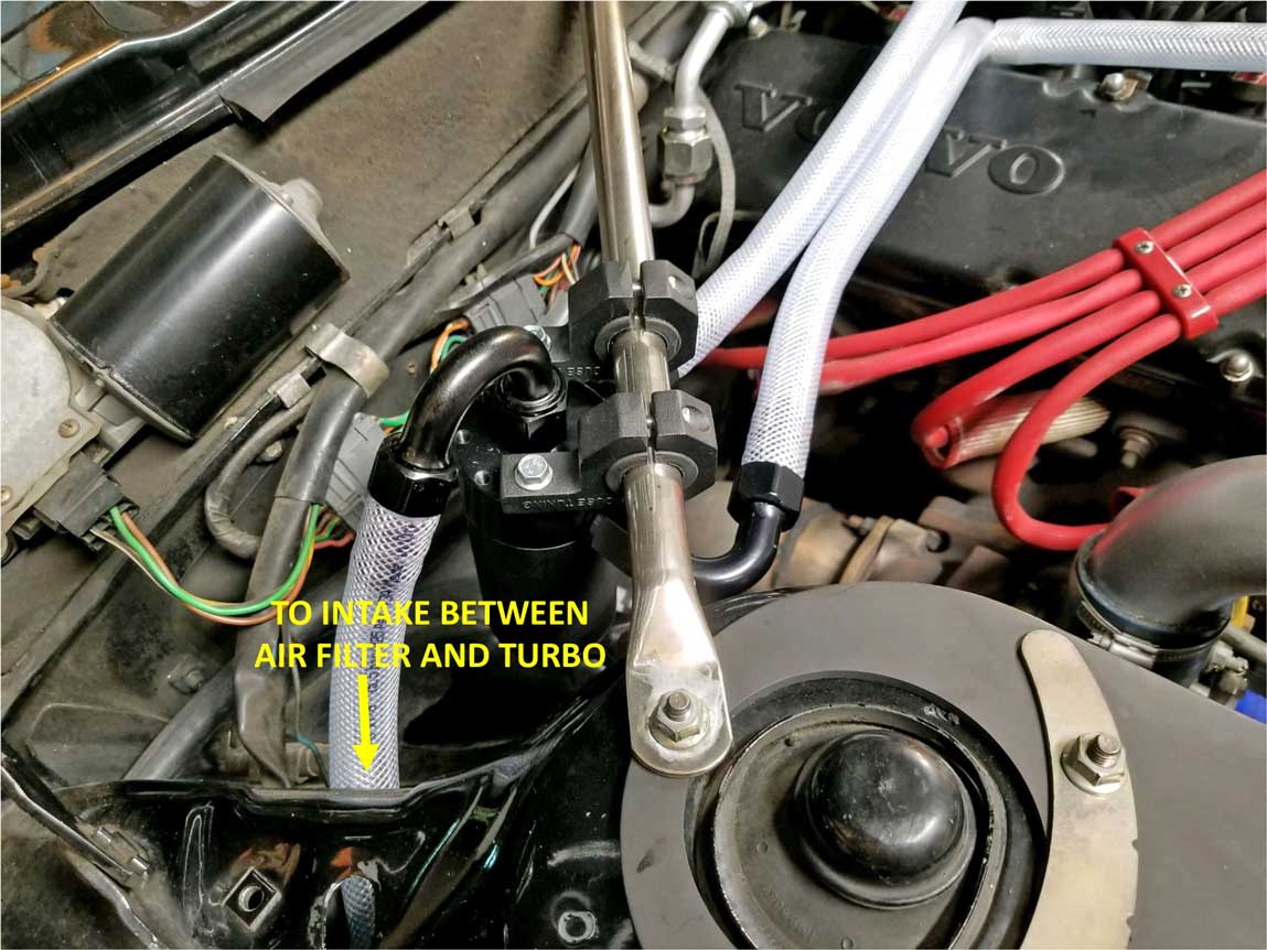 |
|
|
|
|
Here's a pic of that hose going to my intake tube after
the filter and before the turbo.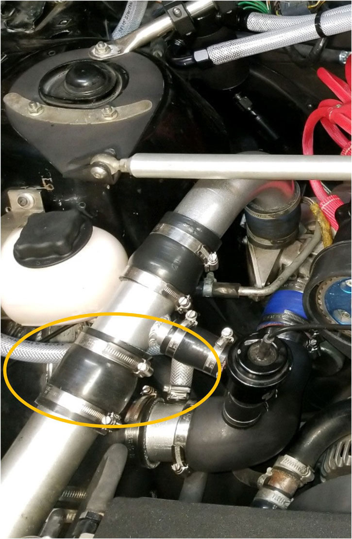 |
|
|
|
|
The straight fitting closest to the firewall on the
catch can is for the hose going across the cam cover and
then down past the intake manifold to the block breather
vent. This fitting is -10 AN Summit Racing
Twist-Tite Swivel Hose End (SUM-260090B).
The same fitting can be used on the Yoshifab vent plate
that replaces the stock breather box.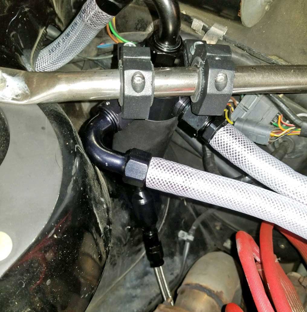 The curved fitting next to the shock tower is a 120 degree curved fitting. That hose goes to a nylon T-fitting near the intake manifold (it can be seen in next pic). This 120 degree fitting is -10 AN Summit Racing Twist-Tite Swivel Hose End (SUM-260088B). |
|
|
|
|
| Here you can see the hose closest to the
front of the car continues down through the intake
manifold and then turns forward to the fuel pump plate
vent. The tee-fitting you can see here sends another
hose forward to the cam
cover vent. I have a 90 degree
elbow-fitting shoved in the cam cover vent hole.
That elbow was slightly loose it that hole, so I added a
small piece of heat-shrink tubing to the end and it then
fit in the hole nice and snug. These 5/8 inch OD nylon T-fittings and Elbow-fittings are cheap and nylon will hold up to high temp conditions. 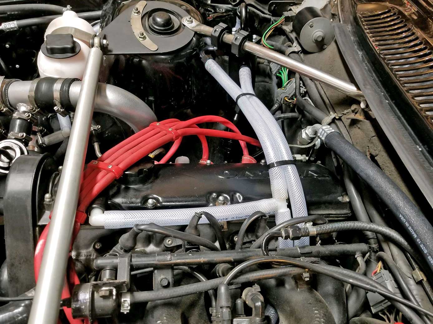
|
CONTACT